-
Cisco MWR 2941 Mobile Wireless Edge Router Software Configuration Guide, Release 15.0(1)MR
-
About This Guide
-
Cisco MWR 2941 Router Overview
-
Cisco IOS Software Basics
-
First-Time Configuration
-
Configuring Gigabit Ethernet Interfaces
-
Configuring Layer 2 Interfaces
-
Configuring HWIC-9ESW Interfaces
-
Configuring VLANs
-
Configuring IEEE 802.1Q Tunneling, VLAN Mapping, 802.1ad, and Layer 2 Protocol Tunneling
-
Configuring STP
-
Configuring MSTP
-
Configuring Optional Spanning-Tree Features
-
Managing the MAC Address Table
-
Configuring Cisco Express Forwarding
-
Configuring Resilient Ethernet Protocol
-
Configuring Ethernet Link Operations, Administration, and Maintenance
-
Configuring Clocking and Timing
-
Configuring Synchronous Ethernet ESMC and SSM
-
Configuring MLPPP Backhaul
-
Configuring Multiprotocol Label Switching
-
Configuring Routing Protocols
-
Configuring Bidirectional Forwarding Detection
-
Configuring Pseudowire
-
Configuring Layer 3 Virtual Private Networks
-
Configuring Quality of Service
-
Configuring Link Noise Monitor
-
Configuring Cisco Discovery Protocol
-
Monitoring and Managing the Cisco MWR 2941 Router
-
Index
-
 Feedback
Table Of Contents
Structure-Agnostic TDM over Packet
Structure-Aware TDM Circuit Emulation Service over Packet-Switched Network
Transportation of Service Using ATM over MPLS
Transportation of Service Using Ethernet over MPLS
Configuring Structure-Agnostic TDM over Packet (SAToP)
Configuring Circuit Emulation Service over Packet-Switched Network (CESoPSN)
Configuring a CESoPSN Pseudowire with UDP Encapsulation
Configuring Transportation of Service Using ATM over MPLS
Configuring the ATM over MPLS Pseudowire Interface
Configuring Transportation of Service Using Ethernet over MPLS
Configuration Examples for Pseudowire
CESoPSN with UDP Configuration
Ethernet over MPLS Configuration
Configuring Pseudowire
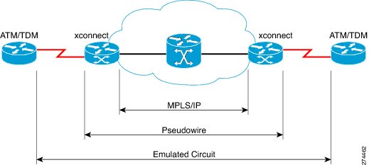
Cisco Pseudowire Emulation Edge-to-Edge (PWE3) allows you to transport traffic using traditional services such as E1/T1 over a packet-based backhaul technology such as MPLS or IP. A pseudowire (PW) consists of a connection between two provider edge (PE) devices that connects two attachment circuits (ACs), such as ATM VPIs/VCIs or E1/T1 links.
The following sections describe how to configure pseudowire on the Cisco MWR 2941:
•
Configuration Examples for Pseudowire
Figure 22-1 Cisco MWR 2941 Router in a PWE3—Example
Understanding Pseudowire
PWs manage encapsulation, timing, order, and other operations in order to make it transparent to users; the PW tunnel appears as an unshared link or circuit of the emulated service.
There are limitations that impede some applications from utilizing a PW connection. For more information, see the section describing the PW service.
Cisco supports the following standards-based PWE types:
•
•
•
•
Structure-Agnostic TDM over Packet
SAToP encapsulates TDM bit-streams (T1, E1, T3, E3) as PWs over PSNs. It disregards any structure that may be imposed on streams, in particular the structure imposed by the standard TDM framing.
The protocol used for emulation of these services does not depend on the method in which attachment circuits are delivered to the PEs. For example, a T1 attachment circuit is treated the same way for all delivery methods, including: PE on copper, multiplex in a T3 circuit, mapped into a virtual tributary of a SONET/SDH circuit, or carried over a network using unstructured Circuit Emulation Service (CES). Termination of specific carrier layers used between the PE and circuit emulation (CE) is performed by an appropriate network service provider (NSP).
For instructions on how to configure SAToP, see Configuring Structure-Agnostic TDM over Packet (SAToP). For a sample SAToP configuration, see Configuration Examples for Pseudowire.
Structure-Aware TDM Circuit Emulation Service over Packet-Switched Network
CESoPSN encapsulates structured (NxDS0) TDM signals as PWs over PSNs. It complements similar work for structure-agnostic emulation of TDM bit-streams, such as PWE3-SAToP.
Emulation of NxDS0 circuits saves PSN bandwidth and supports DS0-level grooming and distributed cross-connect applications. It also enhances resilience of CE devices due to the effects of loss of packets in the PSN.
CESoPSN supports channel-associated signaling (CAS) for E1 and T1 interfaces. CAS provides signaling information within each DS0 channel as opposed to using a separate signaling channel. CAS also referred to as in-band signaling or robbed bit signaling.
For instructions on how to configure SAToP, see Configuring Circuit Emulation Service over Packet-Switched Network (CESoPSN). For a sample SAToP configuration, see Configuration Examples for Pseudowire.
Transportation of Service Using ATM over MPLS
An Asynchronous Transfer Mode (ATM) over MPLS PW is used to carry ATM cells over an MPLS network. It is an evolutionary technology that allows you to migrate packet networks from legacy networks, yet provides transport for legacy applications. ATM over MPLS is particularly useful for transporting 3G voice traffic over MPLS networks.
You can configure ATM over MPLS in the following modes:
•
•
•
The Cisco MWR 2941 also supports cell packing and PVC mapping for ATM over MPLS pseudowires.
Note
For more information about how to configure ATM over MPLS, see Configuring Transportation of Service Using ATM over MPLS. For sample ATM over MPLS configurations, see Configuration Examples for Pseudowire.
Transportation of Service Using Ethernet over MPLS
Ethernet over MPLS (EoMPLS) PWs provide a tunneling mechanism for Ethernet traffic through an MPLS-enabled Layer 3 core network. EoMPLS PWs encapsulate Ethernet protocol data units (PDUs) inside MPLS packets and use label switching to forward them across an MPLS network. EoMPLS PWs are an evolutionary technology that allows you to migrate packet networks from legacy networks while providing transport for legacy applications. EoMPLS PWs also simplify provisioning, since the provider edge equipment only requires Layer 2 connectivity to the connected customer edge (CE) equipment. The Cisco MWR 2941 implementation of EoMPLS PWs is compliant with the RFC 4447 and 4448 standards.
For instructions on how to create an EoMPLS PW, see Configuring Transportation of Service Using Ethernet over MPLS.
Limitations
When configuring an EoMPLS pseudowire on the Cisco MWR 2941, you cannot configure an IP address on the same interface as the pseudowire.
Configuring Pseudowire
This section describes how to configure pseudowire on the Cisco MWR 2941. The Cisco MWR 2941 supports pseudowire connections using SAToP, CESoPSN, and ATM over MPLS. The following sections describe how to configure pseudowire connections on the Cisco MWR 2941.
•
•
•
•
For full descriptions of each command, see the Cisco MWR 2941 Mobile Wireless Edge Router IOS Command Reference, Release 15.0(1)MR. For pseudowire configuration examples, see Configuration Examples for Pseudowire
Using Pseudowire Classes
A pseudowire class allows you to create a single configuration template for multiple pseudowire connections. You can apply pseudowire classes to all pseudowire types. Follow these steps to configure a pseudowire class:
Step 1
enable
Example:Router> enable
Enables privileged EXEC mode.
•
Step 2
configure terminal
Example:Router# configure terminal
Enters global configuration mode.
Step 3
Router(config)# pseudowire-class newclass
Creates a new pseudowire class.
Step 4
Router(config-pw-class)# encapsulation mpls
Sets an encapsulation type. For an ATM over MPLS pseudowire, use mpls. For a CESoPSN pseudowire using UDP encapsulation, use udp.
Step 5
Router(config-pw-class)# mpls experimental 5
Specifies the 3-bit EXP field in the MPLS label used for pseudowire packets.
Note
Step 6
Router(config-pw-class)# preferred-path peer 50.0.0.1
Specifies a preferred path if there are multiple paths that traffic can cross within the pseudowire class.
Note
Step 7
Router(config)#interface atm0/ima0Router(config-if)# pvc 0/40 l2transport
Router(cfg-if-atm-l2trans-pvc)#
encapsulation aal0
Configures the pseudowire interface to use for the new pseudowire class. This example shows an ATM IMA interface.
Step 8
Router(cfg-if-atm-l2trans-pvc)# xconnect 1.1.1.1 40 pw-class myclass
Binds an attachment circuit to the ATM IMA interface to create an ATM pseudowire. Use the pw-class parameter to specify the pseudowire class that the ATM pseudowire interface uses.
Step 9
exit
Example:Router(config)# exitRouter#
Exits configuration mode.
Note
Note
Using CEM Classes
A CEM class allows you to create a single configuration template for multiple CEM pseudowires. Follow these steps to configure a CEM class:
Note
Configuring a Backup Peer
A backup peer provides a redundant pseudowire (PW) connection in the case that the primary PW loses connection; if the primary PW goes down, the Cisco MWR 2941 diverts traffic to the backup PW. Follow these steps to configure a backup peer.
Configuring Structure-Agnostic TDM over Packet (SAToP)
Follow these steps to configure SAToP on the Cisco MWR 2941:
Note
Configuring Circuit Emulation Service over Packet-Switched Network (CESoPSN)
Follow these steps to configure CESoPSN on the Cisco MWR 2941.
Note
Configuring a CESoPSN Pseudowire with UDP Encapsulation
Follow these steps to configure a CESoPSN pseudowire with UDP encapsulation:
Configuring Transportation of Service Using ATM over MPLS
ATM over MPLS pseudowires allow you to encapsulate and transport ATM traffic across an MPLS network. This service allows you to deliver ATM services over an existing MPLS network.
The following sections describe how to configure transportation of service using ATM over MPLS:
•
Note
Configuring the Controller
Follow these steps to configure the controller.
Note
Configuring an IMA Interface
If you want to use ATM IMA backhaul, follow these steps to configure the IMA interface.
For more information about configuring IMA groups, see the "Configuring ATM IMA" section.
Configuring the ATM over MPLS Pseudowire Interface
You can configure ATM over MPLS is several modes according to the needs of your network. Use the appropriate section according to the needs of your network. You can configure the following ATM over MPLS pseudowire types:
•
•
•
•
Note
Note
Configuring N-to-1 VCC Cell Transport Pseudowire
An N-to-1 VCC cell transport pseudowire maps one or more ATM virtual channel connections (VCCs) to a single pseudowire. Follow these steps to configure an N-to-1 pseudowire.
You can use the following methods to configure an N-to-1 VCC Cell Transport pseudowire.
Mapping a Single PVC to a Pseudowire
To map a single PVC to an ATM over MPLS pseudowire, apply the xconnect command at the PVC level. This configuration type only uses AAL0 encapsulation. Follow these steps to map a single PVC to an ATM over MPLS pseudowire.
Note
Configuring N-to-1 VPC Cell Transport
An N-to-1 VPC cell transport pseudowire maps one or more ATM virtual path connections (VPCs) to a single pseudowire. While the configuration is similar to one-to-one VPC cell mode, this transport method uses the N-to-1 VPC Pseudowire protocol and format defined in RFCs 4717 and 4446. Follow these steps to configure an N-to-1 VPC pseudowire.
Note
Configuring ATM AAL5 SDU VCC Transport
An ATM AAL5 SDU VCC transport pseudowire maps a single ATM PVC to another ATM PVC. Follow these steps to configure an ATM AAL5 SDU VCC transport pseudowire.
Configuring a Port Mode Pseudowire
A port mode pseudowire allows you to map an entire ATM interface to a single pseudowire connection. Follow these steps to configure a port mode pseudowire:
Optional Configurations
You can apply the following optional configurations to a pseudowire link.
Configuring Cell Packing
Cell packing allows you to improve the efficiency of ATM-to-MPLS conversion by packing multiple ATM cells into a single MPLS packet. Follow these steps to configure cell packing.
Configuring Transportation of Service Using Ethernet over MPLS
Ethernet over MPLS PWs allow you to transport Ethernet traffic over an existing MPLS network. For an overview of Ethernet over MPLS pseudowires, see Transportation of Service Using Ethernet over MPLS.
Configuring VLAN Mode
An Ethernet over MPLS pseudowire in VLAN mode creates a connection based on an existing VLAN ID on the Cisco MWR 2941. Follow these steps to configure an Ethernet over MPLS pseudowire in VLAN mode.
Note
Note
Configuration Examples for Pseudowire
The following sections contain full configuration examples for pseudowire connections.
•
•
•
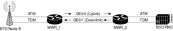
Asymmetric PWE3 Configuration
The following example shows an Asymmetric PWE3 configuration (Figure 22-2).
Figure 22-2 Asymmetric PWE3 Configuration
MWR_1
version 12.4service timestamps debug datetime msec localtimeservice timestamps log datetime msec localtime!hostname MWR1!boot-start-markerboot-end-marker!card type e1 0 0card type e1 0 1!!ip cef!!controller E1 0/0clock source internalcem-group 1 unframed!controller E1 0/1clock source internalcem-group 20 unframed!controller E1 0/2clock source internalcem-group 12 unframed!controller E1 0/3clock source internalcem-group 30 unframed!controller E1 0/4clock source internalcem-group 8 unframed!controller E1 0/5clock source internalcem-group 25 unframed!controller E1 1/0mode atmclock source internal!controller E1 1/1mode atmclock source internal!controller E1 1/2mode atmclock source internal!controller E1 1/3!!pseudowire-class mplsencapsulation mplspreferred-path peer 50.0.0.2!!interface Loopback50ip address 50.0.0.1 255.255.255.255!interface CEM0/0no ip addresscem 1xconnect 50.0.0.2 1 encapsulation mpls!!interface Vlan 20ip address 20.0.0.1 255.0.0.0mpls ip!interface CEM0/1no ip addresscem 20xconnect 50.0.0.2 2 encapsulation mpls!interface Vlan 60ip address 60.0.0.1 255.0.0.0mpls ip!interface CEM0/2no ip addresscem 12xconnect 50.0.0.2 3 encapsulation mpls!!interface CEM0/3no ip addresscem 30xconnect 50.0.0.2 4 encapsulation mpls!interface CEM0/4no ip addresscem 8xconnect 50.0.0.2 5 encapsulation mpls!!interface CEM0/5no ip addresscem 25xconnect 50.0.0.2 6 encapsulation mpls!interface GigabitEthernet0/0switchport access vlan 20duplex autospeed auto!interface GigabitEthernet0/1switchport access vlan 60duplex autospeed auto!interface ATM1/0no ip addressload-interval 30scrambling-payloadmcpt-timers 1000 5000 10000no ilmi-keepalivepvc 0/5 l2transportencapsulation aal0cell-packing 10 mcpt-timer 3xconnect 50.0.0.2 10 pw-class mpls!pvc 0/6 l2transportxconnect 50.0.0.2 20 pw-class mpls!pvc 0/7 l2transportencapsulation aal0cell-packing 28 mcpt-timer 3xconnect 50.0.0.2 30 encapsulation mpls pw-class mpls one-to-one!pvc 0/8 l2transportxconnect 50.0.0.2 40 pw-class mpls!pvc 0/9 l2transportencapsulation aal0xconnect 50.0.0.2 50 pw-class mpls one-to-one!!interface ATM1/0.1 point-to-pointpvc 0/15 l2transportxconnect 50.0.0.2 13 pw-class mpls!interface ATM1/0.2 multipointcell-packing 2 mcpt-timer 1xconnect 50.0.0.2 12 encapsulation mplspvc 0/10 l2transportencapsulation aal0!pvc 0/11 l2transportencapsulation aal0!pvc 0/12 l2transportencapsulation aal0!pvc 0/13 l2transportencapsulation aal0!!interface ATM1/0.3 point-to-pointpvc 0/16 l2transportencapsulation aal0xconnect 50.0.0.2 14 encapsulation mpls!!interface ATM1/0.4 point-to-pointpvc 0/17 l2transportencapsulation aal0xconnect 50.0.0.2 15 pw-class mpls one-to-one!!interface ATM1/0.6 multipointpvc 0/26 l2transportxconnect 50.0.0.2 16 pw-class mpls!pvc 0/27 l2transportencapsulation aal0cell-packing 8 mcpt-timer 3xconnect 50.0.0.2 17 pw-class mpls!pvc 0/28 l2transportencapsulation aal0cell-packing 16 mcpt-timer 2xconnect 50.0.0.2 18 pw-class mpls!!interface ATM1/0.7 multipoint!interface ATM1/1no ip addressscrambling-payloadmcpt-timers 1000 5000 10000no ilmi-keepalivecell-packing 20 mcpt-timer 2xconnect 50.0.0.2 11 encapsulation mplspvc 0/21 l2transportencapsulation aal0!pvc 0/22 l2transportencapsulation aal0!pvc 0/23 l2transportencapsulation aal0!!interface ATM1/1.1 point-to-point!interface ATM1/1.2 multipoint!interface ATM1/2no ip addressscrambling-payloadima-group 0no ilmi-keepalive!ip route 50.0.0.2 255.255.255.255 20.0.0.2!ip http serverno ip http secure-server!!mpls ldp router-id Loopback50 force!!line con 0exec-timeout 0 0line aux 0line vty 0 4login!network-clock-select 1 BITS!endMWR_2
version 12.4service timestamps debug datetime msecservice timestamps log datetime msec!hostname MWR2!boot-start-markerboot-end-marker!card type e1 0 0card type e1 0 1!enable password mypassword!no aaa new-model!ip cef!!controller E1 0/0cem-group 1 unframed!controller E1 0/1cem-group 20 unframed!controller E1 0/2cem-group 12 unframed!controller E1 0/3cem-group 30 unframed!controller E1 0/4cem-group 8 unframed!controller E1 0/5cem-group 25 unframed!controller E1 1/0mode atmclock source internal!controller E1 1/1mode atmclock source internal!controller E1 1/2mode atmclock source internal!controller E1 1/3clock source internal!pseudowire-class mplsencapsulation mplspreferred-path peer 50.0.0.1!!interface Loopback50ip address 50.0.0.2 255.255.255.255!interface CEM0/0no ip addresscem 1xconnect 50.0.0.1 1 encapsulation mpls!!interface Vlan20ip address 20.0.0.2 255.0.0.0mpls ip!interface Vlan60ip address 60.0.0.2 255.0.0.0mpls ip!interface GigabitEthernet0/0switchport access vlan 20duplex autospeed auto!interface GigabitEthernet0/1switchport access vlan 60duplex autospeed auto!!interface CEM0/1no ip addresscem 20xconnect 50.0.0.1 2 encapsulation mpls!!interface CEM0/2no ip addresscem 12xconnect 50.0.0.1 3 encapsulation mpls!!interface CEM0/3no ip addresscem 30xconnect 50.0.0.1 4 encapsulation mpls!!interface CEM0/4no ip addresscem 8xconnect 50.0.0.1 5 encapsulation mpls!!interface CEM0/5no ip addresscem 25xconnect 50.0.0.1 6 encapsulation mpls!!interface ATM1/0ip address 1.1.1.2 255.0.0.0load-interval 30scrambling-payloadmcpt-timers 1000 5000 10000no ilmi-keepalivepvc 0/5 l2transportencapsulation aal0cell-packing 25 mcpt-timer 3xconnect 50.0.0.1 10 pw-class mpls!pvc 0/6 l2transportxconnect 50.0.0.1 20 pw-class mpls!pvc 0/7 l2transportencapsulation aal0cell-packing 12 mcpt-timer 2xconnect 50.0.0.1 30 encapsulation mpls pw-class mpls one-to-one!pvc 0/8 l2transportxconnect 50.0.0.1 40 pw-class mpls!pvc 0/9 l2transportencapsulation aal0xconnect 50.0.0.1 50 pw-class mpls one-to-one!pvc 0/99protocol ip 1.1.1.1 broadcastencapsulation aal5snap!!interface ATM1/0.1 point-to-pointpvc 0/15 l2transportxconnect 50.0.0.1 13 pw-class mpls!!interface ATM1/0.2 multipointcell-packing 10 mcpt-timer 2xconnect 50.0.0.1 12 encapsulation mplspvc 0/10 l2transportencapsulation aal0!pvc 0/11 l2transportencapsulation aal0!pvc 0/12 l2transportencapsulation aal0!pvc 0/13 l2transportencapsulation aal0!!interface ATM1/0.3 point-to-pointpvc 0/16 l2transportencapsulation aal0xconnect 50.0.0.1 14 encapsulation mpls!!interface ATM1/0.4 point-to-pointpvc 0/17 l2transportencapsulation aal0xconnect 50.0.0.1 15 pw-class mpls one-to-one!!interface ATM1/0.6 multipointpvc 0/26 l2transportxconnect 50.0.0.1 16 pw-class mpls!pvc 0/27 l2transportencapsulation aal0cell-packing 18 mcpt-timer 3xconnect 50.0.0.1 17 pw-class mpls!pvc 0/28 l2transportencapsulation aal0cell-packing 24 mcpt-timer 2xconnect 50.0.0.1 18 pw-class mpls!!interface ATM1/0.7 multipoint!interface ATM1/1no ip addressscrambling-payloadmcpt-timers 1000 5000 10000no ilmi-keepalivecell-packing 20 mcpt-timer 2xconnect 50.0.0.1 11 encapsulation mplspvc 0/21 l2transportencapsulation aal0!pvc 0/22 l2transportencapsulation aal0!pvc 0/23 l2transportencapsulation aal0!!interface ATM1/2no ip addressscrambling-payloadima-group 0no ilmi-keepalive!ip route 50.0.0.1 255.255.255.255 60.0.0.1!!ip http serverno ip http secure-server!!mpls ldp router-id Loopback50 force!!!line con 0exec-timeout 0 0line aux 0line vty 0 4exec-timeout 0 0login!network-clock-select 1 BITS!endPWE3 Redundancy Configuration
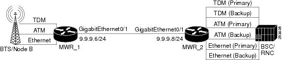
The following example shows a PWE3 Redundancy configuration (Figure 22-3).
Figure 22-3 PWE3 Redundancy Configuration
MWR_1
version 12.4service timestamps debug datetime msecservice timestamps log datetime msec!hostname mwr-1!boot-start-markerboot-end-marker!card type e1 0 1card type e1 0 2!ip cef!controller E1 0/0clock source internalcem-group 0 unframed!controller E1 0/1!controller E1 0/2!controller E1 0/3clock source internal!controller E1 1/0mode atmclock source internal!controller E1 1/1!controller E1 1/2!controller E1 1/3clock source internal!interface CEM0/0cem 0xconnect 2.2.2.2 1 encapsulation mplsbackup peer 2.2.2.2 2backup delay 20 20!interface ATM1/0no ip addressscrambling-payloadno ilmi-keepalivepvc 0/1 l2transportencapsulation aal0xconnect 2.2.2.2 3 encapsulation mplsbackup peer 2.2.2.2 4backup delay 20 20!interface Loopback0no ip address!interface Loopback1ip address 1.1.1.1 255.255.255.255load-interval 30!interface Loopback101no ip address!!interface Vlan 9ip address 9.9.9.6 255.255.255.0mpls ip!interface Vlan 10no ip addressno ptp enablexconnect 2.2.2.2 10 encapsulation mplsbackup peer 2.2.2.2 20!interface GigabitEthernet0/1switchport access vlan 9duplex autospeed auto!interface GigabitEthernet0/2switchport access vlan 10duplex autospeed auto!!ip forward-protocol ndip route 2.2.2.2 255.255.255.255 9.9.9.8!!control-plane!!line con 0exec-timeout 0 0logging synchronousline aux 0line vty 0 4exec-timeout 0 0password mypasswordlogin!exception data-corruption buffer truncate!endMWR_2
!version 12.4service timestamps debug datetime msecservice timestamps log datetime msec!hostname mwr-pe2!boot-start-markerboot-end-marker!card type e1 0 0card type e1 0 1card type e1 0 2!!ip cef!!controller E1 0/0cem-group 0 unframed!controller E1 0/1clock source internalcem-group 0 unframed!controller E1 0/2!controller E1 0/3clock source internal!controller E1 0/4clock source internal!controller E1 0/5!controller E1 1/0mode atmclock source internal!controller E1 1/1clock source internal!controller E1 1/2clock source internal!controller E1 1/3mode atmclock source internal!! Primaryinterface CEM0/0cem 0xconnect 1.1.1.1 1 encapsulation mpls!! Backupinterface CEM0/1cem 0xconnect 1.1.1.1 2 encapsulation mpls!! Primaryinterface ATM1/0no ip addressscrambling-payloadno ilmi-keepalivepvc 0/1 l2transportencapsulation aal0xconnect 1.1.1.1 3 encapsulation mpls!! Backupinterface ATM1/3no ip addressscrambling-payloadno ilmi-keepalivepvc 0/1 l2transportencapsulation aal0xconnect 1.1.1.1 4 encapsulation mpls!!interface Loopback1ip address 2.2.2.2 255.255.255.255!!interface Vlan 9ip address 9.9.9.8 255.255.255.0mpls ip!interface Vlan 10no ip addressno ptp enablexconnect 1.1.1.1 10 encapsulation mpls!interface Vlan 20no ip addressno ptp enablexconnect 1.1.1.1 20 encapsulation mpls!interface GigabitEthernet0/1switchport access vlan 9duplex autospeed auto!interface GigabitEthernet0/2switchport access vlan 10duplex autospeed auto!interface GigabitEthernet0/3switchport access vlan 20duplex autospeed auto!!ip forward-protocol ndip route 1.1.1.1 255.255.255.255 9.9.9.6!!mpls ldp router-id Loopback1 force!control-plane!no call rsvp-sync!!!line con 0exec-timeout 0 0logging synchronousline aux 0line vty 0 4exec-timeout 0 0password mypasswordlogin!exception data-corruption buffer truncate!endTDM over MPLS Configuration
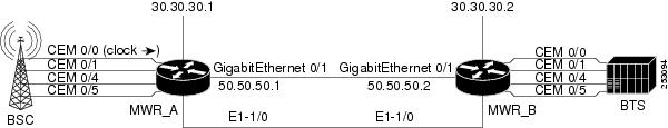
Figure 22-4 shows a TDM over MPLS configuration. The configuration uses both SAToP and CESoPSN for E1 and T1.
Figure 22-4 TDM over MPLS Configuration
MWR_A
!version 12.4service timestamps debug datetime msec localtime show-timezoneservice timestamps log datetime msec localtime show-timezoneno service password-encryption!hostname mwr_A!boot-start-markerboot-end-marker!card type e1 0 0card type e1 0 1enable password xxx!no aaa new-modelclock timezone est -5!ip cef!controller E1 0/0cem-group 0 timeslots 1-31description E1 CESoPSN example!controller E1 0/1clock source internalcem-group 1 unframeddescription E1 SATOP example!controller E1 0/4clock source internalcem-group 4 unframeddescription E1 SATOP example!controller E1 0/5clock source internalcem-group 5 timeslots 1-24description E1 CESoPSN example!controller E1 1/0clock source internal!controller E1 1/1!interface Loopback0ip address 30.30.30.1 255.255.255.255!interface GigabitEthernet0/1ip address 50.50.50.1 255.255.255.0mpls ip!interface CEM0/0no ip addresscem 0xconnect 30.30.30.2 300 encapsulation mpls!interface CEM0/1no ip addresscem 1xconnect 30.30.30.2 301 encapsulation mpls!!interface CEM0/4no ip addresscem 4xconnect 30.30.30.2 304 encapsulation mpls!!interface CEM0/5no ip addresscem 5xconnect 30.30.30.2 305 encapsulation mpls!!no ip classlessip route 30.30.30.2 255.255.255.255 50.50.50.2!no ip http serverno ip http secure-server!line con 0password xxxloginline aux 0password xxxloginno execline vty 0 4password xxxlogin!network-clock-select 1 BITSendMWR_B
!version 12.4service timestamps debug datetime msec localtime show-timezoneservice timestamps log datetime msec localtime show-timezoneno service password-encryption!hostname mwr_B!boot-start-markerboot-end-marker!card type e1 0 0card type e1 0 1enable password xxx!no aaa new-modelclock timezone est -5!ip cef!controller E1 0/0clock source internalcem-group 0 timeslots 1-31description E1 CESoPSN example!controller E1 0/1clock source internalcem-group 1 unframeddescription E1 SATOP example!controller E1 0/4clock source internalcem-group 4 unframeddescription T1 SATOP example!controller E1 0/5clock source internalcem-group 5 timeslots 1-24description T1 CESoPSN example!controller E1 1/0!controller E1 1/1!interface Loopback0ip address 30.30.30.2 255.255.255.255!!interface GigabitEthernet0/1ip address 50.50.50.2 255.255.255.0mpls ip!interface CEM0/0no ip addresscem 0xconnect 30.30.30.1 300 encapsulation mpls!interface CEM0/1no ip addresscem 1xconnect 30.30.30.1 301 encapsulation mpls!interface CEM0/4no ip addresscem 4xconnect 30.30.30.1 304 encapsulation mpls!!interface CEM0/5no ip addresscem 5xconnect 30.30.30.1 305 encapsulation mpls!!no ip classlessip route 30.30.30.1 255.255.255.255 50.50.50.1!no ip http serverno ip http secure-server!line con 0password xxxloginline aux 0password xxxloginno execline vty 0 4password xxxlogin!network-clock-select 1 E1 1/0endCESoPSN with UDP Configuration
The following configuration uses CESoSPN with UDP encapsulation.
Note
interface Loopback0ip address 2.2.2.8 255.255.255.255!pseudowire-class udpClassencapsulation udpprotocol noneip local interface Loopback 0!controller E1 0/13clock source internalcem-group 0 timeslots 1-31!interface cem 0/13cem 0xconnect 2.2.2.9 200 pw-class udpClassudp port local 50000 remote 55000ATM over MPLS Configuration
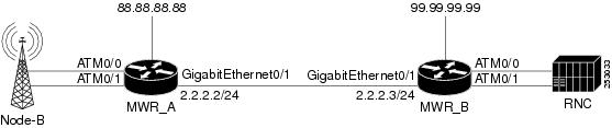
This example shows how to accomplish the following configurations (Figure 22-5):
Note
•
•
•
•
•
•
•
Figure 22-5 ATM over MPLS Configuration
MWR_A
!version 12.4service timestamps debug datetime msecservice timestamps log datetime msec!hostname mwr_A!boot-start-markerboot-end-marker!card type e1 0 0card type e1 0 1logging buffered 4096enable password mypassword!!ip cef!!no ip domain lookup!!controller E1 0/0mode atmclock source internal!controller E1 0/1mode atmclock source internal!controller E1 0/2mode atmclock source internal!controller E1 0/3mode atmclock source internal!controller E1 0/4!controller E1 0/5!controller E1 1/0!controller E1 1/1!pseudowire-class mpls-exp-5encapsulation mplsmpls experimental 5!!interface Loopback0ip address 88.88.88.88 255.255.255.255!interface ATM0/0no ip addressscrambling-payloadmcpt-timers 1000 2000 3000no ilmi-keepalivecell-packing 28 mcpt-timer 3xconnect 99.99.99.99 100 encapsulation mplspvc 1/35 l2transportencapsulation aal0!pvc 1/36 l2transportencapsulation aal0!pvc 1/37 l2transportencapsulation aal0!interface GigabitEthernet0/0!interface ATM0/1no ip addressload-interval 30scrambling-payloadmcpt-timers 1000 2000 3000no ilmi-keepalivepvc 0/10!pvc 0/100 l2transportencapsulation aal5xconnect 99.99.99.99 1100 encapsulation mpls!pvc 0/101 l2transportencapsulation aal0cell-packing 28 mcpt-timer 3xconnect 99.99.99.99 1101 encapsulation mpls!pvc 0/102 l2transportencapsulation aal0cell-packing 28 mcpt-timer 3xconnect 99.99.99.99 1102 encapsulation mpls!pvc 0/103 l2transportencapsulation aal0cell-packing 28 mcpt-timer 3xconnect 99.99.99.99 1103 pw-class mpls-exp-5!!interface ATM0/1.1 multipointcell-packing 28 mcpt-timer 3xconnect 99.99.99.99 1200 encapsulation mplspvc 1/35 l2transportencapsulation aal0pw-pvc 2/135!pvc 1/36 l2transportencapsulation aal0pw-pvc 2/136!pvc 1/37 l2transportencapsulation aal0pw-pvc 2/137!!interface GigabitEthernet0/1description interface to 7600 fas 3/5ip address 2.2.2.2 255.255.255.0duplex autospeed autompls ipno keepalive!interface ATM0/2no ip addressscrambling-payloadno ilmi-keepalive!interface ATM0/3no ip addressscrambling-payloadno ilmi-keepalive!ip route 99.99.99.99 255.255.255.255 2.2.2.3!!ip http serverno ip http secure-server!!mpls ldp router-id Loopback0!!line con 0exec-timeout 0 0line aux 0line vty 0 4exec-timeout 0 0privilege level 15password mypasswordlogin!network-clock-select 1 E1 1/0!endMWR_B
!version 12.4service timestamps debug datetime msecservice timestamps log datetime msec!hostname mwr_B!boot-start-markerboot-end-marker!card type e1 0 0card type e1 0 1logging buffered 4096enable password mypassword!!ip cef!!no ip domain lookup!!controller E1 0/0mode atm!controller E1 0/1mode atm!controller E1 0/2mode atm!controller E1 0/3mode atm!controller E1 0/4!controller E1 0/5!pseudowire-class mpls-exp-5encapsulation mplsmpls experimental 5!!interface Loopback0ip address 99.99.99.99 255.255.255.255!interface ATM0/0no ip addressscrambling-payloadmcpt-timers 1000 2000 3000no ilmi-keepalivecell-packing 28 mcpt-timer 3xconnect 88.88.88.88 100 encapsulation mplspvc 1/35 l2transportencapsulation aal0!pvc 1/36 l2transportencapsulation aal0!pvc 1/37 l2transportencapsulation aal0!!interface GigabitEthernet0/0!interface ATM0/1no ip addressscrambling-payloadmcpt-timers 1000 2000 3000no ilmi-keepalivepvc 0/2!pvc 0/100 l2transportencapsulation aal5xconnect 88.88.88.88 1100 encapsulation mpls!pvc 0/101 l2transportencapsulation aal0cell-packing 28 mcpt-timer 3xconnect 88.88.88.88 1101 encapsulation mpls!pvc 0/102 l2transportencapsulation aal0cell-packing 28 mcpt-timer 3xconnect 88.88.88.88 1102 encapsulation mpls!pvc 0/103 l2transportencapsulation aal0cell-packing 28 mcpt-timer 3xconnect 88.88.88.88 1103 pw-class mpls-exp-5!interface ATM0/1.1 multipointcell-packing 28 mcpt-timer 3xconnect 88.88.88.88 1200 encapsulation mplspvc 2/135 l2transportencapsulation aal0!pvc 2/136 l2transportencapsulation aal0!pvc 2/137 l2transportencapsulation aal0!!interface GigabitEthernet0/1ip address 2.2.2.3 255.255.255.0duplex autospeed autompls ip!interface ATM0/2no ip addressscrambling-payloadima-group 0no ilmi-keepalive!interface ATM0/3no ip addressscrambling-payloadima-group 0no ilmi-keepalive!ip route 88.88.88.88 255.255.255.255 2.2.2.2!!ip http serverno ip http secure-server!!mpls ldp router-id Loopback0!!line con 0exec-timeout 0 0line aux 0line vty 0 4exec-timeout 0 0password mypasswordlogin!network-clock-select 1 E1 0/0!endEthernet over MPLS Configuration
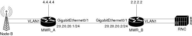
The following configuration example shows an Ethernet pseudowire (aka EoMPLS) configuration.
MWR_A
!version 12.4service timestamps debug datetime msecservice timestamps log datetime msecno service password-encryption!hostname mwr_A!boot-start-markerboot-end-marker!card type e1 0 0card type e1 0 1logging buffered 4096enable password mypassword!no aaa new-model!network-clock-select 1 E1 0/0mmi polling-interval 60no mmi auto-configureno mmi pvcmmi snmp-timeout 180ip cef!no ip domain lookupip domain name cisco.commultilink bundle-name authenticatedmpls label protocol ldpvpdn enable!!controller E1 0/0mode aim 1!controller E1 0/1mode aim 1!controller E1 0/2mode aim 1!controller E1 0/3mode aim 1!controller E1 0/4!controller E1 0/5!interface Loopback0ip address 4.4.4.4 255.255.255.255!interface GigabitEthernet0/4switchport trunk allowed vlan 1,2,20,1002-1005switchport mode trunk!interface GigabitEthernet0/5switchport trunk allowed vlan 1,2,40,1002-1005switchport mode trunk!interface Vlan20ip address 20.20.20.1 255.255.255.0no ptp enablempls ip!interface Vlan40no ip addressno ptp enablexconnect 2.2.2.2 10 encapsulation mpls!ip route 2.2.2.2 255.255.255.255 20.20.20.2!no ip http serverno ip http secure-server!!mpls ldp router-id Loopback0!!line con 0exec-timeout 0 0line aux 0line vty 0 4exec-timeout 0 0password mypasswordlogin!endMWR_B
!version 12.4service timestamps debug datetime msecservice timestamps log datetime msecno service password-encryption!hostname mwr_B!boot-start-markerboot-end-marker!card type e1 0 0card type e1 0 1logging buffered 4096enable password mypassword!no aaa new-model!network-clock-select 1 E1 0/0mmi polling-interval 60no mmi auto-configureno mmi pvcmmi snmp-timeout 180ip cef!no ip domain lookupip domain name cisco.commultilink bundle-name authenticatedmpls label protocol ldpvpdn enable!!controller E1 0/0mode aim 1!controller E1 0/1mode aim 1!controller E1 0/2mode aim 1!controller E1 0/3mode aim 1!controller E1 0/4!controller E1 0/5!interface Loopback0ip address 2.2.2.2 255.255.255.255!interface GigabitEthernet0/4switchport trunk allowed vlan 1,2,20,1002-1005switchport mode trunk!interface GigabitEthernet0/5switchport trunk allowed vlan 1,2,40,1002-1005switchport mode trunk!interface Vlan20ip address 20.20.20.2 255.255.255.0no ptp enablempls ip!interface Vlan40no ip addressno ptp enablexconnect 4.4.4.4 10 encapsulation mpls!ip route 4.4.4.4 255.255.255.255 20.20.20.1!no ip http serverno ip http secure-server!!mpls ldp router-id Loopback0!!line con 0exec-timeout 0 0line aux 0line vty 0 4exec-timeout 0 0password mypasswordlogin!end