-
Cisco MWR 2941 Mobile Wireless Edge Router Software Configuration Guide, Release 15.0(1)MR
-
About This Guide
-
Cisco MWR 2941 Router Overview
-
Cisco IOS Software Basics
-
First-Time Configuration
-
Configuring Gigabit Ethernet Interfaces
-
Configuring Layer 2 Interfaces
-
Configuring HWIC-9ESW Interfaces
-
Configuring VLANs
-
Configuring IEEE 802.1Q Tunneling, VLAN Mapping, 802.1ad, and Layer 2 Protocol Tunneling
-
Configuring STP
-
Configuring MSTP
-
Configuring Optional Spanning-Tree Features
-
Managing the MAC Address Table
-
Configuring Cisco Express Forwarding
-
Configuring Resilient Ethernet Protocol
-
Configuring Ethernet Link Operations, Administration, and Maintenance
-
Configuring Clocking and Timing
-
Configuring Synchronous Ethernet ESMC and SSM
-
Configuring MLPPP Backhaul
-
Configuring Multiprotocol Label Switching
-
Configuring Routing Protocols
-
Configuring Bidirectional Forwarding Detection
-
Configuring Pseudowire
-
Configuring Layer 3 Virtual Private Networks
-
Configuring Quality of Service
-
Configuring Link Noise Monitor
-
Configuring Cisco Discovery Protocol
-
Monitoring and Managing the Cisco MWR 2941 Router
-
Index
-
 Feedback
Table Of Contents
Configuring IEEE 802.1Q Tunneling and Layer 2 Protocol Tunneling
Understanding 802.1Q Tunneling
Default 802.1Q Tunneling Configuration
802.1Q Tunneling Configuration Guidelines
802.1Q Tunneling and Other Features
Routing on VLANs with 802.1Q Tunnel Ports
Configuring an 802.1Q Tunneling Port
Mapping Customer VLANs to Service-Provider VLANs
Default VLAN Mapping Configuration
VLAN Mapping Configuration Guidelines
Configuring Traditional QinQ on an 802.1Q Tunnel Port
Configuring Selective QinQ on a Tunnel Port
Understanding Layer 2 Protocol Tunneling
Configuring Layer 2 Protocol Tunneling
Default Layer 2 Protocol Tunneling Configuration
Layer 2 Protocol Tunneling Configuration Guidelines
Configuring Layer 2 Protocol Tunneling
Monitoring and Maintaining Tunneling and Mapping Status
Configuring IEEE 802.1Q Tunneling and Layer 2 Protocol Tunneling
VPNs provide enterprise-scale connectivity on a shared infrastructure, often Ethernet-based, with the same security, prioritization, reliability, and manageability requirements of private networks. Tunneling is a feature designed for service providers who carry traffic of multiple customers across their networks and are required to maintain the VLAN and Layer 2 protocol configurations of each customer without impacting the traffic of other customers. The Cisco MWR 2941 router supports IEEE 802.1Q tunneling and Layer 2 protocol tunneling.
Note
Release 15.0(1)MR does not support the 802.1ad standard.
Note
•
•
•
•
Understanding 802.1Q Tunneling
Business customers of service providers often have specific requirements for VLAN IDs and the number of VLANs to be supported. The VLAN ranges required by different customers in the same service-provider network might overlap, and traffic of customers through the infrastructure might be mixed. Assigning a unique range of VLAN IDs to each customer would restrict customer configurations and could easily exceed the VLAN limit (4096) of the 802.1Q specification.
Using the 802.1Q tunneling (QinQ) feature, service providers can use a single VLAN to support customers who have multiple VLANs. Customer VLAN IDs (C-VLANs) are preserved, and traffic from different customers is segregated within the service-provider network, even when they appear to be in the same VLAN. Using 802.1Q tunneling expands VLAN space by using a VLAN-in-VLAN hierarchy and retagging the tagged packets. A port configured to support 802.1Q tunneling is called a tunnel port. When you configure tunneling, you assign a tunnel port to a VLAN ID that is dedicated to tunneling. Each customer requires a separate service-provider VLAN ID (S-VLAN), but that VLAN ID supports all of the customer's VLANs. Configuring 802.1Q tunneling on a tunnel port is referred to as traditional QinQ.
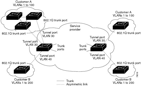
Customer traffic tagged in the normal way with appropriate VLAN IDs comes from an 802.1Q trunk port on the customer device and into a tunnel port on the service-provider edge switch. The link between the customer device and the edge switch is asymmetric because one end is configured as an 802.1Q trunk port, and the other end is configured as a tunnel port. You assign the tunnel port interface to an access VLAN ID that is unique to each customer. See Figure 8-1.
Figure 8-1 802.1Q Tunnel Ports in a Service-Provider Network
Packets coming from the customer trunk port into the tunnel port on the service-provider edge switch are normally 802.1Q-tagged with the appropriate VLAN ID. The the tagged packets remain intact inside the switch and when they exit the trunk port into the service-provider network, they are encapsulated with another layer of an 802.1Q tag (called the metro tag) that contains the VLAN ID that is unique to the customer. The original customer 802.1Q tag is preserved in the encapsulated packet. Therefore, packets entering the service-provider network are double-tagged, with the outer (metro) tag containing the customer's access VLAN ID, and the inner VLAN ID being that of the incoming traffic.
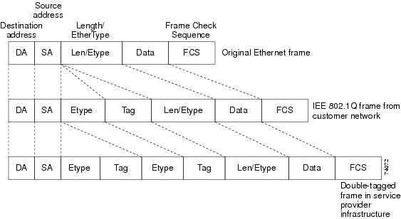
When the double-tagged packet enters another trunk port in a service-provider core switch, the outer tag is stripped as the switch processes the packet. When the packet exits another trunk port on the same core switch, the same metro tag is again added to the packet. Figure 8-2 shows the tag structures of the double-tagged packets.
Note
Figure 8-2 Original (Normal), 802.1Q, and Double-Tagged Ethernet Packet Formats
When the packet enters the trunk port of the service-provider egress switch, the outer tag is again stripped as the switch internally processes the packet. However, the metro tag is not added when the packet is sent out the tunnel port on the edge switch into the customer network. The packet is sent as a normal 802.1Q-tagged frame to preserve the original VLAN numbers in the customer network.
In Figure 8-1, Customer A was assigned VLAN 30, and Customer B was assigned VLAN 40. Packets entering the edge switch tunnel ports with 802.1Q tags are double-tagged when they enter the service-provider network, with the outer tag containing VLAN ID 30 or 40, appropriately, and the inner tag containing the original VLAN number, for example, VLAN 100. Even if both Customers A and B have VLAN 100 in their networks, the traffic remains segregated within the service-provider network because the outer tag is different. Each customer controls its own VLAN numbering space, which is independent of the VLAN numbering space used by other customers and the VLAN numbering space used by the service-provider network.
At the outbound tunnel port, the original VLAN numbers on the customer's network are recovered. It is possible to have multiple levels of tunneling and tagging.
Note
If traffic coming from a customer network is not tagged (native VLAN frames), these packets are bridged or routed as normal packets. All packets entering the service-provider network through a tunnel port on an edge switch are treated as untagged packets, whether they are untagged or already tagged with 802.1Q headers. The packets are encapsulated with the metro tag VLAN ID (set to the access VLAN of the tunnel port) when they are sent through the service-provider network on an 802.1Q trunk port. The priority field on the metro tag is set to match the CoS field of the inner tag (or customer tag) by default.
Configuring 802.1Q Tunneling
•
•
•
•
Default 802.1Q Tunneling Configuration
By default, 802.1Q tunneling is disabled because the default switchport mode is access. Tagging of 802.1Q native VLAN packets on all 802.1Q trunk ports is also disabled. By default, VLANs on the router are dot1q tunnel ports.
802.1Q Tunneling Configuration Guidelines
When you configure 802.1Q tunneling, you should always use an asymmetrical link between the customer device and the edge switch, with the customer device port configured as an 802.1Q trunk port and the edge switch port configured as a tunnel port.
Assign tunnel ports only to VLANs that are used for tunneling.
The following sections explain the configuration requirements for native VLANs and maximum transmission units (MTUs).
Native VLANs
When configuring 802.1Q tunneling on an edge switch, you must use 802.1Q trunk ports for sending packets into the service-provider network. However, packets going through the core of the service-provider network can be carried through 802.1Q trunks or nontrunking links. When 802.1Q trunks are used in these core switches, the native VLANs of the 802.1Q trunks must not match any native VLAN of the nontrunking (tunneling) port on the same switch because traffic on the native VLAN would not be tagged on the 802.1Q sending trunk port.
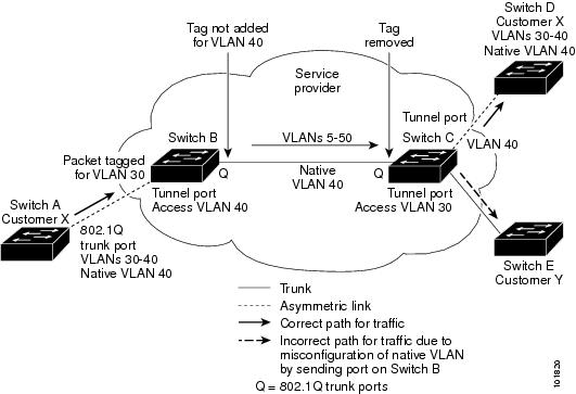
See Figure 8-3. VLAN 40 is configured as the native VLAN for the 802.1Q trunk port from Customer X at the ingress edge switch in the service-provider network (Switch B). Switch A of Customer X sends a tagged packet on VLAN 30 to the ingress tunnel port of Switch B in the service-provider network, which belongs to access VLAN 40. Because the access VLAN of the tunnel port (VLAN 40) is the same as the native VLAN of the edge-switch trunk port (VLAN 40), the metro tag is not added to tagged packets received from the tunnel port. The packet carries only the VLAN 30 tag through the service-provider network to the trunk port of the egress-edge switch (Switch C) and is misdirected through the egress switch tunnel port to Customer Y.
These are some ways to solve this problem:
•
Note
•
•
Figure 8-3 Potential Problem with 802.1Q Tunneling and Native VLANs
System MTU
The default MTU size for Gigabit Ethernet ports is 9216 bytes and is a fixed value. Release 15.0(1)MR does not support the system mtu or system mtu jumbo command.
802.1Q Tunneling and Other Features
Although 802.1Q tunneling works well for Layer 2 packet switching, there are incompatibilities between some Layer 2 features and Layer 3 switching.
Routing on VLANs with 802.1Q Tunnel Ports
IP routing is not supported on a VLAN that includes 802.1Q tunnel ports. Packets received from a tunnel port are forwarded based only on Layer 2 information. The Cisco MWR 2941 does not support routing on switch virtual interfaces (SVIs).
Configuring an 802.1Q Tunneling Port
Beginning in privileged EXEC mode, follow these steps to configure a port as an 802.1Q tunnel port:
Use the no switchport mode dot1q-tunnel interface configuration command to return the port to the default state of access. Use the no vlan dot1q tag native global configuration command to disable tagging of native VLAN packets.
This example shows how to configure an interface as a tunnel port, enable tagging of native VLAN packets, and verify the configuration. In this configuration, the VLAN ID for the customer connected to Gigabit Ethernet interface 2 is VLAN 22.
Router(config)# interface gigabitethernet0/2Router(config-if)# switchport access vlan 22% Access VLAN does not exist. Creating vlan 22Router(config-if)# switchport mode dot1q-tunnelRouter(config-if)# exitRouter(config)# vlan dot1q tag nativeRouter(config)# endRouter# show dot1q-tunnel interface gigabitethernet0/2dot1q-tunnel mode LAN Port(s) ----------------------------- Gi0/1Router# show vlan dot1q tag nativedot1q native vlan tagging is enabledThere is no special configuration for provider trunk ports if the S-tags (outer VLAN tags) used in the provider network have a TPID of 0x8100, the TPID used in 802.1Q tags. The provider trunk ports are configured as normal trunk mode switch ports. If one of the other well known tunneling TPIDs is required the dot1q tunneling ethertype tpid interface configuration mode command is used to change it. Valid values for tpid are 0x88A8 (IEEE 802.1ad), 0x9100 and 0x9200. Use the no form of this command to set the TPID back to the default setting of 0x8100.
Note
Understanding VLAN Mapping
Another way to establish S-VLANs is to configure VLAN mapping (or VLAN ID translation) on trunk ports connected to a customer network to map customer VLANs to service-provider VLANs. Packets entering the port are mapped to a service provider VLAN (S-VLAN) based on the port number and the original customer VLAN-ID (C-VLAN) of the packet. Because the VLAN ID is mapped to the S-VLAN on ingress, all forwarding operations are performed based on S-VLAN information.
Note
Note
On an interface configured for VLAN mapping, the specified C-VLAN packets are mapped to the specified S-VLAN when they enter the port. Symmetrical mapping back to the customer C-VLAN occurs when packets exit the port.
There are three types of VLAN mapping on 802.1q tunnel ports:
•
•
•
Untagged packets enter the router on the trunk with the native VLAN and are not mapped.
Note
Note
For information about Quality of Service, see the Release Notes for Cisco MWR 2941 Mobile Wireless Edge Router for Cisco IOS Release 15.0(1)MR and Chapter 24 "Configuring Quality of Service."
Mapping Customer VLANs to Service-Provider VLANs
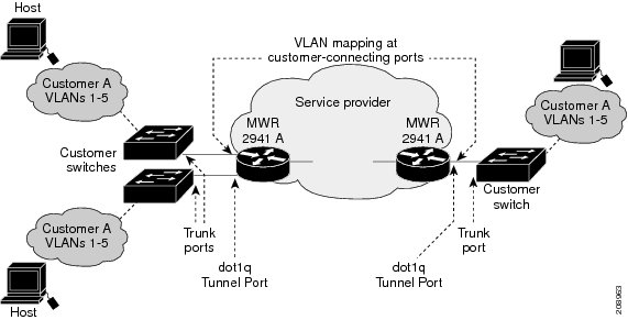
Figure 8-4 shows a topology where a customer uses the same VLANs in multiple sites on different sides of a service-provider network. You map the customer VLAN IDs to service-provider VLAN IDs for packet travel across the service-provider backbone. The customer VLAN IDs are retrieved at the other side of the service-provider backbone for use in the other customer site. Configure the same set of VLAN mappings at a customer-connected port on each side of the service-provider network.
See the examples following the configuration steps for using one-to-one mapping, traditional QinQ, or selective QinQ to map customer VLANs 1 to 5 to service-provider VLANs.
Figure 8-4 Mapping Customer VLANs
Configuring VLAN Mapping
•
•
Default VLAN Mapping Configuration
By default, no VLAN mapping is configured.
VLAN Mapping Configuration Guidelines
•
•
•
Configuring VLAN Mapping
These procedures show how to configure each type of VLAN mapping on trunk ports. To verify your configuration, enter the show running-config interface privileged EXEC command with the interface type number keyword. See the "Monitoring and Maintaining Tunneling and Mapping Status" section for the syntax of these commands. For more information about all commands in this section, see the Cisco MWR 2941 Mobile Wireless Edge Router IOS Command Reference, Release 15.0(1)MR.
Configuring Traditional QinQ on an 802.1Q Tunnel Port
Beginning in privileged EXEC mode, follow these steps to configure VLAN mapping for traditional QinQ on a tunnel port or tunneling by default. Configuring tunneling by default bundles all packets on the port into the configured S-VLAN.
This example shows how to bundle all traffic on the port to leave the router with the S-VLAN ID of 100.
Router(config)# interface gigabiethernet0/1Router(config-if)# switchport mode dot1q-tunnelRouter(config-if)# switchport access vlan 100Router(config-if)# exitConfiguring Selective QinQ on a Tunnel Port
Beginning in privileged EXEC mode, follow these steps to configure VLAN mapping for selective QinQ on a trunk port. Note that you can configure one-to-one mapping and selective QinQ on the same interface, but you cannot use the same C-VLAN IDs in both configurations.
Use the no switchport vlan mapping vlan-id outer vlan-id command to remove the VLAN mapping configuration. Entering no switchport vlan mapping all deletes all mapping configurations.
This example shows how to configure selective QinQ mapping on the port so that traffic with a C-VLAN ID of 1 to 5 enters the router with an S-VLAN ID of 100. The traffic of any other VLAN IDs is tagged as VLAN 123.
Router(config)# interface gigabiethernet0/1Router(config-if)# switchport mode dot1q-tunnelRouter(config-if)# switchport access vlan 123Router(config-if)# switchport vlan mapping 1 100Router(config-if)# switchport vlan mapping 2 100Router(config-if)# switchport vlan mapping 3 100Router(config-if)# switchport vlan mapping 4 100Router(config-if)# switchport vlan mapping 5 100Router(config-if)# exitUnderstanding Layer 2 Protocol Tunneling
Customers at different sites connected across a service-provider network need to use various Layer 2 protocols to scale their topologies to include all remote sites, as well as the local sites. STP must run properly, and every VLAN should build a proper spanning tree that includes the local site and all remote sites across the service-provider network. Cisco Discovery Protocol (CDP) must discover neighboring Cisco devices from local and remote sites. VLAN Trunking Protocol (VTP) must provide consistent VLAN configuration throughout all sites in the customer network that are participating in VTP.
When protocol tunneling is enabled, edge switches on the inbound side of the service-provider network encapsulate Layer 2 protocol packets with a special MAC address and send them across the service-provider network. Core switches in the network do not process these packets but forward them as normal packets. Layer 2 protocol data units (PDUs) for CDP, STP, or VTP cross the service-provider network and are delivered to customer switches on the outbound side of the service-provider network. Identical packets are received by all customer ports on the same VLANs with these results:
•
•
•
Note
Layer 2 protocol tunneling can be used independently or can enhance 802.1Q tunneling. If protocol tunneling is not enabled on 802.1Q tunneling ports, remote switches at the receiving end of the service-provider network do not receive the PDUs and cannot properly run STP, CDP, and VTP. When protocol tunneling is enabled, Layer 2 protocols within each customer's network are totally separate from those running within the service-provider network. Customer switches on different sites that send traffic through the service-provider network with 802.1Q tunneling achieve complete knowledge of the customer's VLAN. If 802.1Q tunneling is not used, you can still enable Layer 2 protocol tunneling by connecting to the customer switch through access or trunk ports and enabling tunneling on the service-provider access or trunk port.
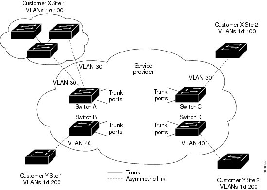
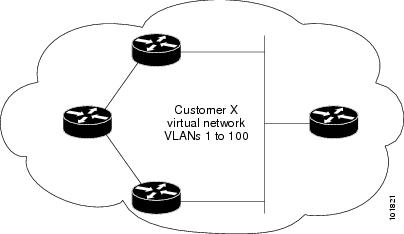
For example, in Figure 8-5, Customer X has four switches in the same VLAN, that are connected through the service-provider network. If the network does not tunnel PDUs, switches on the far ends of the network cannot properly run STP, CDP, and VTP. For example, STP for a VLAN on a switch in Customer X, Site 1, will build a spanning tree on the switches at that site without considering convergence parameters based on Customer X's switch in Site 2. This could result in the topology shown in Figure 8-6.
Figure 8-5 Layer 2 Protocol Tunneling
Figure 8-6 Layer 2 Network Topology without Proper Convergence
Configuring Layer 2 Protocol Tunneling
You can enable Layer 2 protocol tunneling (by protocol) on the ports that are connected to the customer in the edge switches of the service-provider network. The service-provider edge switches connected to the customer switch perform the tunneling process. Edge-switch tunnel ports are connected to customer 802.1Q trunk ports. Edge-switch access ports are connected to customer access ports. The edge switches connected to the customer switch perform the tunneling process.
You can enable Layer 2 protocol tunneling on ports that are configured as access ports, tunnel ports, or trunk ports. The switch supports Layer 2 protocol tunneling for CDP, STP, and VTP. The switch does not support PAgP, LACP, and UDLD protocols for emulated point-to-point network topologies or Layer 2 protocol tunneling for LLDP.
When the Layer 2 PDUs that entered the service-provider inbound edge switch through a Layer 2 protocol-enabled port exit through the trunk port into the service-provider network, the switch overwrites the customer PDU-destination MAC address with a well-known Cisco proprietary multicast address (01-00-0c-cd-cd-d0). If 802.1Q tunneling is enabled, packets are also double-tagged; the outer tag is the customer metro tag, and the inner tag is the customer's VLAN tag. The core switches ignore the inner tags and forward the packet to all trunk ports in the same metro VLAN. The edge switches on the outbound side restore the proper Layer 2 protocol and MAC address information and forward the packets to all Layer 2 protocol-enabled access ports, tunnel ports, and trunk ports in the same metro VLAN. Therefore, the Layer 2 PDUs remain intact and are delivered across the service-provider infrastructure to the other side of the customer network.
See Figure 8-5, with Customer X and Customer Y in access VLANs 30 and 40, respectively. Asymmetric links connect the customers in Site 1 to edge switches in the service-provider network. The Layer 2 PDUs (for example, BPDUs) coming into Switch B from Customer Y in Site 1 are forwarded to the infrastructure as double-tagged packets with the well-known MAC address as the destination MAC address. These double-tagged packets have the metro VLAN tag of 40, as well as an inner VLAN tag (for example, VLAN 100). When the double-tagged packets enter Switch D, the outer VLAN tag 40 is removed, the well-known MAC address is replaced with the respective Layer 2 protocol MAC address, and the packet is sent to Customer Y on Site 2 as a single-tagged frame in VLAN 100.
You can also enable Layer 2 protocol tunneling on access ports on the edge switch connected to access or trunk ports on the customer switch. In this case, the encapsulation and decapsulation process is the same as described in the previous paragraph, except that the packets are not double-tagged in the service-provider network. The single tag is the customer-specific access VLAN tag.
These sections contain this configuration information:
•
•
•
Default Layer 2 Protocol Tunneling Configuration
Table 8-1 shows the default Layer 2 protocol tunneling configuration.
Layer 2 Protocol Tunneling Configuration Guidelines
These are some configuration guidelines and operating characteristics of Layer 2 protocol tunneling:
•
•
•
•
•
•
•
•
Configuring Layer 2 Protocol Tunneling
Beginning in privileged EXEC mode, follow these steps to configure a port for Layer 2 protocol tunneling:
Use the no l2protocol-tunnel [cdp | stp | vtp] interface configuration command to disable protocol tunneling for one of the Layer 2 protocols or for all three. Use the no l2protocol-tunnel shutdown-threshold [cdp | stp | vtp] and the no l2protocol-tunnel drop-threshold [cdp | stp | vtp] commands to return the shutdown and drop thresholds to the default settings.
This example shows how to configure Layer 2 protocol tunneling for CDP, STP, and VTP and to verify the configuration.
Router(config)# interface gigatethernet0/1Router(config-if)# l2protocol-tunnel cdpRouter(config-if)# l2protocol-tunnel stpRouter(config-if)# l2protocol-tunnel vtpRouter(config-if)# l2protocol-tunnel shutdown-threshold 1500Router(config-if)# l2protocol-tunnel drop-threshold 1000Router(config-if)# exitRouter(config)# l2protocol-tunnel cos 7Router(config)# endRouter# show l2protocolCOS for Encapsulated Packets: 7Port Protocol Shutdown Drop Encapsulation Decapsulation DropThreshold Threshold Counter Counter Counter------- -------- --------- --------- ------------- ------------- -------------Gi 0/1 cdp 1500 1000 2288 2282 0stp 1500 1000 116 13 0vtp 1500 1000 3 67 0Monitoring and Maintaining Tunneling and Mapping Status
Table 8-2 shows the privileged EXEC commands for monitoring and maintaining 802.1Q and Layer 2 protocol tunneling and VLAN mapping.
For detailed information about these displays, see the Cisco MWR 2941 Mobile Wireless Edge Router IOS Command Reference, Release 15.0(1)MR.