-
Cisco MWR 2941 Mobile Wireless Edge Router Software Configuration Guide, Release 15.0(1)MR
-
About This Guide
-
Cisco MWR 2941 Router Overview
-
Cisco IOS Software Basics
-
First-Time Configuration
-
Configuring Gigabit Ethernet Interfaces
-
Configuring Layer 2 Interfaces
-
Configuring HWIC-9ESW Interfaces
-
Configuring VLANs
-
Configuring IEEE 802.1Q Tunneling, VLAN Mapping, 802.1ad, and Layer 2 Protocol Tunneling
-
Configuring STP
-
Configuring MSTP
-
Configuring Optional Spanning-Tree Features
-
Managing the MAC Address Table
-
Configuring Cisco Express Forwarding
-
Configuring Resilient Ethernet Protocol
-
Configuring Ethernet Link Operations, Administration, and Maintenance
-
Configuring Clocking and Timing
-
Configuring Synchronous Ethernet ESMC and SSM
-
Configuring MLPPP Backhaul
-
Configuring Multiprotocol Label Switching
-
Configuring Routing Protocols
-
Configuring Bidirectional Forwarding Detection
-
Configuring Pseudowire
-
Configuring Layer 3 Virtual Private Networks
-
Configuring Quality of Service
-
Configuring Link Noise Monitor
-
Configuring Cisco Discovery Protocol
-
Monitoring and Managing the Cisco MWR 2941 Router
-
Index
-
 Feedback
Table Of Contents
Configuring Resilient Ethernet Protocol
Understanding Resilient Ethernet Protocol
Configuring Resilient Ethernet Protocol (REP)
Configuring the REP Administrative VLAN
Setting Manual Preemption for VLAN Load Balancing
Configuring SNMP Traps for REP
Configuration Examples for REP
Configuring the REP Administrative VLAN: Example
Configuring a REP Interface: Example
Setting the Preemption for VLAN Load Balancing: Example
Configuring SNMP Traps for REP: Example
Monitoring the REP Configuration: Example
Sample MWR 2941 Topology: Example
Configuring Resilient Ethernet Protocol
Resilient Ethernet Protocol (REP) is a Cisco proprietary protocol that provides an alternative to Spanning Tree Protocol (STP) to control network loops, to respond to link failures, and to improve convergence time. REP controls a group of ports connected in a segment, ensures that the segment does not create any bridging loops, and responds to link failures within the segment. REP provides a basis for constructing more complex networks and supports VLAN load balancing.
The following sections describe how to configure REP:
•
Understanding Resilient Ethernet Protocol
•
•
Understanding Resilient Ethernet Protocol
The following sections provide further information about REP:
Overview
A REP segment is a chain of ports connected to each other and configured with a segment ID. Each segment consists of standard (nonedge) segment ports and two user-configured edge ports. A switch can have only two ports belonging to the same segment, and each segment port can have only one external neighbor. A segment can go through a shared medium, but on any link, only two ports can belong to the same segment. REP is supported only on Layer 2 trunk interfaces.
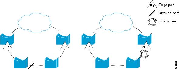
Figure 14-1 shows an example of a segment consisting of six ports spread across four switches. Ports E1 and E2 are configured as edge ports. When all ports are operational (as in the segment on the left), a single port is blocked, shown by the diagonal line. When there is a network failure, as shown in the diagram on the right, the blocked port returns to the forwarding state to minimize network disruption.
Figure 14-1 REP Open Segments
The segment shown in Figure 14-1 is an open segment; there is no connectivity between the two edge ports. The REP segment cannot cause a bridging loop, and you can safely connect the segment edges to any network. All hosts connected to switches inside the segment have two possible connections to the rest of the network through the edge ports, but only one connection is accessible at any time. If a host cannot access its usual gateway because of a failure, REP unblocks all ports to ensure that connectivity is available through the other gateway.
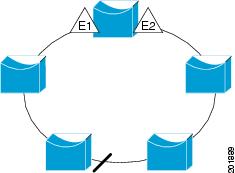
The segment shown in Figure 14-2, with both edge ports located on the same switch, is a ring segment. In this configuration, there is connectivity between the edge ports through the segment. With this configuration, you can create a redundant connection between any two switches in the segment.
Figure 14-2 REP Ring Segment
REP segments have these characteristics:
•
•
•
•
You can construct almost any type of network based on REP segments. REP also supports VLAN load-balancing, controlled by the primary edge port but occurring at any port in the segment.
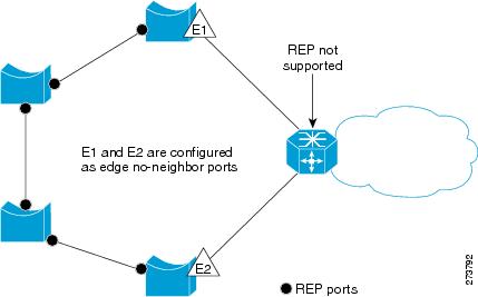
In access ring topologies, the neighboring switch might not support REP, as shown in Figure 14-3. In this case, you can configure the non-REP facing ports (E1 and E2) as edge no-neighbor ports. These ports inherit all properties of edge ports, and you can configure them the same as any edge port, including configuring them to send STP or REP topology change notices to the aggregation switch. In this case the STP topology change notice (TCN) that is sent is a multiple spanning-tree (MST) STP message.
Figure 14-3
No-neighbor Topology
REP has these limitations:
•
•
•
Link Integrity
REP does not use an end-to-end polling mechanism between edge ports to verify link integrity. It implements local link failure detection. The REP Link Status Layer (LSL) detects its REP-aware neighbor and establishes connectivity within the segment. All VLANs are blocked on an interface until it detects the neighbor. After the neighbor is identified, REP determines which neighbor port should become the alternate port and which ports should forward traffic.
Each port in a segment has a unique port ID. The port ID format is similar to that used by the spanning tree algorithm: a port number (unique on the bridge), associated to a MAC address (unique in the network). When a segment port is coming up, its LSL starts sending packets that include the segment ID and the port ID. The port is declared operational after it performs a three-way handshake with a neighbor in the same segment.
A segment port does not become operational if:
•
•
•
Each port creates an adjacency with its immediate neighbor. After the neighbor adjacencies are created, the ports negotiate to determine one blocked port for the segment, the alternate port. All other ports become unblocked. By default, REP packets are sent to a BPDU class MAC address. The packets can also be sent to the Cisco multicast address, which is used only to send blocked port advertisement (BPA) messages when there is a failure in the segment. The packets are dropped by devices not running REP.
Fast Convergence
Because REP runs on a physical link basis and not a per-VLAN basis, only one hello message is required for all VLANs, reducing the load on the protocol. We recommend that you create VLANs consistently on all switches in a given segment and configure the same allowed VLANs on the REP trunk ports. To avoid the delay introduced by relaying messages in software, REP also allows some packets to be flooded to a regular multicast address. These messages operate at the hardware flood layer (HFL) and are flooded to the whole network, not just the REP segment. Switches that do not belong to the segment treat them as data traffic. You can control flooding of these messages by configuring a dedicated administrative VLAN for the whole domain.
The estimated convergence recovery time on fiber interfaces is less than 200 ms for the local segment with 200 VLANs configured. Convergence for VLAN load balancing is 300 ms or less.
VLAN Load Balancing
One edge port in the REP segment acts as the primary edge port; the other as the secondary edge port. The primary edge port always participates in VLAN load balancing in the segment. REP VLAN balancing is achieved by blocking some VLANs at a configured alternate port and all other VLANs at the primary edge port. When you configure VLAN load balancing, you can specify the alternate port in one of three ways:
•
•
Note
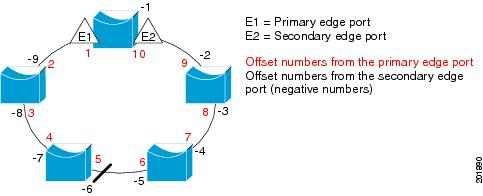
Figure 14-4 shows neighbor offset numbers for a segment where E1 is the primary edge port and E2 is the secondary edge port. The red numbers inside the ring are numbers offset from the primary edge port; the black numbers outside the ring show the offset numbers from the secondary edge port. Note that you can identify all ports (except the primary edge port) by either a positive offset number (downstream position from the primary edge port) or a negative offset number (downstream position from the secondary edge port). If E2 became the primary edge port, its offset number would then be 1, and E1 would be -1.
•
Figure 14-4 Neighbor Offset Numbers in a Segment
When the REP segment is complete, all VLANs are blocked. When you configure VLAN load balancing, you must also configure triggers in one of two ways
•
•
Note
When VLAN load balancing is triggered, the primary edge port sends a message to alert all interfaces in the segment about the preemption. When the secondary port receives the message, it is reflected into the network to notify the alternate port to block the set of VLANs specified in the message and to notify the primary edge port to block the remaining VLANs.
You can also configure a particular port in the segment to block all VLANs. Only the primary edge port initiates VLAN load balancing, which is not possible if the segment is not terminated by an edge port on each end. The primary edge port determines the local VLAN load balancing configuration.
Reconfigure the primary edge port to reconfigure load balancing. When you change the load balancing configuration, the primary edge port again waits for the rep preempt segment command or for the configured preempt delay period after a port failure and recovery before executing the new configuration. If you change an edge port to a regular segment port, the existing VLAN load balancing status does not change. Configuring a new edge port might cause a new topology configuration.
Note
Spanning Tree Interaction
REP does not interact with STP or with the Flex Link feature, but can coexist with both. A port that belongs to a segment is removed from spanning tree control and STP BPDUs are not accepted or sent from segment ports.
To migrate from an STP ring configuration to REP segment configuration, begin by configuring a single port in the ring as part of the segment, and continue by configuring contiguous ports to minimize the number of segments. Each segment always contains a blocked port, so multiple segments means multiple blocked ports and a potential loss of connectivity. When the segment has been configured in both directions to the edge ports, you then configure the edge ports.
REP Ports
Ports in REP segments are Failed, Open, or Alternate.
•
•
•
A regular segment port converted to an edge port, or an edge port converted to a regular segment port, does not always result in a topology change. If you convert an edge port into a regular segment port, VLAN load balancing is not implemented unless it has been configured. For VLAN load balancing, you must configure two edge ports in the segment.
A segment port that is reconfigured as a spanning tree port restarts according the spanning tree configuration. By default, this is a designated blocking port. If PortFast is configured or if STP is disabled, the port goes into the forwarding state.
For instructions on how to configure REP, see Configuring Resilient Ethernet Protocol (REP).
Configuring Resilient Ethernet Protocol (REP)
A segment is a collection of ports connected one to the other in a chain and configured with a segment ID. To configure REP segments, you configure the REP administrative VLAN (or use the default VLAN 1) and then add the ports to the segment using interface configuration mode. You should configure two edge ports in the segment, one as the primary edge port and the other, by default, the secondary edge port. A segment has only one primary edge port. If you configure two ports in a segment as the primary edge port, for example ports on different switches, the REP selects one to serve as the segment primary edge port. You can also optionally configure where to send segment topology change notices (STCNs) and VLAN load balancing messages.
The following sections describe how to configure REP on the Cisco MWR 2941:
•
•
•
Default REP Configuration
REP is disabled on all interfaces. When enabled, the interface is a regular segment port unless it is configured as an edge port.
When REP is enabled, the sending of segment topology change notices (STCNs) is disabled, all VLANs are blocked, and the administrative VLAN is VLAN 1.
When VLAN load balancing is enabled, the default is manual preemption with the delay timer disabled. If VLAN load balancing is not configured, the default after manual preemption is to block all VLANs at the primary edge port.
REP Configuration Guidelines
Follow these guidelines when configuring REP:
•
•
•
•
•
•
•
•
–
–
–
–
•
•
•
•
•
–
–
–
–
•
Configuring the REP Administrative VLAN
To avoid the delay introduced by relaying messages in software for link-failure or VLAN-blocking notification during load balancing, REP floods packets at the hardware flood layer (HFL) to a regular multicast address. These messages are flooded to the whole network, not just the REP segment. You can control flooding of these messages by configuring an administrative VLAN for the whole domain.
Follow these guidelines when configuring the REP administrative VLAN:
•
•
Beginning in privileged EXEC mode, follow these steps to configure the REP administrative VLAN:
Configuring REP Interfaces
For REP operation, you need to enable it on each segment interface and to identify the segment ID. This step is required and must be done before other REP configuration. You must also configure a primary and secondary edge port on each segment. All other steps are optional.
Beginning in privileged EXEC mode, follow these steps to enable and configure REP on an interface:
Setting Manual Preemption for VLAN Load Balancing
If you do not enter the rep preempt delay seconds interface configuration command on the primary edge port to configure a preemption time delay, the default is to manually trigger VLAN load balancing on the segment. Be sure to complete all other segment configuration before manually preempting VLAN load balancing. When you enter the rep preempt segment segment-id command, a confirmation message appears before the command is executed because preemption can cause network disruption.
Note
Beginning in privileged EXEC mode, follow these steps on the switch that has the segment primary edge port to manually trigger VLAN load balancing on a segment:
Configuring SNMP Traps for REP
You can configure the switch to send REP-specific traps to notify the SNMP server of link operational status changes and port role changes. Beginning in privileged EXEC mode, follow these steps to configure REP traps:
Monitoring REP
To monitor the REP configuration, complete the following steps:
Configuration Examples for REP
•
•
•
•
•
•
Configuring the REP Administrative VLAN: Example
This example shows how to configure the administrative VLAN as VLAN 100.
Router# configure terminalRouter(config)# rep admin vlan 100Router(config-if)# endConfiguring a REP Interface: Example
This example shows how to configure an interface as the primary edge port for segment 1, to send Spanning Tree Topology Changes Notification (STCNs) to segments 2 through 5, and to configure the alternate port as the port with port ID 0009001818D68700 to block all VLANs after a preemption delay of 60 seconds after a segment port failure and recovery.
Router# configure terminalRouter(config)# interface gigabitethernet0/1Router(config-if)# rep segment 1 edge primaryRouter(config-if)# rep stcn segment 2-5Router(config-if)# rep block port 0009001818D68700 vlan allRouter(config-if)# rep preempt delay 60Switch (config-if)# rep lsl-age-timer 6000Router(config-if)# endThis example shows how to configure the same configuration when the interface has no external REP neighbor:
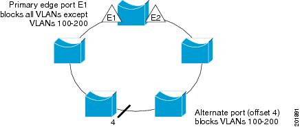
Router# configure terminalRouter(conf)# interface gigabitethernet0/1Router(config-if)# rep segment 1 edge no-neighbor primaryRouter(config-if)# rep stcn segment 2-5Router(config-if)# rep block port 0009001818D68700 vlan allRouter(config-if)# rep preempt delay 60Router(config-if)# rep lsl-age-timer 6000This example shows how to configure the VLAN blocking configuration shown in Figure 5. The alternate port is the neighbor with neighbor offset number 4. After manual preemption, VLANs 100 to 200 are blocked at this port and all other VLANs are blocked at the primary edge port E1 (Gigabit Ethernet port 0/1).
Router# configure terminalRouter(config)# interface gigabitethernet0/1Router(config-if)# rep segment 1 edge primaryRouter(config-if)# rep block port 4 vlan 100-200Router(config-if)# endFigure 5 Example of VLAN Blocking
Setting the Preemption for VLAN Load Balancing: Example
The following is an example of setting the preemption for VLAN load balancing on a REP segment.
Router> enable
Router# configure terminal
Router(config)# rep preempt segment 1
Router(config)# end
Configuring SNMP Traps for REP: Example
This example configures the router to send REP traps at a rate of 10 traps per second:
Router> enableRouter# configure terminalRouter(config)# snmp mib rep trap-rate 10Router(config)# endMonitoring the REP Configuration: Example
The following is sample output of the show interface rep detail command. Use the show interface rep detail command on one of the REP interfaces to monitor and verify the REP configuration.
Router# show interface gigabitethernet0/1 rep detailGigabitEthernet0/1 REP enabled Segment-id: 2 (Edge) PortID: 00010019E7144680 Preferred flag: No Operational Link Status: TWO_WAY Current Key: 0002001121A2D5800E4D Port Role: Open Blocked Vlan: <empty> Admin-vlan: 100 Preempt Delay Timer: disabled Load-balancing block port: none Load-balancing block vlan: none STCN Propagate to: none LSL PDU rx: 3322, tx: 1722 HFL PDU rx: 32, tx: 5 BPA TLV rx: 16849, tx: 508 BPA (STCN, LSL) TLV rx: 0, tx: 0 BPA (STCN, HFL) TLV rx: 0, tx: 0 EPA-ELECTION TLV rx: 118, tx: 118 EPA-COMMAND TLV rx: 0, tx: 0 EPA-INFO TLV rx: 4214, tx: 4190Sample MWR 2941 Topology: Example
The following configuration example shows two Cisco MWR 2941 routers and two Cisco 7600 series routers using a REP ring.
Note
2941_1
interface GigabitEthernet0/0switchport trunk allowed vlan 1,2switchport mode trunkrep segment 1!interface GigabitEthernet0/1switchport trunk allowed vlan 1,2switchport mode trunkrep segment 1!interface GigabitEthernet0/3switchport access vlan 3!interface GigabitEthernet0/4switchport access vlan 4!interface Vlan1ip address 172.18.40.70 255.255.255.128no ptp enable!interface Vlan2ip address 1.1.1.1 255.255.255.0no ptp enable!interface Vlan3ip address 2.2.2.2 255.255.255.0no ptp enable!interface Vlan3ip address 4.4.4.2 255.255.255.0no ptp enable!ip route 3.3.3.0 255.255.255.0 1.1.1.4ip route 5.5.5.0 255.255.255.0 1.1.1.42941_2
interface GigabitEthernet0/0switchport trunk allowed vlan 1,2switchport mode trunkrep segment 1!interface GigabitEthernet0/1switchport trunk allowed vlan 1,2switchport mode trunkrep segment 1!interface Vlan1ip address 172.18.44.239 255.255.255.0no ptp enable!interface Vlan2ip address 1.1.1.2 255.255.255.0no ptp enable7600_1
interface Port-channel69switchportswitchport trunk encapsulation dot1qswitchport trunk allowed vlan 1,2switchport mode trunk!interface GigabitEthernet3/25switchportswitchport trunk encapsulation dot1qswitchport trunk allowed vlan 1,2switchport mode trunkchannel-group 69 mode on!interface GigabitEthernet3/26switchportswitchport trunk encapsulation dot1qswitchport trunk allowed vlan 1,2switchport mode trunkchannel-group 69 mode on!interface GigabitEthernet3/35ip address 3.3.3.2 255.255.255.0!interface GigabitEthernet3/36ip address 5.5.5.2 255.255.255.0!interface GigabitEthernet5/2switchportswitchport trunk encapsulation dot1qswitchport trunk allowed vlan 1,2switchport mode trunkrep segment 1 edge!interface Vlan1no ip address!interface Vlan2ip address 1.1.1.4 255.255.255.0!ip route 2.2.2.0 255.255.255.0 1.1.1.1ip route 4.4.4.0 255.255.255.0 1.1.1.17600_2
interface Port-channel69switchportswitchport trunk encapsulation dot1qswitchport trunk allowed vlan 1,2switchport mode trunk!interface GigabitEthernet5/2switchportswitchport trunk encapsulation dot1qswitchport trunk allowed vlan 1,2switchport mode trunkrep segment 1 edge!interface GigabitEthernet7/25switchportswitchport trunk encapsulation dot1qswitchport trunk allowed vlan 1,2switchport mode trunkchannel-group 69 mode on!interface GigabitEthernet7/26switchportswitchport trunk encapsulation dot1qswitchport trunk allowed vlan 1,2switchport mode trunkchannel-group 69 mode on!interface Vlan1no ip address!interface Vlan2ip address 1.1.1.3 255.255.255.0!