Feedback
Table Of Contents
Introduction to Administration
Administration Section of the Toolbox
Additional Administrative Tools
Introduction to Host Administration
Understanding Host Administration
Creating a New Host Using the Right-Click Copy Option
Understanding Capacity, Limit, and Expense
Assigning Node Attributes to a Host
Introduction to System Administration
Output (System Administration)
General Settings (System Administration)
Status Settings (System Administration)
Data Purging (System Administration)
Audio Capture (System Administration)
Single Node Mode (System Administration)
Grid Computing (System Administration)
Setting Default Copyright Information
Configuring Output File Storage Location
Enabling Sys Admin E-mail Notification
Turning Monitor Display Windows On/Off
Setting the Auto Reap Interval for Job Monitoring
Introduction to User Administration
Introduction to Role Administration
Determining Your Current Profile Space
Setting Your Current Profile Space
IP Capture Overview (Live Streaming)
Adding an IP Capture Source (Live Streaming)
Editing an IP Capture Source (Live Streaming)
Deleting an IP Capture Source (Live Streaming)
Video Conversion Interface (SUI)
Configuring Authentication Mode
Changing the Authentication Password
Shared Folder Access Settings Page
Configuring Access to Shared Folders
Additional Administrative Tools
Setting Independent Profile Space
Administration
This chapter includes the following topics:
•
Introduction to Administration
•
•
•
Introduction to Administration
This section includes the following topics:
•
•
Administration Section of the Toolbox
Note
The Administration section of the Toolbox enables you to manage the following:
•
•
•
•
•
•
•
•
•
•
•
Additional Administrative Tools
The following administrative tools are also provided with Cisco MXE 3500:
Host Administration
This section includes the following topics:
•
•
Introduction to Host Administration
The Host Administration page allows administrators to configure the Cisco MXE 3500 to work with computers on the network. Host is simply another word for the computer or system that runs the Cisco MXE 3500. The Host Administration page is used to tell the Enterprise Control System (ECS) what the Hosts are capable of running (what the load capacity of the machine is and what software is installed).
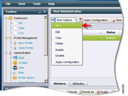
Access the Host Administration page from the Toolbox by clicking Administration > Host.
Configure Network Settings
Each computer configured to work with the Cisco MXE 3500 must belong to the same domain or workgroup as the ECS. The exact network specifications will differ depending on the existing network and administrator preference. For domain installations, network configuration will include creating IUSR and the Cisco MXE 3500 domain user accounts. For workgroup installations, network configuration will include verifying that identical, valid IUSR and the Cisco MXE 3500 user accounts have been created on each local Host.
The Cisco MXE 3500 runs the services, and the IUSR account is used to give the Web server access to other network resources.
Configure and Activate Host
When the Host is created, click on the Host to load its configured workers in the lower pane of the UI. From this pane, enable and configure workers for that Host. Then click the Apply Configuration button. See also: Creating a New Host.
Understanding Host Administration
Select a Host to display summary information about workers configured on that Host. Table 14-1 describes the fields.
Table 14-1 Host Administration Fields and Descriptions
Host
This is the name of the machine running the Cisco MXE 3500 LCS (Local Control System) and workers. The computer name and the Host name must match exactly.
To verify the computer name of a Windows Server computer, right-click the My Computer icon on either your desktop or in your Start Menu, select Properties, then select the Computer Name. For an NT computer, right-click Network Neighborhood, select Properties, and select the Identification tab. Alternately, type the hostname command at the command prompt to display the computer name.
Status
Displays the status of the Host: Enabled or Disabled.
To change the status, right-click the Host or click Host Options, and select Enabled or Disabled.
Note: If the status is disabled, jobs will not schedule on that Cisco MXE 3500 node.
Port
TCP (Transmission Control Protocol) port that the LCS is listening on (default is 3500).
Capacity
Reflects a numeric value (0-99) assigned for the total available processing capacity of the displayed Host.
Capacity can be any number for a given Host, but it is important that all Hosts be numbered according to the same standards. For example, for one particular Host it will not matter if the total capacity is set at 5 or at 10. However, if there is another Host that has twice the capacity, the capacity of both Hosts should be listed in common terms. So, a Host that is twice as powerful would have a capacity of 10 if the first Host was 5, or 20 if the first Host was 10.
Capacity is directly related to processor capacity, but may also be affected by drive speed, network congestion, and other factors. All of the factors that affect the amount of work a particular Host can do efficiently should be considered when assigning a capacity value.
Note
See also: Understanding Capacity, Limit, and Expense.
Temp Directory (UNC Name)
Specifies the directory where temporary files and preprocessor output will be stored. This must be entered as a UNC name so that other Hosts will be able to access files written to this directory. This is where preprocessor output and other temporary files will be written while the job is processing.
Unless the Preprocessor box in the Output Profile is checked to specify that Preprocessor files should be saved, files written to the Temp Directory will be deleted automatically when encoding is complete.
Permitted?
A green checkmark indicates that the worker listed to the right is configured to run on the displayed Host and that it is currently online and available to process tasks.
A red X indicates either:
•
•
Worker
Displays a list of all workers that have been configured to run on the displayed Host.
The Name, DV, DVCAM, Video Channel, and Audio Channel fields appear only for Live capture workers and define the location of the capture card on the Host. Channels are numbered sequentially from 0.
Licensed
Indicates the number of concurrent instances of this worker type (example: prefilter, encoder, distribution) that can be running on the system (all nodes controlled by that ECS). This value is defined in the Cisco MXE 3500 license file.
Limit
See the "Understanding Capacity, Limit, and Expense" section.
Expense
See the "Understanding Capacity, Limit, and Expense" section.
Capture Name
Defines the name associated with a live capture worker. Because Hosts can have more than a single video capture card and can be configured to run more than one Live capture worker, the Capture Name is required in order to identify the specific capture card used by the worker. This is only displayed for Live capture workers.
Capture Type
Type of capture card (DV, DVCAM, AJA-SDI, Custom, etc.). Selection of a non-custom value will predefine the audio and video channel
Video CH / Audio CH
Displays Video Channel and Audio Channel for each Live-capture worker.
Creating a New Host
When creating a Host, administrators must use the Windows Computer Account name (NetBIOS name) in order to create a Host that will be recognizable to the ECS.
See also: Creating a New Host Using the Right-Click Copy Option.
Procedure
Step 1
Step 2
Figure 14-1 Creating a New Host
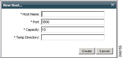
Figure 14-2 shows the pop-up that displays:
Figure 14-2 New Host Pop-up
Step 3
Step 4
Note
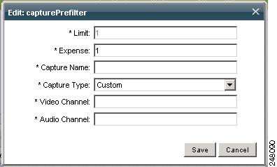
Step 5
Figure 14-3 Edit Worker
Step 6
Step 7
Step 8
Note
Creating a New Host Using the Right-Click Copy Option
Follow the same steps as noted above, but select a Host, and click Copy. This creates a new Host with the same worker configuration, except that the Captureprefilter worker settings are not copied to the new Host.
Enabling/Disabling a Host
After a Host is created, click on the Host to load its configured workers in the lower pane of the User Interface. From this pane, enable and configure workers for that Host. Then, click the Apply Configuration button. See also: Creating a New Host.
Procedure
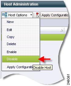
Step 1
Step 2
Figure 14-4 Disabling a Host
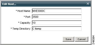
Editing Host Settings
Procedure
Step 1
Figure 14-5 Edit Host Pop-up
Step 2
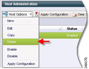
Deleting a Host
Procedure
Step 1
Step 2
Step 3
Figure 14-6 Deleting a Host
Adding Workers to a Host
Procedure
Step 1
Step 2
Step 3
Figure 14-7 Edit Pop-up
Step 4
Note
Step 5
Table 14-2 Worker Fields and Descriptions
Limit
Displays the maximum number of workers that can be run simultaneously on the displayed Host (0-99).
Limits can only be modified on the Host page by Resource Manager level licensees.
See also: Understanding Capacity, Limit, and Expense.
Expense
Note: Expense will be different for different types of workers. For example, MPEG encoding is more labor-intensive than Microsoft encoding. So, an MPEG worker is given a higher expense than a Microsoft worker.
Expense can only be modified on the Host page by Resource Manager level licensees.
See also: Understanding Capacity, Limit, and Expense.
Understanding Capacity, Limit, and Expense
The ECS uses capacity and expense to assign tasks to specific workers on specific Hosts in order to keep jobs moving through the encoding process in the most efficient way possible. The ECS uses Capacity and Expense to ensure that no single Host is over-burdened in order to prevent bottlenecks.
The processing power required by a particular type of worker may not always be the same. Limit is used with Capacity and Expense to accommodate this. For example, running one of a particular worker takes a certain amount, and running two may require double that amount. However, when a certain number is exceeded, the efficiency may degrade: Everything is fine until the fourth instance of the same worker is triggered. After this, the Host bogs down and performance suffers. Setting the Limit for this particular worker to three will prevent the ECS from triggering the fourth worker, even if there is sufficient capacity to accommodate the normal expense of the fourth instance. Because the expense would dramatically increase if the fourth worker were triggered, setting the Limit to three creates a threshold for the normal expense of a worker. Limit allows the administrator to set an upper limit on the number of instances that can run at the same time.
Removing Workers from a Host
Procedure
Step 1
Step 2
Step 3
Configuring Node Attributes
This section includes the following topics:
•
Node Attributes Overview
Node Attributes allow you to schedule specific job tasks or all tasks within a job against a set of Cisco MXE 3500 nodes that support those tasks.
Note
The node attribute feature has two purposes:
1.
2.
Tasks Matching Multiple Node Attributes
If a task (or job) matches multiple Node Attributes it will only be scheduled on a node that supports all matching attributes.
Scheduling Errors
If a task requires a specific Node Attribute that has not been assigned to any node, the task and job will fail with the following message:
[ECS_MISSINGNODEATTRIBUTE] A task (type: microsoft, id: 175) requested non-existent node
attribute. [EC_COMPLETED] Task Execution 175 is now complete. Reason = Failed.
Configuration Examples
Table 14-3 shows examples of how to configure the XPath and Apply To Job parameters of a Node Attribute to target specific nodes.
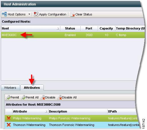
Assigning Node Attributes to a Host
The Attributes tab of the Host Administration page is used to assign one or more Node Attributes to a specific Host (node). Once a Node Attribute has been created, it is listed on the Attributes tab. It is then permitted (assigned) or disabled.
Procedure
Step 1
Step 2
Figure 14-8 Assigning Node Attribute to a Host
Step 3
Step 4
System Administration
This section includes the following topics:
•
•
•
•
•
•
Introduction to System Administration
System Administration is used to define locations and parameters for files and directories used with the Cisco MXE 3500. It also includes settings for other system-wide parameters.
Access this page from the Toolbox by clicking Administration > System.
The System Administration page contains the following sections:
•
•
•
•
•
•
•
•
Input (System Administration)
Figure 14-9 shows Input settings. Table 14-4 describes the settings.
Figure 14-9 Input Settings
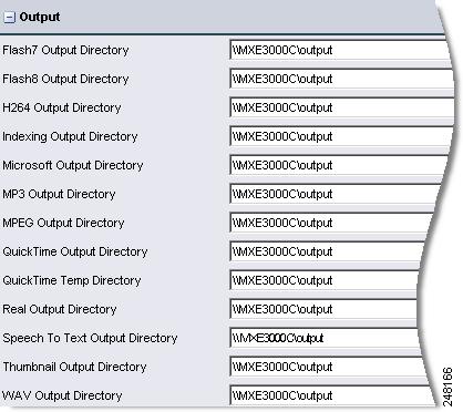
Output (System Administration)
Figure 14-10 shows Output settings.
Figure 14-10 Output Settings
Output Directories
Output Directories define the location the Cisco MXE 3500 will use to save files of each encoding format supported by the licensing levels of your Cisco MXE 3500 system. Encoded files will be saved to the defined directories when either no Distribution > Output Profile is included in the Job Profile or when the checkbox in the Save Local File section of the Output Profile has been checked.
The Microsoft Output Directory value can be entered either as a UNC path to a network share or to a mapped drive in the case of a deployment using a storage area network (SAN) or a single node deployment.
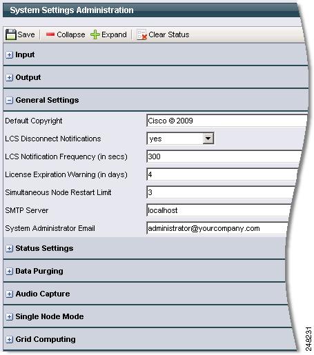
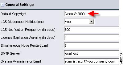
General Settings (System Administration)
Figure 14-11 shows General settings. Table 14-5 describes the settings.
Figure 14-11 General Settings
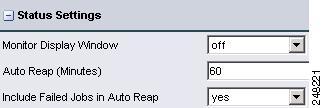
Status Settings (System Administration)
Figure 14-12 shows Status settings. Table 14-6 describes the settings.
Figure 14-12 Status Settings
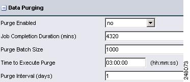
Data Purging (System Administration)
Over time, Job data (job, task, executioncontext, executioncontextlog, and related tables) grow and fill up disk space. The Data Purging section allows you to configure automated system purging, physically deleting the appropriate records.
Note
Figure 14-13 shows Data Purging settings. Table 14-7 describes the settings.
Figure 14-13 Data Purging Settings
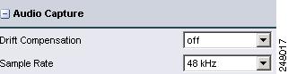
Audio Capture (System Administration)
Figure 14-14 shows Audio Capture settings. Table 14-8 describes the settings.
Figure 14-14 Audio Capture Settings
Table 14-8 Audio Capture Settings and Descriptions
Sample Rate
Sets audio sampling rate to tradeoff audio quality and transmission bandwidth and file size limitations.
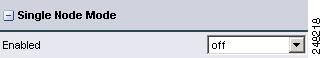
Single Node Mode (System Administration)
Figure 14-15 show Single Node Mode settings.
Figure 14-15 Single Node Mode Settings
Single Node Mode Settings
For users in bandwidth-sensitive environments, such as educational institutions and corporations, Single Node Mode provides greater control and the ability to confine encoding for a job to a single node.
Enabled: Enabling Single Node Mode forces all processing of a job to a single encoder node. The preprocessing, encoding, and distribution all takes place on one node rather then distributing the tasks across the system. This effectively reduces the amount of network traffic between the system nodes.
Disabled: Disabling Single Node Mode causes the system to distribute tasks to all the available nodes within a system. So, the preprocessing can occur on one node, the encode on another, and distribution on another. The Disabled setting allows more of the load balancing capabilities of the system. However, because the files are being moved through the workflow over multiple nodes, there will be more network traffic between the nodes within the system.
Soft node values Timeout/Queue Length have no range limit. The values need to be positive integers. The defaults are 3600 seconds (timeout) and 25 (queue limit).
The Timeout can be as large as you want. The value should be set relative to the average or maximum job length. You may want the tasks to flow to another node if the wait is going to be longer than the processing time and nodes are available.
Jobs are composed of Tasks. Tasks are the actual processes (preprocessing, encoding, and distribution) that together, make up a Job.
The Queue Length is set to a value that allows tasks to move to nodes that have a smaller queue. This value should be set relative to the average peak queue length the customer experiences. If the value is less than what normally occurs, performance will decrease.
These values are set to prevent individual nodes from getting backed up with Tasks. Single Node Mode can greatly improve performance for customers that do not have a network file storage system or do not have the network capacity to handle uncompressed AVI files. But, if individual nodes get backed up with more work, then performance is increased by letting the Tasks move to available nodes.
For customers with jobs/content that vary greatly in length or processing time, the system does not evaluate the input file or profile settings when distributing the tasks. For example:
20 jobs are submitted to a four-node system. Each fourth job is a full content encode that is 2 hours in length and will take an hour to process. The first three are a bumper, trailer, and preview encode that will be 15 to 30 seconds in length and take 5 - 15 seconds to run. If all are submitted sequentially in less than 5 seconds, the nodes will receive this distribution:
•
•
•
•
In this case, the user would want the 3 jobs that are pending on node 4 to flow to the 3 empty (2 minutes after submission) nodes. Setting the timeout to 5-30 minutes would save 2 1/2 - 3 hours of processing time in this case.
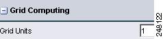
Grid Computing (System Administration)
Figure 14-16 shows Grid Computing settings. Grid Nodes: Enter the number of nodes that will be included in the grid. See also: Flash Grid.
Figure 14-16 Grid Computing Settings
Setting Default Copyright Information
This setting defines the default copyright information populated to the copyright field in all job submission pages. The Default Copyright is a system-wide setting. The value entered can be overwritten by the user when jobs are submitted by typing over the default information displayed.
Procedure
Step 1
Step 2
Figure 14-17 Default Copyright Field
Step 3
Configuring Output File Storage Location
Note
Procedure
Step 1
Step 2
•
•
Step 3
Enabling Sys Admin E-mail Notification
Procedure
Step 1
Step 2
Step 3
Step 4
Step 5
Turning Monitor Display Windows On/Off
This setting only applies in Console mode. If set to on, some workers (like preprocessor and encoders) will display a monitor window which displays the video being processed.
Note
Procedure
Step 1
Step 2
Step 3
Setting the Auto Reap Interval for Job Monitoring
The Auto Reap interval is used to clear job information from monitoring pages. The time defined for the Auto Reap determines how long information on a job will be displayed in monitoring pages before it expires. The Auto Reap interval is counted from the time the job completes.
Procedure
Step 1
Step 2
Step 3
User Administration
Activation
This section includes the following topics:
•
Introduction to User Administration
The User Administration page is used by administrators to set user access and permissions.
Access this page from the Toolbox by clicking Administration > User.
The top pane of User Administration displays users that have been created. The lower pane displays the permissions for each user.
The Cisco MXE 3500 comes with one predefined user:
•
Note
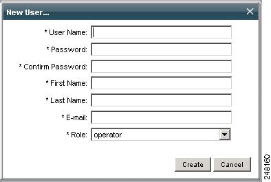
Creating New Users
Each person using the Cisco MXE 3500 needs a user profile that controls their system access.
Procedure
Step 1
Step 2
Figure 14-18 New User Pop-Up
Step 3
Step 4
Step 5
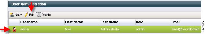
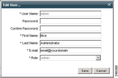
Updating Existing Users
Procedure
Step 1
Step 2
Figure 14-19 Select the User to be Edited
Figure 14-20 Edit User Pop-Up
Step 3
Step 4
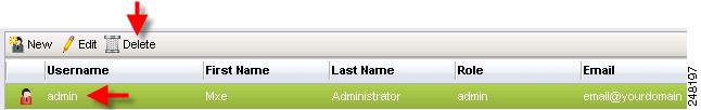
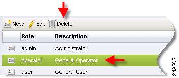
Deleting Users
Procedure
Step 1
Step 2
Figure 14-21 Select User to be Deleted
Step 3
Setting User Permissions
After creating a user, the System Administrator sets permissions for that user. Each user is allowed or denied permission to use the following Cisco MXE 3500 features:
•
•
•
•
•
•
•
•
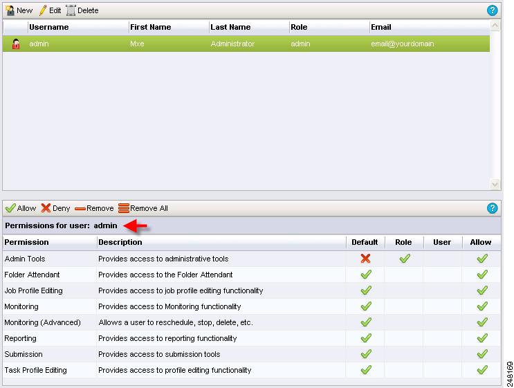
The permissions for a selected user are displayed at the bottom of the page. See Figure 14-22.
Figure 14-22 Permissions for the Selected User
Four columns display the permissions that have been set for this user. Table 14-10 describes the settings.
The red X indicates that permissions for that feature are denied, and the green check mark indicates that the selected user has permissions to access the feature.
Read the permission table from left to right: marks in the column to the right override the previous column.
The Default permissions are shown in the first column. These are default permissions that come loaded in the system.
The Role column shows the permissions for the Role assigned to this user. The permissions for the Role override the default permissions and are set on the Role Administration page.
The User permissions show the permissions for this specific user. These permissions override both the Default and Role permissions for this user only. Modify the permissions for the selected user shown in this column by following the procedure described below.
To quickly determine if certain permissions are allowed for a user, view the Allow column.
The picture above is an example of permissions set for the user named JSmith who has been assigned the user role. Notice that by default, those in the user role do not have access to Admin Tools (in this case) but have access to the remaining features. However, an administrator has added (overridden) the Admin Tools permission to this user's role.
For each feature, you can specify whether or not to allow, deny, or remove the user's access. You can also choose to remove all access to all features for a specific user.
Procedure
Step 1
Step 2
Step 3
•
•
•
•
•
•
•
•
Step 4
Step 5
Role Administration
Activation
This section includes the following topics:
•
Introduction to Role Administration
Each Cisco MXE 3500 user is assigned a role that controls their level of access to the various system features.
Access this page from the Toolbox by clicking Administration > Role.
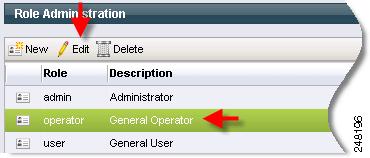
The top pane of the Role Administration page displays roles that have been created. The lower pane displays the permissions for each role.
The Cisco MXE 3500 comes with three predefined roles:
•
•
•
•
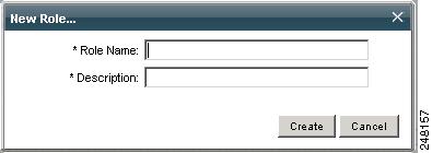
Creating Roles
Use this procedure to create a new role.
Procedure
Step 1
Step 2
Figure 14-23 New Role Pop-up
Step 3
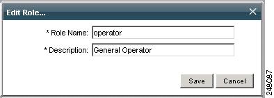
Updating Roles
Use this procedure to update an existing role.
Procedure
Step 1
Step 2
Figure 14-24 Select Role to Edit
Step 3
Figure 14-25 Edit Role Pop-up
Step 4
Step 5
Setting Role Permissions
After creating a role, the System Administrator sets permissions for that role. Each role is allowed or denied permission to use the following Cisco MXE 3500 features:
•
•
•
•
•
•
•
•
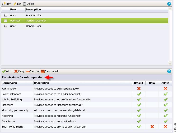
The permissions for a selected role are displayed at the bottom of the page. See Figure 14-26.
Figure 14-26 Permissions for the Selected Role
Three columns display the permissions that have been set for each role. Table 14-12 describes the permissions.
The red X indicates that permission for that feature are denied, and the green check mark indicates that the user in this role has permission to access the feature.
Read the permission table from left to right: marks in the column to the right override the previous column.
In the example above, the monitor role came loaded (by default) with access to Folder Attendant, Monitoring, and Submission features. In this case, an administrator has removed, for the role called monitor, access to Folder Attendant and Submission features. The monitor role now allows access to Monitoring functions only.
Modify the permissions for the selected role by following the procedure below.
For each feature, you can specify whether or not to allow, deny, or remove access. You can also choose to remove all access to all features for a specific role.
Procedure
Step 1
Step 2
Step 3
•
•
•
•
•
•
•
•
Step 4
Step 5
Deleting Roles
You can only delete a role if it contains no users. If the role contains users and you try to delete it, the following message displays:
"The current role contains users and cannot be deleted."
Procedure
Step 1
Step 2
Figure 14-27 Select the Role to be Deleted
Step 3
Step 4
Profile Spaces
Activation
The Profile Spaces feature allows you to manage multiple profile directories within the system. The Cisco MXE 3500 is shipped with a single profile directory. The initial database setting for profiledir is:
C:\Program Files\Cisco\Media Experience Engine\profiles
The Cisco MXE 3500 uses the system setting-configured profile directory to access the list of Job Profiles. However, you may want to maintain separate profile directories for separate groups or for separate customers.
You can create as many Profile Spaces as you need, but the Cisco MXE 3500 will check to see that each profile directory exists at the time of creation.
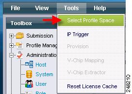
Your Cisco MXE 3500 session links to one Profile Space at a time, thereby determining the profiles that you can view from the Profile Browser. You can change your working Profile Space at any time by clicking Tools > Select Profile Space. See Figure 14-28.
Figure 14-28 Profile Space Administration
This section includes the following topics:
•
•
Determining Your Current Profile Space
Your current Profile Space is displayed in the upper right corner of the Web browser. See Figure 14-29.
Figure 14-29 Current Profile Space
Setting Your Current Profile Space
Your Cisco MXE 3500 session links to one Profile Space at a time, thereby determining the profiles that you can view from the Profile Browser. You can change your working Profile Space at any time.
Procedure
Step 1
Figure 14-30 Selecting Profile Space
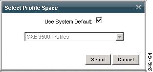
Step 2
Note
Figure 14-31 Selecting a Profile Space
Creating a Profile Space
Procedure
Step 1
Step 2
Figure 14-32 Creating New Profile Space
Step 3
Figure 14-33 Entering Name and Directory
Editing a Profile Space
The editing of Profile Spaces is disallowed in Release 3.1 and later.
Deleting a Profile Space
Procedure
Step 1
Step 2
Figure 14-34 Selecting a Profile Space to Delete
Step 3
User Metadata
Activation
This section allows you to create custom name/value pairs that can be submitted with each job (and each task in the job). This custom metadata is returned in detailed job status including the HTTP POST job-status XML. This metadata (if submitted) is also stored in the database for each job and can be used for reporting purposes (like tracking which organization submitted which jobs) or (via HTTP POST) where it is passed back to other systems (like Velocity).
The Data Type can be defined as Integer, String, Decimal, or Enum (Enumeration). This type is used for validation when entering the user metadata values on the Job Submission pages.
Access this page from the Toolbox by clicking Administration > User Metadata.
This section includes the following topics:
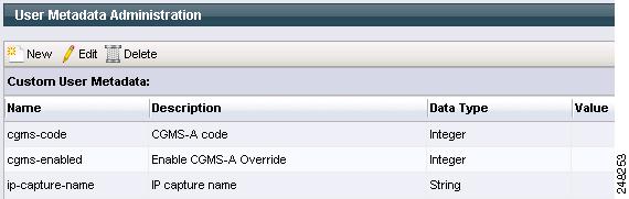
Adding User Metadata
Use this procedure to add a custom name/value pair.
Procedure
Step 1
Figure 14-35 User Metadata Administration Page
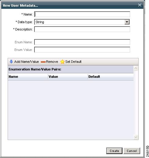
Step 2
Figure 14-36 New User Metadata Pop-up
Step 3
Editing User Metadata
Procedure
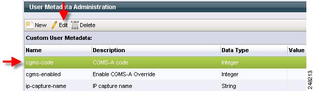
Step 1
Figure 14-37 Selecting User Metadata to Edit
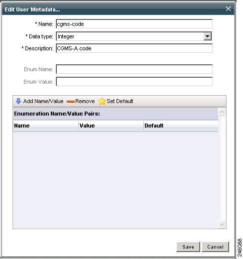
Step 2
Figure 14-38 Edit User Metadata Pop-up
Step 3
Deleting User Metadata
Procedure
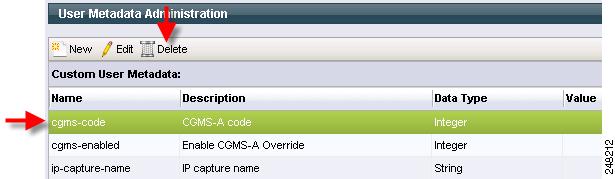
Step 1
Figure 14-39 User Metadata Administration Page
Step 2
Step 3
IP Capture (Live Streaming)
Activation
This section includes the following topics:
•
•
•
•
IP Capture Overview (Live Streaming)
The Cisco MXE 3500 enables ingest of live MPEG-2 and Windows media transport streams over UDP/IP with management, configuration, and status that enable general use of this feature. IP captures are limited to transport streams with MPEG-2 video and AC3/Layer2/AES3 audio essences.
Before submitting a job, you must configure the ipCapturePrefilter Worker on the Host Administration page. See also: Adding Workers to a Host.
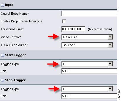
In addition, on the Live Submission page, you set the Video Format to IP Capture and select the IP Capture Source (as defined in Adding an IP Capture Source (Live Streaming)), and Start and Stop Trigger Types. See Figure 14-40.
Figure 14-40 Live Submission Page IP Capture Settings
You may send a start or stop trigger command to the running capture displayed in the Job Status Monitor (assuming start/stop IP triggers were configured with the Live Job Submission) by clicking on the Job, then Tools > IP Trigger.
If you are running concurrent IP captures with the same IP capture configuration along with IP triggers, you need to enter a unique ip-capture-name in the UDM field on the Live Submission page to uniquely identify the list of IP captures to send a trigger to.
On the Live Submission page, when you select the IP Capture video format, the IP Capture sources are automatically populated (from the names in the configuration page). For the selected IP Capture Source, the name will be automatically populated in the ip-capture-name UDM field. You may choose to manually override this UDM field.
Note
Adding an IP Capture Source (Live Streaming)
Procedure
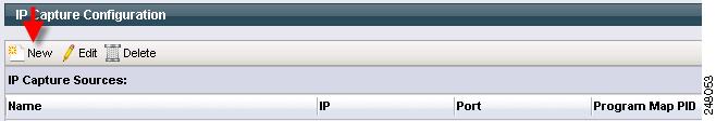
Step 1
Step 2
Figure 14-41 Creating New IP Capture Source
Step 3
Figure 14-42 New IP Capture Source Pop-up
Figure 14-43 Example UDP Source Configuration
Figure 14-44 Example Windows Media Source Configuration
Editing an IP Capture Source (Live Streaming)
Procedure
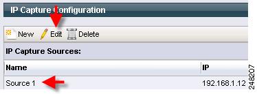
Step 1
Step 2
Figure 14-45 Selecting IP Capture Source to Edit
Step 3
Figure 14-46 Edit IP Capture Source Pop-up
Deleting an IP Capture Source (Live Streaming)
Procedure
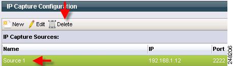
Step 1
Step 2
Figure 14-47 Selecting IP Capture Source to Delete
Step 3
Video Conversion Interface (SUI)
The Cisco MXE 3500 provides an easy to use Video Conversion Interface that is oriented for end users who want to convert between video formats while providing minimal details. End users access the Video Conversion Interface at http://mxe_IP_address/sui.
To use the interface, the user simply points to a video on a local drive, uploads it, and provides a title and description. The user can then request converted output in various file formats with the addition of bumpers, trailers, overlays, and watermarks. No choice of these assets is possible; all are preconfigured through the SUI Administration page.
Access the SUI administration page from the Toolbox by clicking Administration > SUI Admin.
Figure 14-48 SUI Administration Page
Figure 14-49 shows the General Settings section. Table 14-15 describes the settings.
Figure 14-49 General Settings Section
Figure 14-50 shows the Media File Assets section. Table 14-16 describes the settings.
Figure 14-50 Media File Assets Settings
Figure 14-51 shows the Show and Share section. Table 14-17 describes the settings.
Figure 14-51 Cisco Show and Share Settings
Figure 14-52 shows the Stream Server section. Table 14-18 describes the settings.
Figure 14-52 Stream Server Settings
For instructions on how to use the Video Conversion Interface see Using the Cisco MXE 3500 Release 3.3 Video Conversion Interface on Cisco.com.
API Administration
There are two components of API administration, both affecting behavior of the Cisco MXE REST API: authentication mode and authentication password.
•
•
Configuring Authentication Mode
Note
Procedure
Step 1
Step 2
Figure 14-53 API Admin Page
Step 3
Step 4
Step 5
Changing the Authentication Password
Note
Procedure
Step 1
Step 2
Step 3
Step 4
Step 5
LDAP Settings
Use the LDAP Settings page to configure LDAP settings. If LDAP is enabled, SUI user authentication is done with LDAP.
Before You Begin
•
(1) maps to an attribute that is not composite name and (2) does not require a password change at first log in. Note that the Video Conversion Interface (SUI) requires a single word—not a composite as a user ID —for authentication.•
Procedure
Step 1
Figure 14-54 Access LDAP Settings
Step 2
Figure 14-55 LDAP Settings Page
Step 3
Note
Step 4
Shared Folder Access Settings
Use this feature to configure access to shared folders. This sections contains the following topics:
•
•
Shared Folder Access Settings Page
From the Toolbox, expand Administration, and click Shared Folder Access Settings. Figure 14-56 shows the Shared Folder Access Settings page.
Figure 14-56 Shared Folder Access Settings Page
Table 14-20 describes the Active Directory fields.
Configuring Access to Shared Folders
Configure access to the shared folders in one of the following modes:
Open Access Mode
The open access mode is the default mode for accessing the MXE 3500 shared folders. In this mode, users do not need a username and password to access the shared folders.
To enable this mode, uncheck the Secure option in the Enable Secure Access section of the Shared Folder Access Settings page.
Active Directory Mode
•
About Active Directory Mode
The Active Directory (AD) mode allows users access to the Cisco MXE 3500 shared folders with their Enterprise domain login credentials.
Integrating with AD eliminates the need to maintain users and their account details on the Cisco MXE 3500 appliance. Users can access the following using their Enterprise login credentials:
•
•
Note
Note
Before You Begin
•
•
The applications on the Cisco MXE 3500 run as a service. These services are associated with the preconfigured mxe-service user . When AD is implemented, the user associated with the Cisco MXE 3500 services must be changed to a user configured in the AD system.
Enable Active Directory Mode
To enable AD, do the following in the Shared Folder Access Settings page:
Step 1
Step 2
Step 3
Tip
Step 4
Step 5
Step 6
The AddServiceUser.bat script creates the new user on the Windows platform. It then associates all Cisco MXE 3500 services to the new user.
Step 7
a.
b.
c.
d.
Disable Active Directory Mode
To disable AD, do the following in the Shared Folder Access Settings page:
Step 1
Step 2
Step 3
Step 4
Step 5
a.
b.
c.
d.
Local User Access Mode
The local user access mode allows users access to the MXE 3500 shared folders with a single username and password combination that is set to mxe-user. Users are provided the option to update the password for the shared folder account.
Enterprises that do not have an AD or choose not to tie the system with the AD use this mode to secure access to the shared folders.
To enable local user access mode, do the following in the Shared Folder Access Settings page:
Step 1
Step 2
Step 3
Step 4
Additional Administrative Tools
In addition to the administrative tools available on the main the Web User Interface (UI), the Cisco MXE 3500 offers additional features:
•
•
•
•
Cisco MXE 3500 Tools
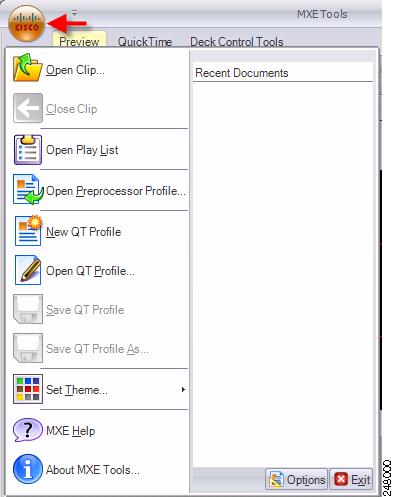
To access Cisco MXE 3500 Tools, click on the Cisco desktop icon or click Start > All Programs > Cisco > Media Experience Engine > Media Experience Engine Tools.
Note
Click the Cisco icon in the upper left corner to view the Cisco MXE 3500 Tools menu. See Figure 14-57.
Figure 14-57 Accessing Cisco MXE 3500 Tools Options
See also:
•
•
•
Setting Independent Profile Space
The Cisco MXE 3500 Tools application has the ability to set a profile space independently of the Cisco MXE 3500 UI profile space.
Procedure
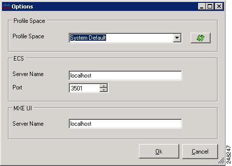
Step 1
Step 2
Step 3
Figure 14-58 Tools Options
Step 4
Note
Profile Converter
The purpose of the Cisco MXE 3500 Profile Converter is to update, through a Wizard, pre-existing profiles so that they are editable by someone using the Cisco MXE 3500 UI. The Profile Converter applies dependency rules and defaults that normalize the profiles and ensure that they will be acceptable to the current Profile Editor in the MXE 3500 UI.
In addition to making the profiles compatible with the Cisco MXE 3500, the Profile Converter sets proper defaults and corrects for settings that do not fall into the valid range of values. For example, a setting that is out of range may be corrected, or a tag may list a feature that does not exist in the profile definition.
Converted profiles should be evaluated and tested to verify that any changes made during the conversion produce the expected transcoding results in the Cisco MXE 3500. The Profile Converter produces an upgrade log that is written to the root of the selected profile directory before the wizard exits. The upgrade log is an HTML document that can be viewed with a browser. It displays changes and modifications made to each profile, as well as errors that may have occurred during processing.
Note
When the Profile Converter runs, it makes a back-up of any profile that it changes. The back-ups are located in the same directory as the profile that was updated with a .bak file extension.
Note
See also: Profile Converter Log Entries.
Running the Profile Converter
The Profile Converter scans one profile directory at a time and scans for files to upgrade to Cisco MXE 3500 profile standards. The converter is a wizard that runs in several stages:
Procedure
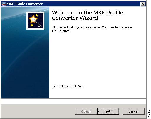
Step 1
Figure 14-59 Profile Converter Welcome Screen
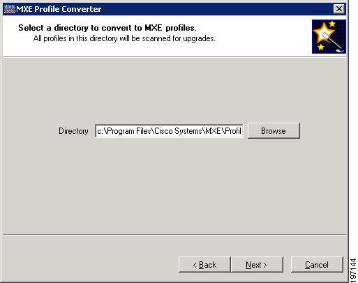
Step 2
Figure 14-60 Selecting the Profile Directory
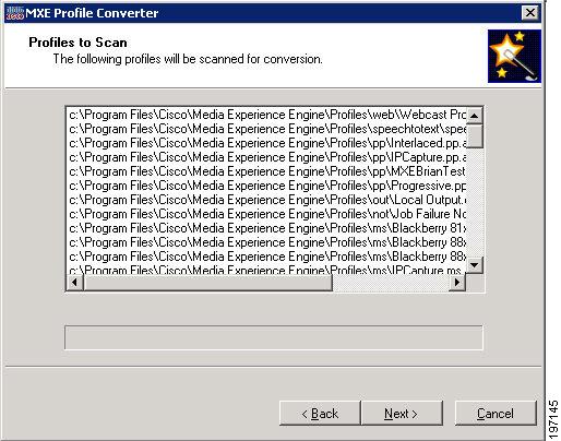
Step 3
Figure 14-61 Profiles to Scan List
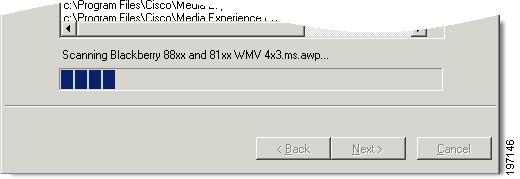
Step 4
Figure 14-62 Scan Progress Bar
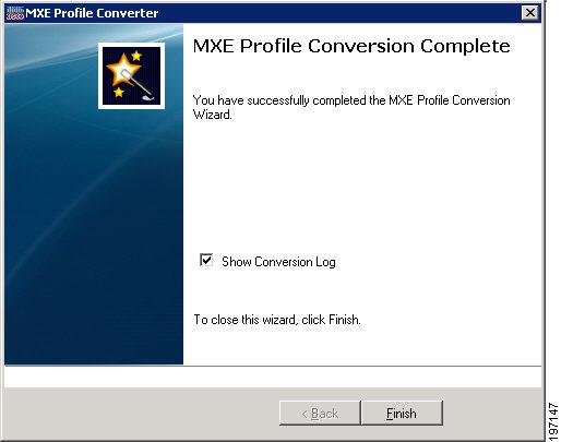
Step 5
Step 6
Figure 14-63 Profile Conversion Complete
Profile Converter Log Entries
When you run the Profile Converter, a conversion log is produced. The log contains two main types of log messages:
•
•
Table 14-21 describes the log entries.
Database Configuration
The Database Configuration Tool is normally used during the installation process to set up, configure, and migrate databases. However, it may also be used by administrators needing to update or maintain their database.
This tool offers a simple user interface that allows you to:
•
•
•
•
•
To access the Cisco MXE 3500 Database Configuration tool
•
Figure 14-64 Database Configuration Tool
Log Viewer
The Log Viewer is not supported in Release 3.2.