Feedback
Table Of Contents
Setting Up Prime Analytics Projects
Defining the Application and Database Streams
Managing Connectors and Handlers
Building a NetFlow Application
Troubleshooting Handlers and Connectors
Compiling the Prime Analytics Project
Starting and Monitoring the Project
Setting Up Prime Analytics Projects
After you install Prime Analytics, you must complete the following procedures to set up Prime Analytics projects. These include setup of handlers and connectors that link the data source to the CQ engine, and CQ engine output to the BI platform. Additionally, you must define queries to display the data in which you are interested.
Topics include:
•
Defining the Application and Database Streams
•
•
•
Creating the Project
Creating a project creates a dedicated project directory where all application elements are stored.
To create the Prime Analytics project:
Step 1
source /etc/sysconfig/primeanalytics/primeaexport JAVA_HOMEStep 2
TRUVISO_HOME is an environment variable defined in a script called /etc/sysconfig/primeanalytics/primea. The script contains other variables such as JAVA_HOME and PA_HOME. To build or run applications, you must define all environment variables correctly. The easiest way to define them is to run the script, $PA_HOME/bin/pa_env.sh, where PA_HOME is set by /etc/sysconfig/primeanalytics/primea. You must source $PA_HOME/bin/pa_env.sh to set environment variables.
Step 3
ls -l ~/projectsIf the projects directory is not present, create one:
mkdir ~/projectsStep 4
cd ~/projects$TRUVISO_HOME/Scripts/make-application.sh projectnamecd ~/projects/projectnamels -l
Note
Your project directory should now contain a customization directory. It contains files that you can edit, including:
•
•
•
•
Defining the Application and Database Streams
After you create your project, the next step is to define the continuous stream application and its database streams. To accomplish this, you edit the customizations/db/ddl.sql file.
To define the continuous stream application and its database streams:
•
ant run-ddlor
psql -U primea -a -f customizations/db/ddl.sqlVerify the DDL
Now you will verify the DDL.
To verify the DDL:
Step 1
psql -CStep 2
set search_path=my_schema,public;Step 3
\q
Managing Connectors and Handlers
Prime Analytics connectors and handlers connect to data sources and populate data streams. Connectors extract and transform the data and integrate it with the CQ engine. They also integrate CQ engine output with enterprise applications. Connectors provide the basic infrastructure to manage the CQ life cycle. To fine tune the data processing, handlers are provided to manage the small streaming data details including input, record parsing, and data flow management coming in and out of the CQ engine.
Connectors are deployed in the following directories:
•
•
To configure connectors and handlers:
Step 1
The data.xml file is the root configuration file for a Prime Analytics project. All customizations can be performed by editing this file. However, the best practice is to create a pointer to a separate file for maintenance and support cases.
Step 2
<!ENTITY connectors SYSTEM "include-connectors.xml">Step 3
&connectors;This entry allows you to configure all connectors and/or handlers in the include-connectors.xml file instead of the data.xml file. The include-connectors.xml file should be present in the same directory as the data.xml file.
Step 4
Step 5
•
•
Managing Handler Chains
Handlers manage the chain of events required to push data into the Prime Analytics CQ engine. The <producers> element contains a list of <chain> elements. Each element defines a single handler chain. Prime Analytics built-in data handlers are listed in Table 2-1.
Table 2-3 shows the handlers organized by function.
You can create parallel handler chains to optimize performance. Parallel chains can include built-in handlers and any custom handlers you create. To enable multi-threaded data processing, set the handler queue attribute to indicate the handler runs in parallel mode. Additional threads and queue size attributes allow you to fine tune the process. All down stream processing is performed in the threads initiated for this handler.
If you use multiplexing and full transactional semantics for publishing data to the continuous query engine, use the twophasepump handler instead of the regular pump handler to push the data. This ensures that all data is aborted or committed. The twophasepump handler uses the PostgreSQL prepared transactions feature. If you use the 'twophasepump, raise the max_prepared_transactions setting in postgresql.conf. The default is 5. This is sufficient for a typical installations, but is not sufficient if you use the twophasepump handler extensively. The recommended practice is to set this to the same value as max_connections.
If you use prepared transactions, monitor the pg_catalog.pg_prepared_xacts table periodically for stranded prepared transactions. For a full description of the prepared transaction feature, consult the PostgreSQL documentation.
Available parameters include:
queue—Enables the queue-based, multi-threaded capabilities for the current handler. The default is false
•
•
Defining the Handler
To enable the Prime Analytics BI platform to recognize handler, you must define it in either the include-connectors.xml or data.xml configuration file. Required configuration parameters to include in the <handler> xml definition include:
•
<file> <location>/path_to_file/file</location> </file>The location parameter is required by the handler in order to proceed. In this case, it requires the location of the file that needs to be processed.
•
<socket> <port>1234</port> </socket>THROTTLE—Modifies the incoming data rate. This handler is often used to simulate high peak traffic periods for performance testing. The parameters are:
–
–
–
–
<throttle> <cqtimedatepattern>yyy-MM-dd HH:mm:ss</cqtimedatepattern> <cqtimecolumnindex>1</cqtimecolumnindex> <pumpratio>10</pumpratio></thottle>•
<jms> <jmsBrokerId>broker1</jmsBrokerId> <jmsUri>jms:queue:ExampleQueueNamefitimeToLive=1000</jmsUri> <jmsContextFactory>org.apache.activemq.jndi.ActiveMQInitialContextFactory</jmsContextF actory> <jmsConnectionFactory>QueueConnectionFactory</jmsConnectionFactory> <jmsQueue>queue1</jmsQueue> <jmsUsername>jms_user</jmsQueue> <jmsPassword>jms_pwd</jmsPassword></jms>•
<commit> <rows>1000</rows> </commit>Although transaction size depends on your application requirements, as a general guideline, set commits to one per second for high data rates. For example, for a NetFlow with 50,000 flows (rows) per second, you would set commit to 50000 rows. You can set faster and slower commit rates. However, never set commit rates less than 100 per second to avoid problems caused by the volume of overhead operations for each commit.
Handler Chain Example
The following sample handler chain pulls data from a comma delimited sample_file.txt file. The file is a small representation of the actual source data. To simulate a production environment, the file is replayed and throttled to simulate large data volumes and fast data rates. The file and throttle handlers are used in this example. The file handler is extended to include replay capability as follows:
import com.truviso.system.handlers.* ;public class FileReplayHandler extends AbstractHandler<Connector, InputStream> { Filefile;private static final Logger LOGGER = Logger.getLogger(FileReplayHandler.class);private static final int DEFAULT_MAX_CACHE_SIZE = 5000;private ArrayList<Object> inputCacheList; private int iterations; private intmaxcachesize;private String location;public FileReplayHandler(SubnodeConfiguration c) throws HandlerException { super(c); }public void init() throws HandlerException { super.init();iterations = config.getInt("iterations"); maxcachesize = config.getInt("maxcachesize"); location = config.getString("location"); if (location == null)throw new HandlerException("Please specify location element for file handler");file = new File(location); if (!file.exists())throw new HandlerException(String.format("File %s does not exist", location));maxcachesize = maxcachesize<=0fiDEFAULT_MAX_CACHE_SIZE:maxcachesize; inputCacheList =new ArrayList<Object>();}public void handle(Connector producer) throws HandlerException {for (int i = 0; i < iterations && isRunning(); i++){ LOGGER.debug("============================================================================ =================" LOGGER.debug("iteration: " + i); LOGGER.debug("============================================================================ =================" try {InputStream in = new FileInputStream(file); resultListener.handle(in); } catch (FileNotFoundException e) { throw new HandlerException(String.format("Unable to read file %s", file.getAbsolutePath }} }}The following parameters are added:
•
•
<handlers> <chain id="FILE_REPLAY_THROTTLE"><custom class="com.truviso.system.handlers.FileReplayHandler"> <iterations>1000</iterations> <location>/tmp/source_file.txt</location> <maxcachesize>5000</maxcachesize></custom><inputstream/><text> <delimiter>,</delimiter></text><custom class="com.truviso.system.handlers.ThrottleHandler"> <cqtimedatepattern>yyyy-MM-dd HH:mm:ss</cqtimedatepattern> <cqtimecolumnindex>1</cqtimecolumnindex> <pumpratio>100</pumpratio> <keeporiginalcqtime>false</keeporiginalcqtime></custom><pump> <type>COPY</type> <mode>CSV</mode> <schema>my_schema</schema> <stream>my_stream</stream></pump> </chain> </handlers>The handler chain is configured as follows:
•
•
•
•
•
Building a NetFlow Application
NetFlow is a Cisco IOS embedded instrumentation that characterizes network operations. Each packet forwarded within a router or switch is examined for a set of IP packet attributes. These attributes are the IP packet identity or fingerprint. They determine if the packet is unique or similar to other packets. An IP NetFlow is usually based on a set of five and up to seven IP packet attributes:
•
•
•
•
•
•
•
All packets with the same source and destination IP address and ports, protocol interface, and class of service are grouped into a flow. The packets and bytes are then tallied. The router or switch sends these tallied flows to a collector to process the data.
The Prime Analytics NetFlow handler receives this information, parses it and feeds it to the CQ engine (TruCQ) for analysis. A handler chain, defined in the file customizations/templates/include-
handlers.xml, specifies the input processing path. Here is a sample NetFlow processing chain:<handlers><chain id="netflow"><udpnetflow><port>2055</port><rcvbufsize>16000000</rcvbufsize></udpnetflow><netflow queue="true" threads="8"><fields>UTCtime,routerIP,sequence,input-key,srcaddr-key,srcport-key,output-key,dstaddr-key ,dstport-key,in-packets-key,in-bytes-key</fields></netflow><commitbytes><rows>50000</rows></commitbytes><pumpbytes><type>COPY</type><mode>BYTES</mode><autoflush>false</autoflush><schema>netflow</schema><stream>netflow</stream></pumpbytes></chain></handlers>The first handler entry, udpnetflow, indicates the incoming port number and a receive buffer size. NetFlow typically arrives at a high data rate. A large receive buffer prevents packet loss (the UDP protocol does not retransmit dropped packets). The Linux kernel imposes a limit on receive buffer size. The system administrator (root) must increase the limit using a command. For example,
sysctl net.core.rmem_max=16000000The next entry, netflow, indicates the fields to be extracted from the received data and sent as columns to the streaming engine. The commitbytes and pumpbytes entries correspond to the <commit> and <pump> entries used with other handlers, but they process binary data instead of strings. The <netflow> handler emits its results in an internal binary form to reduce overhead.
The file customizations/db/ddl.sql specifies an input schema for stream processing. Here is an example that matches the above handler chain:
CREATE STREAM netflow (tod timestamp with time zone cqtime user drift '1 second',routerip text,sequence bigint,inputif bigint,srcaddr text,srcport bigint,outputif bigint,destaddr text,destport bigint,packets bigint,bytes bigint) checkpoint ;Note the use of bigint for numeric columns. This is required. NetFlow packets include a time of day specified in UTC. The timestamp with time zone adjusts correctly for UTC times.
Note
Table 2-4 shows the NetFlow field IDs
Building a Syslog Application
Syslog is the standard for logging system events. It separates the applications that generate messages from the system that stores them and the applications that report and analyze them. Syslog protocol is defined by the Internet Engineering Task Force (IETF). The protocol is extendable and the log messages format is customized.
The Prime Analytics syslog handler (SyslogHandler) parses the log messages. The logs have fixed formats including fixed delimiter and timestamp fields. The SyslogHandler receives log messages, parses them, them feeds the messages to the Prime Analytics CQ engine (TruCQ) for analysis.
When creating an application with syslog handler chain, keep the following points in mind:
•
•
•
•
–
–
–
•
•
Some syslog message examples:
<166>Jul 5 2013 02:47:22 172.20.35.150/Admin %ACE-6-302022: Built TCP connection
0x289111 for vlan28:172.20.35.177/33671 (172.20.35.177/33671) to
vlan28:172.20.35.135/443 (172.20.35.135/443)
To build an application based on the SyslogHandler;
Step 1
CREATE STREAM syslog(source inet, -- Source IPqtime timestamp cqtime user, -- Syslog timestamppriority varhcar, -- priority defined in Syslogmsgs varchar -- Syslog messages content) checkpoint;Step 2
The Prime Analytics TruLink component handles input processing. A handler chain, defined in the file customizations/templates/include-handlers.xml, specifies the input processing path. Here is a process syslog example receiving UDP packets:
<handlers><chain id="syslog_udp"><udpsyslog><port>514</port></udpsyslog><sylsog><location>definition.xml</location></syslog><commit><rows>50000</rows></commit><pump><type>COPY</type><mode>CSV</mode><schema>syslog</schema><stream>syslog_base</stream></pump></chain></handlers>The first handler entry, udpsyslog, indicates the incoming port number and a receive buffer size(optional). Most syslog protocol uses UDP as transport protocol. However, UDP protocol provides no guarantees for message delivery. If the message rate is high, some packets might be lost. A large receive buffer prevents packet loss. The Linux kernel imposes a limit on receive buffer size. The system administrator (root) must increase the limit through a command, for example:
sysctl net.core.rmem_max=16000000The next entry, syslog, identifies the definition files that tell how the received data is extracted and sent as columns to the streaming engine. Multiple definition files are supported. These are divided by commas, for example, <location>def1.xml, def2.xml</location>.
SyslogHandler can also read log files from local files, for example:
<handlers><chain id="syslog_file"><file><location>${syslog.log}</location></file><inputstream/><packetwrapper/><sylsog><location>definition.xml</location></syslog><commit><rows>50000</rows></commit><pump><type>COPY</type><mode>CSV</mode><schema>syslog</schema><stream>syslog_base</stream></pump></chain></handlers>The first handler entry, file, reads data streams from the syslog.log, which is defined in local-runtime.properties. The inputstream handler converts input streams into lines. The packetwrapper is a wrapper handler which adapts the syslog line and syslog handler.
Step 3
The parser definition file is required in the Prime Analytics project. It specifies how to parse the message, and how to generate columns. Here is an example:
<?xml version="1.0" encoding="ISO-8859-1"?><!DOCTYPE parser SYSTEM "customizations/templates/handlers/syslogparser.dtd"><parser><attribute><delimiter>" "</delimiter><identifier><![CDATA[*]]></identifier></attribute><token id="token1"><index>0</index></token><token id="token2"><index>1</index></token><token id="token3"><index>2</index><regex>regex</regex></token><token id="token4"><index>4</index><kvdelimiter>=</kvdelimiter></token><column><name>column1</name><index>1</index><value>token.token1.1</value></column><column><name>column2</name><index>2</index><value>token.token2.1+" "+token.token3.1</value></column><column><name>column3</name><index>3</index><value>token.token3.1</value><dateformat>MM dd HH:mm:SS.SSS Z</dateformat></column><column><name>column4</name><index>4</index><value>token.token4.n</value><map>key1=value1,key2=value2</map></column><column><name>column5</name><index>5</index><value>token.token4.n</value><hstore>true</hstore></column><column><name>column6</name><index>6</index><value></value></column><column><name>column7</name><index>7</index><value>packet.source.ip</value></column><column><name>column8</name><index>8</index><value>packet.source.port</value></column></parser>SyslogHandler Definition File Syntax
•
<?xml version="1.0" encoding="ISO-8859-1"?><!DOCTYPE parser SYSTEM "customized/templates/handlers/syslogparser.dtd"><parser><attribute><delimiter>" "</delimiter><identifier><![CDATA[*]]></identifier></attribute><token></token><column></column></parser>All definition file contains three basic elements: attribute, token and column. The attribute contains two sub elements: delimiter and identifier. The delimiter divides the raw syslog messages into tokens. It could be one character, one word or a symbol. The double quotas around the delimiter is optional. The identifier filters the incoming syslog and maps the matched message to the corresponding parser, which is defined in different definition files. Two definition files must be defined for each syslog with unique identifiers. The wildcard means ignore the filters. If multiple definition files are defined, syslog messages are filtered sequentially. The first matched definition file is applied. For example:
<identifier><![CDATA[warning]]></identifier>.In this example, any message containing the word, warning, is filtered and parsed by the current definition file.
•
–
–
–
In the following example, the delimiter is a whitespace and syslog message is:
<166>Jul 5 2013 02:47:22 172.20.35.150/Admin %ACE-6-302022: Built TCP connection 0x289111 for vlan28:172.20.35.177/33671 (172.20.35.177/33671) to vlan28:172.20.35.135/443 (172.20.35.135/443)<token id="PRIORITY"><index>1</index> <!-- it refers to "<166>Jul" --><regex><(\d)></regex> <!-- the regex expression extracts from above token value, the result is 166 --></token><token id="LEVEL"><index>6</index> <!-- it refers to "%ACE-6-302022:" --><regex>%ACE-(\d+)-\d+</regex> <!-- the result is "6" --></token>2013/02/22 09:00:00.019 SdvSmTxSelConf,STB=10.250.82.233,TID=0xef3,SesId=001bd74bbd44/0,RC=OK,MPN=1092,Freq=68 1000000,Mod=16,Tsid=48691,SGID=1309<token id="detail"><index>3</index> <!-- it refers to "SdvSmTxSelConf,STB=10.250.82.233,TID=0xef3,SesId=001bd74bbd44/0,RC=OK,MPN=1092,Freq=6 81000000,Mod=16,Tsid=48691,SGID=1309" --><kvdelimiter>=</kvdelimiter> <!-- the result is "STB=>10.250.82.233,TID=>0xef3,SesId=>001bd74bbd44/0,RC=>OK,MPN=>1092,Freq=>681000000, Mod=>16,Tsid=>48691,SGID=>1309" --></token>•
–
–
–
–
–
–
Examples:
<166>Jul 5 2013 02:47:22 172.20.35.150/Admin %ACE-6-302022: Built TCP connection 0x289111 for vlan28:172.20.35.177/33671 (172.20.35.177/33671) to vlan28:172.20.35.135/443 (172.20.35.135/443)<column><name>datetime</name><index>2</index><value>token.DATETIME_MONTH.1+" "+token.DATETIME_DAY.1+" "+token.DATETIME_YEAR.1+" "+token.DATETIME_TIME.1</value> <!-- DATETIME_MONTH is the token id defined in token element. DATETIME_MONTH.1 means the first value in token DATETIME_MONTH. If DATETIME_MONTH.n means all the values in that token, and will be converted into PostgreSQL arraytype --><dateformat>MMM dd yyyy hh:mm:ss</dateformat> <!-- It refers the format used in the above value element. If the column is timestamp, user need to specify the date time format used in syslog message. --></column><column><name>level</name><index>4</index><value>token.LEVEL.1</index> <!-- It refers to "6" --></column>2013/02/22 09:00:00.019 SdvSmTxSelConf,STB=10.250.82.233,TID=0xef3,SesId=001bd74bbd44/0,RC=OK,MPN=1092,Freq=68 1000000,Mod=16,Tsid=48691,SGID=1309<column><name>eventreplace</name><index>4</index><value>token.detail.n</name> <!-- It refers all the values(key/value pairs) in token deail --><map>SesID=SessionID,RC=ResponseCode</map></column> <!-- the reuslt if {STB=10.250.82.233,TID=0xef3,SessionID=001bd74bbd44/0,ResponseCode=OK,MPN=1092,Freq=68 1000000,Tsid=48691,SGID=1309} -->Step 4
Run the syslog_validator.sh which you can find in primeanalytics/Scripts/util/. For example:
$TRUVISO_HOME/Scripts/util/syslog_validator.sh sample.log definition.xml syslogparser.dtd•
•
•
Building Multistream Handlers
A typical Prime Analytics application expects data arriving at the TruCQ stream-processing engine from a specific input source to have a consistent structure. A one-to-one correspondence usually exists between a data source and the application raw stream schema. However, some data sources produce records with varying structures. In such cases, you might want to route the input records from a single data source to multiple raw streams. The multistream handler gives you the ability to divide a single data source into multiple streams.
The division is based on a specific partitioning key in the input stream. This partitioning key is specified in a handler chain that includes the multistream handler as a list of pairs (key_value, raw_stream_name). The list provides the record-to-stream mapping; it identifies the specific stream any given record must be directed to based on the value of the partitioning key attribute.
The multistream handler has the following requirements:
•
•
Multistream Handler Example
The multistream handler in the example below routes input records having my_key values H, M, and B to the raw streams. raw_m, raw_h, and raw_b. The handler sends the records having any other my_key values to the raw stream raw_default.
The multistream handler example configuration file is shown below:
Include-handlers.xml<chain id="EXAMPLE" autostart="true"><file><location>${master.file}</location></file><inputstream /><text><delimiter>\t</delimiter></text><multistream><pumpkeyindex>1</Pumpkeyindex> <!-- Specifies the location of the key in an input record. In this example, we choose as key the field my_key which is at location 1 in a record that is input to the multistream handler--><pumps> <!-- A list of key-pump pairs such thateach pump pushes data to its specifiedraw stream --><pump key="M"><type>COPY</type><mode>CSV</mode><schema>multistream_example</schema><stream>raw_m</stream></pump><pump key="H"><type>COPY</type><mode>CSV</mode><schema>multistream_example</schema><stream>raw_h</stream></pump><pump key="B"><type>COPY</type><mode>CSV</mode><schema>multistream_example</schema><stream>raw_b</stream></pump><pump key="*"> <!-- Optional. A pump key entry "*" means that a record with the key-attribute value outside of any of specified values (M, H, and B, in this example) should go to the stream specified in this entry (raw_default, in this example).--><type>COPY</type><mode>CSV</mode><schema>multistream_example</schema><stream>raw_default</stream></pump></pumps></multistream></chain>The multistream handler schema is shown below:
my_ddl.sqlcreate schema multistream_example;set search_path to multistream_example;- - multiple raw streamscreate stream raw_m(my_key Text,a int);create stream raw_h(my_key Text,a int,ts timestamp cqtime user);create stream raw_b(my_key Text,msg Text);create stream raw_default(my_key Text,msg Text);- - a few derived streamscreate stream h_derived (total, ts cqtime)checkpoint without partials asselect sum(a), cq_close(*) from raw_h<slices '1 minute'>;create stream b_derived (message_count)checkpoint without partials asselect count(key) from raw_b<slices '1 minute'>;Building an XMPP Connector
XMPP is the eXtensible Messaging and Presence Protocol, a set of open technologies for instant messaging, presence, multi-party chat, voice and video calls, collaboration, lightweight middleware, content syndication, and generalized routing of XML data.
XMPP was originally developed in the Jabber open-source community to provide an open, secure, spam-free, decentralized alternative to the closed instant messaging services at that time.
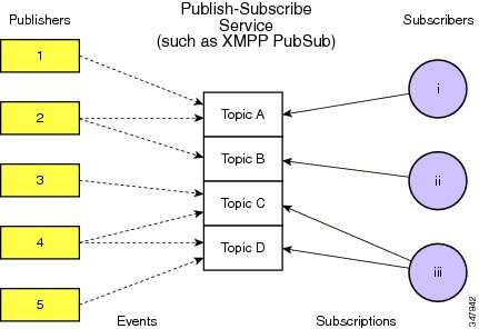
XMPP PubSub is a protocol extension for generic publish-subscribe functionality, specified in XEP-0060. The protocol enables XMPP entities to create nodes (topics) at a pubsub service and publish information at those nodes; an event notification (with or without payload) is then broadcast to all entities that have subscribed to the node. Pubsub therefore adheres to the classic observer design pattern and can serve as the foundation for a wide variety of applications, including news feeds, content syndication, rich presence, geo-location, workflow systems, network management systems, and any other application that requires event notifications.
Figure 2-1 shows the XMPP publish-subscribe service flow.
Figure 2-1 XMPP Publish-Subscribe Service Flow
Prime Analytics only supports the XMPP pubsub mechanism and is tested with two products: Cisco Conductor for Videoscape and Openfire, an instant messaging and groupchat server that uses XMPP licensed under the Apache License 2.0.
The Prime Analytics XMPP handler functions as the subscriber. It receives the XMPP messages and parses the payload using the XML handler.
To connect to the pubsub server, you must configure the communications parameters listed in Table 2-5.
XSLT-Based XML Handler
By default, you can use the XSLT to parse the payload, so you need to specify the XSLT path for XML parsing. For example:
<handlers><chain id="xmpp"><xmpp><xmpphostname>10.74.125.169</xmpphostname><port>5222</port><subscribeuser>pub@crdc-c210-169/conductor</subscribeuser><password>pub</password><isDebug>true</isDebug><pubsubId>pubsub.crdc-c210-169</pubsubId><pubsubNode>cisco.pubsub</pubsubNode></xmpp><xml><xslt>/var/opt/primea/projects/acal/ACAL_Setup.xslt</xslt></xml><text><delimiter>,</delimiter></text><commit><rows>200</rows></commit><pump><type>COPY</type><mode>CSV</mode><schema>acal</schema><stream>setup</stream></pump></chain></handlers>Multiple Pubsub Nodes Support
The XMPP handler uses multiple chains to support multiple nodes and topics. Each message type is defined in one chain, and the XSLT contains the node and topic name. The following examples shows two nodes, truviso and primea:
<handlers><chain id="xmpp"><custom><xmpphostname>10.75.162.230</xmpphostname><port>5222</port><subscribeuser>utruviso@client.com</subscribeuser><password>cisco123</password><isDebug>true</isDebug><pubsubId>ps.com</pubsubId><pubsubNode>truviso</pubsubNode></custom><custom><xslt>/var/opt/primea/projects/xmpp/transform_truviso.xslt</xslt></custom><text><delimiter>,</delimiter></text><pump><type>COPY</type><mode>CSV</mode><schema>xmpp</schema><stream>tvshow</stream></pump></chain><chain id="xmpp_primea"><custom><xmpphostname>10.75.162.230</xmpphostname><port>5222</port><subscribeuser>uprimea@client.com</subscribeuser><password>cisco123</password><isDebug>true</isDebug><pubsubId>ps.com</pubsubId><pubsubNode>primea</pubsubNode></custom><custom><xslt>/var/opt/primea/projects/xmpp/transform_primea.xslt</xslt></custom><text><delimiter>,</delimiter></text><pump><type>COPY</type><mode>CSV</mode><schema>xmpp</schema><stream>tvshow</stream></pump></chain></handlers>One Pubsub Node With Multiple Topics
One pubsub node could send out multiple formats of messages or payload, such as the setup and tear down messages are sent to the same pubsub node. Take the ACAL setup and tear down messages as the example. Two part should be updated, one is XSLT and another is the db pump part.
•
<xsl:stylesheet version="1.0"xmlns:xsl="http://www.w3.org/1999/XSL/Transform"><xsl:template match="ACAL/report"><xsl:choose><xsl:when test="@type='setup'"><xsl:value-of select="@type" />,<xsl:value-of select="@id" />,<xsl:value-of select="@seq" />,<xsl:value-of select="@time" />,"<xsl:value-of select="label" />","<xsl:value-of select="assetName" />",<xsl:value-of select="assetSrc" />,<xsl:value-of select="endpointID" />,<xsl:value-of select="platformClass" />,<xsl:value-of select="platformMake" />,<xsl:value-of select="platformModel" />,<xsl:value-of select="platformApplication" />,<xsl:value-of select="platformAppVer" />,</xsl:when><xsl:when test="@type='teardown'"><xsl:value-of select="@type" />,<xsl:value-of select="@id" />,<xsl:value-of select="@seq" />,<xsl:value-of select="@time" />,<xsl:value-of select="reason" />,</xsl:when></xsl:choose></xsl:template></xsl:stylesheet>•
<handlers><chain id="xmpp"><xmpp><xmpphostname>172.20.127.147</xmpphostname><port>5222</port><subscribeuser>utruviso@client.com</subscribeuser><password>cisco123</password><isDebug>true</isDebug><pubsubId>ps.com</pubsubId><pubsubNode>truviso</pubsubNode></xmpp><xml><xslt>ACAL_Setup_C.xslt</xslt></xml><text><delimiter>,</delimiter></text><commit><rows>2</rows></commit><multistream><pumpkeyindex>1</pumpkeyindex><pumps><pump key="setup"><type>COPY</type><mode>CSV</mode><schema>acal</schema><stream>setup</stream></pump><pump key="teardown"><type>COPY</type><mode>CSV</mode><schema>acal</schema><stream>teardown</stream></pump></pumps></multistream></chain></handlers>Troubleshooting Handlers and Connectors
If no data is received by the connector or handler, check network connectivity:
1.
2.
3.
4.
5.
6.
7.
If you receive an "ERROR: extra data after last expected column" while using the XSLT-based XML handler, check whether a comma or special character is the same delimiter defined in text part. It parses original messages into several fields. This causes the database exceptions because there are more fields than the db schema defined, so the delimiter within the message is ignored.
<xsl:stylesheet version="1.0"xmlns:xsl="http://www.w3.org/1999/XSL/Transform" xmlns:df="http://jabber.org/protocol/pubsub"><xsl:template match="/"><xsl:for-each select="df:ACAL/df:report"><xsl:value-of select="@type" />,<xsl:value-of select="@id" />,<xsl:value-of select="@seq" />,<xsl:value-of select="@time" />,"<xsl:value-of select="df:label" />","<xsl:value-of select="df:assetName" />",<xsl:value-of select="df:assetSrc" />,<xsl:value-of select="df:endpointID" />,<xsl:value-of select="df:platformClass" />,<xsl:value-of select="df:platformMake" />,<xsl:value-of select="df:platformModel" />,<xsl:value-of select="df:platformApplication" />,<xsl:value-of select="df:platformAppVer" />,</xsl:for-each></xsl:template>Creating Continuous Queries
Continuous queries are persistent inquiries that operate over streams and tables. Continuous queries are created through XML definition files.
To validate the continuous query XML configuration file:
Step 1
<!ENTITY connectors SYSTEM "include-queries.xml">Step 2
&queries;This allows you to configure all continuous queries in the include-queries.xml file rather than within the data.xml file itself.
Step 3
Step 4
Creating Static Queries
Static queries operate over data dimension tables and archived continuous query data tables. Static queries are the same as traditional relational queries. Like continuous queries, static queries are created through XML definition files.
To validate the XML configuration file for static queries:
Step 1
<!ENTITY connectors SYSTEM "include-staticqueries.xml">Step 2
&staticqueries;This allows you to configure all continuous queries in the include-staticqueries.xml file rather than within the data.xml file itself.
Step 3
Step 4
Compiling the Prime Analytics Project
After you have configured the Prime Analytics connectors, handlers, and the continous or static queries, you must compile and then run your project.
To compile your project, enter:
$ ./build-local.shIf the build compiles with no errors, the following directories are created in the project's root directory:
•
•
•
These directories contain the runtime distribution of the your Prime Analytics project.
Starting and Monitoring the Project
After your project is compiled, verify the TruCQ engine is started and any associated DDL has been executed. Then enter the following commands to start and stop your project:
To start the project
./start.shTo stop the project:
./stop.sh
To monitor your application activity, review the log files in apache-tomcat/logs/. The truviso.log is the primary log file. However, some startup errors might only appear in the catalina.out file. Some problems that can prevent application startup might be better analyzed by looking at errors in the database log files:
tail $CQLOGWhere $CQLOG is the directory containing the CQ engine database log.
To view your data using the Prime Analytics BI platform, open your browser and navigate to http://servername:8080/MyProject Log in with the default credentials: admin/admin. You can leave the locale at its default.
For information about creating dashboards and reports from the BI platform, see the following topics:
•