-
User Guide for the Cisco Mobile Wireless Transport Manager 6.0
-
About this Guide
-
Overview
-
Configuring Security
-
Setting Up Your Server
-
Getting Started
-
Basic Operations
-
Understanding Basic Object Functions
-
Managing Views
-
Understanding Detailed Object Functions
-
Managing Events
-
Viewing Network Topology
-
Accessing Data from the Web Interface
-
Managing ITP Reports
-
Editing an ITP Route Table File
-
Editing an ITP Global Title Translation Table
-
Editing ITP MLR Address Table Files
-
Object Map Reference
-
Command Reference
-
FAQs
-
Troubleshooting MWTM and the Network
-
Status Definitions
-
MIB Reference
-
Trap Reference
-
Configuring MWTM to Run with Various Networking Options
-
Archived Reports File Formats
-
MWTM Ports
-
Open Source License Notices for the Cisco Mobile Wireless Transport Manager
-
Glossary
-
Index
-
 Feedback
Table Of Contents
Understanding Basic Object Functions
Right-Click Menu for All Objects
Application Server Processes Table
Application Server Process Associations Table
Signaling Gateway Mated Pairs Table
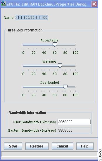
Editing Properties for a RAN-O Backhaul
Deleting an Object from Your Network
Deleting an Object from the MWTM Database
Deleting a Node from the MWTM Discovery Dialog
Unmanaging and Managing Nodes or ITP Signaling Points
Excluding Nodes or ITP Signaling Points from a View
Ignoring and Unignoring Objects
Understanding Basic Object Functions
You can use the Cisco Mobile Wireless Transport Manager (MWTM) to view basic information about any discovered MWTM object, including its associated objects, events, status, and other important information.
To view basic information for an object, click the turner beside Summary Lists in the navigation tree of the MWTM main window, then select one of these objects:
Note
Objects only appear if your network contains that particular object type.
This chapter contains:
•
•
•
Displaying Object Windows
To display an object window, in the MWTM main window, under Summary Lists in the navigation tree, select the object type. The object window appears in the right pane.
Note
Example:
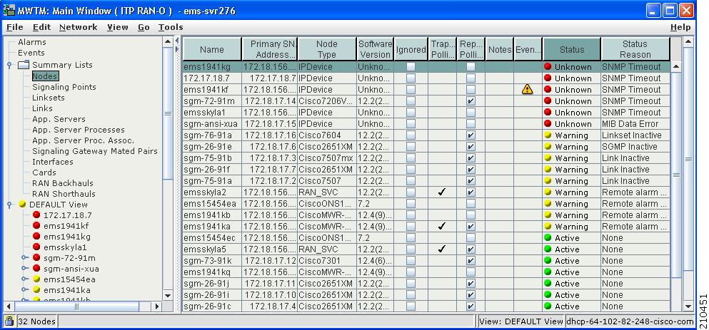
To display the nodes table, choose Summary Lists > Nodes. The nodes table appears.
Figure 6-1 Node Window
Object windows provide information about all objects of a specific type that the MWTM has discovered.
Object windows can contain:
•
•
•
•
Right-Click Menu for All Objects
To see the right-click menu for all objects, in the MWTM main window, under Summary Lists in the navigation tree, select the object type and right-click on it. The right-click menu contains:
Note
Nodes Table
The nodes table displays information about nodes that the MWTM has discovered. To display the nodes table, choose Summary Lists > Nodes.
You can resize each column, or sort the table based on the information in one of the columns. By default, this table is sorted by Status, and the MWTM displays all of the columns in the nodes table except Internal ID, CLLI Code, Uptime, Reboot Reason, Process Traps, and Last Status Change.
For detailed information on working within tables, see Navigating Table Columns, page 5-23.
The nodes table contains:
Internal ID
Internal ID of the node. The internal ID is a unique ID for every object, which the MWTM assigns for its own internal use. This ID can also be useful when the TAC is debugging problems.
Name
Name of the node.
Primary SNMP Address
IP address of the node, which SNMP uses to poll the node. (There might be other IP addresses on the node that are not the primary SNMP address.)
CLLI Code (ITP only)
Common Language Location Identification code for the node. A CLLI code is a standardized 11-character identifier that uniquely identifies the geographic location of the node. If the node has no CLLI code configured, this field is blank.
Node Type
Type of node. Node types can be specific to ITP, RAN-O, or generic to both.
ITP specific nodes include:
•
•
•
•
•
•
RAN-O specific nodes include:
•
•
•
•
Generic nodes include:
•
•
Software Version
Version of node's software.
Uptime
Time the node has been up, in days, hours, minutes, and seconds.
Reboot Reason
Reason for the last reboot of the node.
Ignored
Indicates whether to include the node when aggregating and displaying MWTM status information:
•
•
Note
Users with authentication level Power User (level 2) and higher can edit this field.
Process Traps
Indicates whether the MWTM should process traps from this node. This field is read-only.
Trap Polling
Indicates whether trap polling is enabled for this node. This field is read-only.
•
•
Report Polling
Indicates whether report polling is enabled for this node. This field is read-only.
•
•
Notes
Indicates whether a note is associated with the node.
Events
Indicates whether a recent event is associated with the node. (Even if the server purges all of the events associated with the node, the MWTM continues to display the event icon in this field.) To delete the:
•
•
Note
Last Status Change
Date and time that the status of the node last changed.
Status
Current status of the node. Possible values are:
Active (green)
Discovering (cyan)
Polling (cyan)
Unknown (red)
Unmanaged (gray)
Waiting (gray)
Warning (yellow)
For detailed definitions of each status, see Status Definitions for Signaling Gateway Mated Pairs, page E-7.
Status Reason
Reason for the current status of the node.
For a full list of possible reasons, see the stateReasons.html file. If you installed the MWTM in:
•
•
If the cell is too small to show all of the status reason, place the cursor over the cell to see the full text in a tooltip.
The status reasons appear in order of decreasing magnitude. If two or more reasons apply, the reason of greatest magnitude appears first.
If the status reason is Unsupported Configuration, correct the configuration and enter the mwtm cleandiscover command to delete all current network data and begin a discovery of the network. If the status reason remains Unsupported Configuration, enter the mwtm clean command to restore the MWTM server to a state that would exist after a new installation of the MWTM, excluding the log files, which the MWTM retains. To also remove the log files, enter the mwtm cleanall command. For more information on the use of these commands, see the Command Reference, page B-1.
Signaling Points Table
The signaling points table displays information about the signaling points that the MWTM has discovered. To display the signaling points table, choose Summary Lists > Signaling Points.
You can resize each column, or sort the table based on the information in one of the columns. By default, the MWTM displays all of the columns in the signaling points table except Internal ID, Instance Number, and Last Status Change.
For detailed information on working within tables, see the Navigating Table Columns, page 5-23.
The signaling points table contains:
Internal ID
Internal ID of the signaling point. The internal ID is a unique ID for every object, which the MWTM assigns for its own internal use. It can also be useful when the TAC is debugging problems.
Name
Name of the signaling point.
Node
Name of the node associated with this signaling point.
Instance Number
Number of the instance associated with the signaling point.
Network Name
Name of the instance associated with the signaling point.
Point Code
Primary point code of the signaling point.
Variant
SS7 protocol variant. Valid variants are:
•
•
•
•
•
Network Indicator
Determines the type of call that is being placed. Valid values are:
•
•
•
•
Ignored
Indicates whether to include the signaling point when aggregating and displaying MWTM status information:
•
•
Users with authentication level Power User (level 2) and higher can edit this field.
Notes
Indicates whether a note is associated with the signaling point.
Events
Indicates whether a recent event is associated with the signaling point. (Even if the server purges all of the events associated with the signaling point, the MWTM continues to display the event icon in this field.)
Note
Last Status Change
Date and time that the status of the signaling point last changed.
Status
Current status of the signaling point. Possible values are:
Active (green)
Unknown (red)
Unmanaged (gray)
Warning (yellow)
For detailed definitions of each status, see Status Definitions for Signaling Points, page E-7.
Status Reason
Reason for the current status of the signaling point.
For a full list of possible reasons, see the stateReasons.html file. If you installed the MWTM in:
•
•
If the cell is too small to show all of the status reason, place the cursor over the cell to see the full status reason in a mouse over help popup.
The status reasons are listed in order of decreasing magnitude. If two or more reasons apply, the reason of greatest magnitude appears.
If the status reason is Unsupported Configuration, correct the configuration and enter the mwtm cleandiscover command to delete all current network data and begin a discovery of the network. If the status reason remains Unsupported Configuration, enter the mwtm clean command to restore the MWTM server to a state that would exist after a new installation of the MWTM, excluding the log files, which the MWTM retains. To also remove the log files, enter the mwtm cleanall command. For more information on the use of these commands, see the Command Reference, page B-1.
Linksets Table
The linksets table displays information about the linksets that the MWTM has discovered. To display the linksets table, choose Summary Lists > Linksets.
Tip
You can resize each column, or sort the table based on the information in one of the columns. By default, this table is sorted by Status, and the MWTM displays all of the columns in the linksets table except Internal ID, Node, SP, Congested Links, and Last Status Change.
For detailed information on working within tables, see Navigating Table Columns, page 5-23.
The linksets table contains:
Internal ID
Internal ID of the linkset. The internal ID is a unique ID for every object, which the MWTM assigns for its own internal use. It can also be useful when the TAC is debugging problems.
Name
Name of the linkset.
Node
Node associated with the linkset.
Signaling Point
Signaling point associated with the linkset.
Local Point Code
Point code of the primary signaling point for the linkset.
Adj Point Code
Point code of the adjacent signaling point for the linkset.
Linkset Type
Type of linkset, which the MWTM determines by examining the links defined in the linkset. Possible linkset types are:
•
•
•
•
•
Note
•
Links
Total number of links in the linkset.
Active Links
Number of links in the linkset that are Active.
Congested Links
Number of links in the linkset that are Congested.
Ignored
Indicates whether to include the linkset when aggregating and displaying MWTM status information:
•
•
Users with authentication level Power User (level 2) and higher can edit this field.
Notes
Indicates whether a note is associated with the linkset.
Events
Indicates whether there is a recent event associated with the linkset. (Even if the server purges all of the events associated with the linkset, the MWTM continues to display the event icon in this field.) To delete the Event icon from MWTM displays for:
•
•
Note
Last Status Change
Date and time that the status of the linkset last changed.
Status
Current status of the linkset. Possible values are:
Active (green)
Shutdown (blue)
Unavailable (red)
Unknown (red)
Warning (yellow)
For detailed definitions of each status, see Status Definitions for Linksets, page E-6.
Status Reason
Reason for the current status of the signaling gateway-mated pair.
For a full list of possible reasons, see the stateReasons.html file. If you installed the MWTM in:
•
•
If the cell is too small to show all of the status reason, place the cursor over the cell to see the full text in a tooltip.
The status reasons are listed in order of decreasing magnitude. If two or more reasons apply, the reason of greatest magnitude appears first.
If the status reason is Unsupported Configuration, correct the configuration and enter the mwtm cleandiscover command to delete all current network data and begin a discovery of the network. If the status reason remains Unsupported Configuration, enter the mwtm clean command to restore the MWTM server to a state that would exist after a new installation of the MWTM, excluding the log files, which the MWTM retains. To also remove the log files, enter the mwtm cleanall command. For more information on the use of these commands, see the Command Reference, page B-1.
Links Table
The links table displays information about the links that the MWTM has discovered. To display the links table, choose Summary Lists > Links.
You can resize each column, or sort the table based on the information in one of the columns. By default, this table is sorted by Status, and the MWTM displays all of the columns in the links table except Internal ID, Congestion Level, and Last Status Change.
For detailed information on working within tables, see Navigating Table Columns, page 5-23.
The links table contains:
Internal ID
Internal ID of the link. The internal ID is a unique ID for every object, which the MWTM assigns for its own internal use. This ID can also be useful when the TAC is debugging problems.
Node
Name of the node associated with the link.
Signaling Point
Name of the signaling point associated with the link.
Linkset
Name of the linkset associated with the link.
SLC
Signaling link code (SLC) ID for the link.
Type
Type of link. Possible link types are:
•
•
•
•
Congestion Level
Indicates the level of congestion on the link. A link is congested if it has too many packets waiting to be sent. This condition could result from the failure of an element in your network.
Possible values for the Congestion Level field are None, indicating no congestion, and 1 to 3, indicating levels of congestion from very light (1) to very heavy (3).
Ignored
Indicates whether to include the link when aggregating and displaying MWTM status information:
•
•
Users with authentication level Power User (level 2) and higher can edit this field.
Notes
Indicates whether a note is associated with the link.
Events
Indicates whether a recent event is associated with the link. (Even if the server purges all of the events associated with the link, the MWTM continues to display the event icon in this field.) To delete the Event icon from MWTM displays for:
•
•
Note
Last Status Change
Date and time that the status of the link last changed.
Status
Current status of the link. Possible values are:
Active (green)
Blocked (red)
Failed (red)
InhibitLoc (blue)
InhibitRem (blue)
Shutdown (blue)
Unknown (red)
Warning (yellow)
For detailed definitions of each status, see Status Definitions for Links, page E-5.
Status Reason
Reason for the current status of the signaling gateway-mated pair.
For a full list of possible reasons, see the stateReasons.html file. If you installed the MWTM in:
•
•
If the cell is too small to show all of the status reason, place the cursor over the cell to see the full text in a tooltip.
The status reasons appear in order of decreasing magnitude. If two or more reasons apply, the reason of greatest magnitude appears first.
If the status reason is Unsupported Configuration, correct the configuration and enter the mwtm cleandiscover command to delete all current network data and begin a discovery of the network. If the status reason remains Unsupported Configuration, enter the mwtm clean command to restore the MWTM server to a state that would exist after a new installation of the MWTM, excluding the log files, which the MWTM retains. To also remove the log files, enter the mwtm cleanall command. For more information on the use of these commands, see the Command Reference, page B-1.
Application Servers Table
The application servers table displays information about the application servers that the MWTM has discovered. To display the application servers table, choose Summary Lists > App. Servers.
You can resize each column, or sort the table based on the information in one of the columns. By default, this table is sorted by Status, and the MWTM displays all of the columns in the application servers table except Internal ID, Protocol, Routing Key, Traffic Mode, and Last Status Change.
For detailed information on working within tables, see Navigating Table Columns, page 5-23.
The application servers table contains:
Internal ID
Internal ID of the application server. The internal ID is a unique ID for every object, that the MWTM assigns for its own internal use. This ID can also be useful when the TAC is debugging problems.
Name
Name of the application server.
Node
Name of the node associated with the application server.
Signaling Point
Name of the signaling point associated with the application server.
Protocol
Protocol associated with the application server. Possible values are:
•
•
Routing Key
Routing key associated with the application server. The application server bases its routing decisions on the routing key value.
Traffic Mode
Method by which the application server forwards requests to its active application server processes. Possible values are:
•
•
•
•
•
Application Server Process Associations
Total number of application server processes associated with the application server.
Active ASP Associations
Number of currently active application server processes associated with the application server.
Ignored
Indicates whether to include the application server when aggregating and displaying MWTM status information:
•
•
Users with authentication level Power User (level 2) and higher can edit this field.
Notes
Indicates whether a note is associated with the application server.
Events
Indicates whether a recent event is associated with the application server. (Even if the server purges all of the events associated with the application server, the MWTM continues to display the event icon in this field.) To delete the Event icon from MWTM displays for:
•
•
Note
Last Status Change
Date and time that the status of the application server last changed.
Status
Current status of the application server. Possible values are:
Active (green)
Down (red)
Inactive (red)
Pending (red)
Shutdown (blue)
Unknown (red)
Warning (yellow)
For detailed definitions of each status, see Status Definitions for Application Servers, page E-3.
Status Reason
Reason for the current status of the signaling gateway-mated pair.
For a full list of possible reasons, see the stateReasons.html file. If you installed the MWTM in:
•
•
If the cell is too small to show all of the status reason, place the cursor over the cell to see the full text in a tooltip.
The status reasons are listed in order of decreasing magnitude. If two or more reasons apply, the reason of greatest magnitude appears first.
If the status reason is Unsupported Configuration, correct the configuration and enter the mwtm cleandiscover command to delete all current network data and begin a discovery of the network. If the status reason remains Unsupported Configuration, enter the mwtm clean command to restore the MWTM server to a state that would exist after a new installation of the MWTM, excluding the log files, which the MWTM retains. To also remove the log files, enter the mwtm cleanall command. For more information on the use of these commands, see the Command Reference, page B-1.
Application Server Processes Table
The application server processes table displays information about the application server processes that the MWTM has discovered. To display the application server processes table, choose Summary Lists > App. Server Processes.
You can resize each column, or sort the table based on the information in one of the columns. By default, this table is sorted by Status, and the MWTM displays all of the columns in the application server processes table except Internal ID and Last Status Change.
For detailed information on working within tables, see Navigating Table Columns, page 5-23.
The application server processes table contains:
Internal ID
Internal ID of the application server process. The internal ID is a unique ID for every object, that the MWTM assigns for its own internal use. This ID can also be useful when the TAC is debugging problems.
Name
Name of the application server process.
Node
Name of the node associated with the application server process.
Local IP Address
Local IP address that the application server process is currently using.
Local Port
Local port number that the application server process is currently using.
Ignored
Indicates whether to include the application server process when aggregating and displaying MWTM status information:
•
•
Users with authentication level Power User (level 2) and higher can edit this field.
Notes
Indicates whether a note is associated with the application server process.
Events
Indicates whether a recent event is associated with the application server process. (Even if the server purges all of the events associated with the application server process, the MWTM continues to display the event icon in this field.) To delete the Event icon from MWTM displays for:
•
•
Note
Last Status Change
Date and time that the status of the application server process last changed.
Status
Current status of the application server process. Possible values are:
Unknown (red)
Unmanaged (gray)
For detailed definitions of each status, see Status Definitions for Application Server Processes, page E-3.
Status Reason
Reason for the current status of the application server process.
For a full list of possible reasons, see the stateReasons.html file. If you installed the MWTM in:
•
•
If the cell is too small to show all of the status reason, place the cursor over the cell to see the full text in a tooltip.
The status reasons are listed in order of decreasing magnitude. If two or more reasons apply, the reason of greatest magnitude appears first.
If the status reason is Unsupported Configuration, correct the configuration and enter the mwtm cleandiscover command to delete all current network data and begin a discovery of the network. If the status reason remains Unsupported Configuration, enter the mwtm clean command to restore the MWTM server to a state that would exist after a new installation of the MWTM, excluding the log files, which the MWTM retains. To also remove the log files, enter the mwtm cleanall command. For more information on the use of these commands, see the Command Reference, page B-1.
Application Server Process Associations Table
The application server process associations table displays information about the application server process associations that the MWTM has discovered. To display the application server process associations table, choose Summary Lists > App. Server Proc. Assoc.
You can resize each column, or sort the table based on the information in one of the columns. By default, this table is sorted by Status, and the MWTM displays all of the columns in the application server process associations table except Internal ID, Congestion Level, and Last Status Change.
For detailed information on working within tables, see Navigating Table Columns, page 5-23.
The application server process associations table contains:
Internal ID
Internal ID of the application server process association. The internal ID is a unique ID for every object, that the MWTM assigns for its own internal use. The ID can also be useful when the TAC is debugging problems.
Name
Name of the application server process association.
Node
Name of the node associated with the application server process association.
Signaling Point
Name of the signaling point associated with the application server process association.
Application Server
Name of the application server associated with the application server process association.
Protocol
Protocol associated with the application server process association. Possible values are:
•
•
Congestion Level
Indicates the level of congestion of an application server process association. An application server process association is congested if it has too many packets waiting to be sent. This condition could result from the failure of an element in your network.
Possible values for the Congestion Level field are None, indicating no congestion, and 1 to 7, indicating levels of congestion from very light (1) to very heavy (7).
Ignored
Indicates whether to include the application server process association when aggregating and displaying MWTM status information:
•
•
Users with authentication level Power User (level 2) and higher can edit this field.
Notes
Indicates whether a note is associated with the application server process association.
Events
Indicates whether a recent event is associated with the application server process association. (Even if the server purges all of the events associated with the application server process association, the MWTM continues to display the event icon in this field.) To delete the Event icon from MWTM displays for:
•
•
Note
Last Status Change
Date and time that the status of the application server process association last changed.
Status
Current status of the application server process association. Possible values are:
Active (green)
Blocked (red)
Down (red)
Inactive (red)
Pending (red)
Shutdown (blue)
Unknown (red)
Warning (yellow)
For detailed definitions of each status, see Status Definitions for Application Server Process Associations, page E-3.
Status Reason
Reason for the current status of the application server process association.
For a full list of possible reasons, see the stateReasons.html file. If you installed the MWTM in:
•
•
If the cell is too small to show all of the status reason, place the cursor over the cell to see the full text in a tooltip.
The status reasons are listed in order of decreasing magnitude. If two or more reasons apply, the reason of greatest magnitude appears first.
Status Reason
(continued)
If the status reason is Unsupported Configuration, correct the configuration and enter the mwtm cleandiscover command to delete all current network data and begin a discovery of the network. If the status reason remains Unsupported Configuration, enter the mwtm clean command to restore the MWTM server to a state that would exist after a new installation of the MWTM, excluding the log files, which the MWTM retains. To also remove the log files, enter the mwtm cleanall command. For more information on the use of these commands, see the Command Reference, page B-1.
Signaling Gateway Mated Pairs Table
The signaling gateway-mated pairs table displays information about the signaling gateway-mated pairs that the MWTM has discovered. To display the signaling gateway-mated pairs table, choose Summary Lists > Signaling Gateway Mated Pairs.
You can resize each column, or sort the table based on the information in one of the columns. By default, this table is sorted by Status, and the MWTM displays all of the columns in the signaling gateway-mated pairs table except Internal ID and Congestion Level.
For detailed information on working within tables, see Navigating Table Columns, page 5-23.
The signaling gateway-mated pairs table contains:
Internal ID
Internal ID of the signaling gateway-mated pair. The internal ID is a unique ID for every object, that the MWTM assigns for its own internal use. The ID can also be useful when the TAC is debugging problems.
Name
Name of the signaling gateway-mated pair.
Mate
Name of the node associated with the mate of the signaling gateway-mated pair.
Node
Name of the node associated with the signaling gateway-mated pair.
Congestion Level
Indicates the congestion level of a signaling gateway-mated pair. A signaling gateway-mated pair is congested if it has too many packets waiting to be sent. This condition could result from the failure of an element in your network.
Possible values for the Congestion Level field are None, indicating no congestion, and 1 to 7, indicating levels of congestion from very light (1) to very heavy (7).
Ignored
Indicates whether to include the signaling gateway-mated pair when aggregating and displaying MWTM status information:
•
•
Users with authentication level Power User (level 2) and higher can edit this field.
Notes
Indicates whether a note is associated with the signaling gateway-mated pair.
Events
Indicates whether a recent event is associated with the signaling gateway-mated pair. (Even if the server purges all of the events associated with the signaling gateway-mated pair, the MWTM continues to display the event icon in this field.) To delete the Event icon from MWTM displays for:
•
•
Note
Last Status Change
Date and time that the status of the signaling gateway-mated pair last changed.
Status
Current status of the signaling gateway-mated pair. Possible values are:
Active (green)
Down (red)
Inactive (red)
Shutdown (blue)
Unknown (red)
Warning (yellow)
For detailed definitions of each status, see Status Definitions for Signaling Gateway Mated Pairs, page E-7.
Status Reason
Reason for the current status of the signaling gateway-mated pair.
For a full list of possible reasons, see the stateReasons.html file. If you installed the MWTM in:
•
•
If the cell is too small to show all of the status reason, place the cursor over the cell to see the full text in a tooltip.
The status reasons are listed in order of decreasing magnitude. If two or more reasons apply, the reason of greatest magnitude appears first.
If the status reason is Unsupported Configuration, correct the configuration and enter the mwtm cleandiscover command to delete all current network data and begin a discovery of the network. If the status reason remains Unsupported Configuration, enter the mwtm clean command to restore the MWTM server to a state that would exist after a new installation of the MWTM, excluding the log files, which the MWTM retains. To also remove the log files, enter the mwtm cleanall command. For more information on the use of these commands, see the Command Reference, page B-1.
Interfaces Table
The interfaces table displays information about the ITP or RAN interfaces that the MWTM has discovered. To display the interfaces table, choose Summary Lists > Interfaces.
You can resize each column, or sort the table based on the information in one of the columns. By default, this table is sorted by Status, and the MWTM displays all of the columns in the interfaces table except Interface Type, Last Status Change, Admin Status, and Operational Status.
For detailed information on working within tables, see Navigating Table Columns, page 5-23.
The interfaces table contains:
Name
Name of the interface. The node specifies the name of the interface.
Node
Name of the node with the interface.
Speed
Speed of the interface in bits per second.
Interface Index
Unique numeric identifier of the interface. This identifier appears in the interface table (ifTable).
Maximum Packet Size
The maximum packet size that traverses the interface in bytes.
Physical Address
The physical address of the interface. If a physical address does not apply to the interface, N/A appears in the table cell.
Ignored
Indicates whether to include the interface when aggregating and displaying MWTM status information:
•
•
Users with authentication level Power User (level 2) and higher can edit this field.
Notes
Indicates whether a note is associated with the interface.
Events
Indicates whether a recent event is associated with the interface. (Even if the server purges all of the events associated with the interface, the MWTM continues to display the event icon in this field.) To delete the Event icon from MWTM displays for:
•
•
Note
Last Status Change
Date and time that the status of the interface last changed.
Status
Current status of the interface. Possible values are:
Active (green)
Down (red)
Inactive (red)
Shutdown (blue)
Unknown (red)
Warning (yellow)
For detailed definitions of each status, see Status Definitions for RAN-O Interfaces, page E-7.
Admin Status
Desired state of the interface:
•
•
•
•
For detailed definitions of each status, see Admin Status, page E-8.
Operational Status
Current operational state of the interface:
•
•
•
•
•
•
•
For detailed definitions of each status, see Operational Status, page E-8.
Status Reason
Reason for the current status of the interface.
For a full list of possible reasons, see the stateReasons.html file. If you installed the MWTM in:
•
•
If the cell is too small to show all of the status reason, place the cursor over the cell to see the full text in a tooltip.
Status Reason
(continued)
The status reasons are listed in order of decreasing magnitude. If two or more reasons apply, the reason of greatest magnitude appears first.
If the status reason is Unsupported Configuration, correct the configuration and enter the mwtm cleandiscover command to delete all current network data and begin a discovery of the network. If the status reason remains Unsupported Configuration, enter the mwtm clean command to restore the MWTM server to a state that would exist after a new installation of the MWTM, excluding the log files, which the MWTM retains. To also remove the log files, enter the mwtm cleanall command. For more information on the use of these commands, see the Command Reference, page B-1.
Cards Table
The cards table displays information about the cards in the ONS 15454 RAN-O node that the MWTM has discovered. To display the cards table, choose Summary Lists > Cards.
You can resize each column, or sort the table based on the information in one of the columns. By default, this table is sorted by Status, and the MWTM displays all of the columns in the cards table except Internal ID, cardModelName, Last Status Change, Status Reason, Hardware Version, Firmware Version, and Software Version.
For detailed information on working within tables, see Navigating Table Columns, page 5-23.
The cards table contains:
Internal ID
Internal ID of the card. The internal ID is a unique ID for every object, that the MWTM assigns for its own internal use. The ID can also be useful when the TAC is debugging problems.
Name
Name of the card. The node specifies the name of the card.
Node
Name of the node in which the card resides.
Card Type
Type of the card in the node.
Model Name
Model name of the card (can include the part number).
Description
Description of the card.
Slot Number
The slot number of the card in the node.
Ignored
Indicates whether to include the card when aggregating and displaying MWTM status information:
•
•
Users with authentication level Power User (level 2) and higher can edit this field.
Notes
Indicates whether a note is associated with the card.
Events
Indicates whether a recent event is associated with the card. (Even if the server purges all of the events associated with the card, the MWTM continues to display the event icon in this field.) To delete the Event icon from MWTM displays for:
•
•
Note
Last Status Change
Date and time that the status of the card last changed.
Status
Current status of the card. Possible values are:
Active (green)
Down (red)
Inactive (red)
Shutdown (blue)
Unknown (red)
Warning (yellow)
For detailed definitions of each status, see Status Definitions for Cards, page E-10.
Status Reason
Reason for the current status of the card.
For a full list of possible reasons, see the stateReasons.html file. If you installed the MWTM in:
•
•
If the cell is too small to show all of the status reason, place the cursor over the cell to see the full text in a tooltip.
The status reasons are listed in order of decreasing magnitude. If two or more reasons apply, the reason of greatest magnitude appears first.
If the status reason is Unsupported Configuration, correct the configuration and enter the mwtm cleandiscover command to delete all current network data and begin a discovery of the network. If the status reason remains Unsupported Configuration, enter the mwtm clean command to restore the MWTM server to a state that would exist after a new installation of the MWTM, excluding the log files, which the MWTM retains. To also remove the log files, enter the mwtm cleanall command. For more information on the use of these commands, see the Command Reference, page B-1.
Hardware Version
Hardware version of the card.
Firmware Version
Firmware version of the card.
Software Version
Software version of the card.
RAN Backhauls Table
The RAN backhauls table displays information about the RAN backhauls that the MWTM has discovered. To display the RAN backhauls table, choose Summary Lists > RAN Backhauls.
You can resize each column, or sort the table based on the information in one of the columns. By default, this table is sorted by Status, and the MWTM displays all of the columns in the table except Internal ID, Type, User Bandwidth, System Bandwidth, Last Status Change, Acceptable Threshold, Warning Threshold, and Overloaded Threshold.
For detailed information on working within tables, see Navigating Table Columns, page 5-23.
The RAN backhauls table contains:
Internal ID
Internal ID of the RAN backhaul. The internal ID is a unique ID for every object, that the MWTM assigns for its own internal use. The ID can also be useful when the TAC is debugging problems.
Name
Name of the RAN backhaul.
Node
Name of the node on which this RAN backhaul resides.
Location
Location of the node (either at the cell site or the aggregation node site).
Peer Name
Name of the object's peer.
Peer Node
Name of the node to which the peer object belongs.
Type
Indicates whether the RAN backhaul is a normal backhaul or a virtual backhaul (see Creating Virtual RAN Backhauls, page 8-136).
User Bandwidth
The bandwidth that the user specified for the backhaul. To change this value, see Editing Properties for a RAN-O Backhaul.
System Bandwidth
The bandwidth that the system specifies for the backhaul. To change this value, see Editing Properties for a RAN-O Backhaul.
Ignored
Indicates whether to include the RAN backhaul when aggregating and displaying MWTM status information:
•
•
Users with authentication level Power User (level 2) and higher can edit this field.
Notes
Indicates whether a note is associated with the RAN backhaul.
Events
Indicates whether a recent event is associated with the RAN backhaul. (Even if the server purges all of the events associated with the RAN backhaul, the MWTM continues to display the event icon in this field.) To delete the Event icon from MWTM displays for:
•
•
Note
Last Status Change
Date and time that the status of the backhaul last changed.
Status
Current status of the RAN backhaul. Possible values are:
Active (green)
Failed (red)
Warning (yellow)
For detailed definitions of each status, see Status Definitions for RAN-O Backhauls, page E-10.
Status Reason
Reason for the current status of the card.
For a full list of possible reasons, see the stateReasons.html file. If you installed the MWTM in:
•
•
If the cell is too small to show all of the status reason, place the cursor over the cell to see the full text in a tooltip.
The status reasons are listed in order of decreasing magnitude. If two or more reasons apply, the reason of greatest magnitude appears first.
If the status reason is Unsupported Configuration, correct the configuration and enter the mwtm cleandiscover command to delete all current network data and begin a discovery of the network. If the status reason remains Unsupported Configuration, enter the mwtm clean command to restore the MWTM server to a state that would exist after a new installation of the MWTM, excluding the log files, which the MWTM retains. To also remove the log files, enter the mwtm cleanall command. For more information on the use of these commands, see the Command Reference, page B-1.
Accept Threshold
The percentage threshold setting below which the backhaul utilization is considered acceptable.
Warning Threshold
The percentage threshold setting beyond which the backhaul utilization issues a warning. Subsequent warnings are issued only if the utilization goes below the Acceptable Threshold.
Overload Threshold
The percentage threshold setting beyond which the backhaul utilization is considered overloaded. Subsequent overload messages are issued only if the utilization goes below the Warning Threshold.
RAN Shorthauls Table
The RAN shorthauls table displays information about the RAN shorthauls that the MWTM has discovered. To display the RAN shorthauls table, choose Summary Lists > RAN Shorthauls.
You can resize each column, or sort the table based on the information in one of the columns. By default, this table is sorted by Status, and the MWTM displays all of the columns in the table except Internal ID, Interface Type, Speed (Bits/Sec), Interface Index, Maximum Packet Size, Physical Address, Last Status Change, Admin Status, and Operational Status.
For detailed information on working within tables, see Navigating Table Columns, page 5-23.
The RAN shorthauls table contains:
Internal ID
Internal ID of the RAN shorthaul. The internal ID is a unique ID for every object, that the MWTM assigns for its own internal use. The ID can also be useful when the TAC is debugging problems.
Name
Name of the RAN shorthaul.
Node
Name of the node to which the RAN shorthaul is connected.
Type
Type of shorthaul, either GSM or UMTS.
Location
Location of the node (either at the cell site or the aggregation node site).
Peer Name
Name of the object's peer.
Peer Node
Name of the node to which the peer object belongs.
Interface Type
Type of interface (for example, a point-to-point interface or an ATM interface).
Speed (Bits/Sec)
Speed of the interface in megabits per second (for example, 1.98M).
Interface Index
Unique numeric identifier of the interface. This identifier appears in the interface table (ifTable).
Maximum Packet Size (bytes)
Maximum packet size on the interface in bytes.
Physical Address
Physical address, if applicable, of the interface.
Ignored
Indicates whether to include the RAN shorthaul when aggregating and displaying MWTM status information:
•
•
Users with authentication level Power User (level 2) and higher can edit this field.
Notes
Indicates whether a note is associated with the RAN shorthaul.
Events
Indicates whether a recent event is associated with the RAN shorthaul. (Even if the server purges all of the events associated with the RAN shorthaul, the MWTM continues to display the event icon in this field.) To delete the Event icon from MWTM displays for:
•
•
Note
Last Status Change
Date and time that the status of the shorthaul last changed.
Status
Current status of the RAN shorthaul.
For detailed definitions of each status, see Status Definitions for RAN-O Backhauls, page E-10.
Admin Status
Desired state of the interface:
•
•
•
•
For detailed definitions of each status, see Admin Status, page E-8.
Operational Status
Current operational state of the interface:
•
•
•
•
•
•
•
For detailed definitions of each status, see Operational Status, page E-8.
Status Reason
Reason for the current status of the card.
For a full list of possible reasons, see the stateReasons.html file. If you installed the MWTM in:
•
•
If the cell is too small to show all of the status reason, place the cursor over the cell to see the full text in a tooltip.
The status reasons are listed in order of decreasing magnitude. If two or more reasons apply, the reason of greatest magnitude appears first.
If the status reason is Unsupported Configuration, correct the configuration and enter the mwtm cleandiscover command to delete all current network data and begin a discovery of the network. If the status reason remains Unsupported Configuration, enter the mwtm clean command to restore the MWTM server to a state that would exist after a new installation of the MWTM, excluding the log files, which the MWTM retains. To also remove the log files, enter the mwtm cleanall command. For more information on the use of these commands, see the Command Reference, page B-1.
Software Versions Table
The Software Versions table lists the software versions for each node the MWTM manages. This option is Web-only and does not appear in the MWTM client.
For details on the Software Versions table, see Displaying Software Versions, page 11-28.
Editing Properties
In the Edit Properties dialog box you can change the basic properties associated with one of these objects:
•
•
•
•
•
Example:
To edit a node's properties, right-click the node in the Node table in the right pane or within a view in the navigation tree, and choose Edit > Properties in the right-click menu. The MWTM displays the Edit Properties dialog box.
Figure 6-2 Edit Properties Dialog for a Node
The Edit Properties dialog box contains:
Name
Name of the object.
•
•
•
You can also use this field to specify a new, more meaningful name for the node or ITP signaling point. Remember that:
•
•
•
Name
(continued)
•
•
•
When you click Save, all MWTM windows are updated automatically to reflect the new name.
Connect Address (Nodes only)
Connect IP address to pass to the Telnet or SSH command.
A new Telnet or SSH IP address must use the x.x.x.x format, where x is between 0 and 255, and must contain only numbers and periods, but no letters or special characters. If you enter a Telnet or SSH IP address that contains any letters or special characters, the MWTM beeps and retains the current IP address.
Connect Port (Nodes only)
Optional port number to pass to the Telnet or SSH command.
Icon Name
Name of the graphic icon to assign to this object in topology maps. The MWTM automatically assigns an appropriate icon to each discovered node and to Unknown nodes; but, you can use this field to assign a different icon (for example, if you know that a given Unknown node is a mobile switching center).
Note
When the MWTM discovers a single-instance node, it assigns the icon that corresponds to the node. When the MWTM discovers a multi-instance node, it assigns a separate icon for each unique instance.
Icon names include the following:
•
•
•
•
•
•
•
•
•
•
Icon Name
(continued)
•
•
•
•
•
•
•
•
•
•
•
•
•
•
•
•
•
•
•
•
•
When you click Save, the topology window is updated automatically to reflect the new icon.
Save
Saves changes that you make to the object information, updates all MWTM windows to reflect your changes, and exits the dialog box.
Restore
Restores changes that you make to the Name and Icon Name fields of the Edit Properties dialog box, and leaves the dialog box open.
Cancel
Exits the dialog box without saving any changes.
Help
Displays online help for the dialog box.
1 The MWTM does not manage BSC, BTS, RNC, or Node B objects but displays them in the topology window to help you visualize the network.
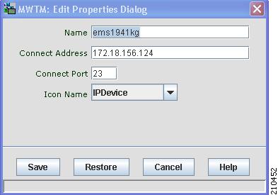
Editing Properties for a RAN-O Backhaul
To edit the properties of a backhaul interface, right-click the backhaul object in the navigation tree or right pane, and choose Edit > Properties in the right-click menu.
The MWTM displays the Edit RAN Backhaul Properties dialog box (Figure 6-3).
Figure 6-3 Edit RAN Backhaul Properties Dialog
The Edit RAN Properties dialog box contains:
Name
Name of the backhaul.
You can use this field to specify a new, more meaningful name for the backhaul.
Remember that:
•
–
–
–
If you enter a name that is longer than 30 characters, or if you enter any other special characters, the MWTM beeps and retains the current name.
Name
(continued)
•
When you click Save, all MWTM windows are updated automatically to reflect the new name.
Threshold Information
Pane that displays three slider bars for controlling the Acceptable, Warning, and Overloaded threshold settings. Left-click the slider and drag it to the desired setting for each threshold. See Threshold Information (RAN-O Only), page 8-42 for descriptions of these thresholds.
Bandwidth Information
Pane that displays:
•
When you change the User Bandwidth, you are changing the scale of the Y axis of the backhaul real-time chart in the Performance tab (see Viewing Backhaul Performance Data, page 8-126). The X and Y values of the data do not change. The threshold ranges resize because they are percentages of User Bandwidth.
The User Bandwidth represents 100% utilization. Data points that are higher than the User Bandwidth will exceed 100% utilization. The Y axis dynamically increases to display all data points.
•
Save
Saves changes that you make to the object information, updates all MWTM windows to reflect your changes, and exits the dialog box.
Restore
Restores changes that you make to the Name, and sets the Threshold Information, and Bandwidth Information fields to the system defaults. The dialog box is left open.
Cancel
Exits the dialog box without saving any changes.
Help
Displays online help for the dialog box.
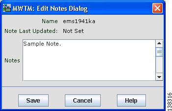
Attaching Notes
You use the MWTM to annotate an object, attaching a descriptive string to it. To attach a note to an object, right-click the object, then choose Edit > Notes. The MWTM displays the Edit Notes dialog box.
Example:
To attach a note to a node, right-click the node in the Node table in the right pane or within a view in the navigation tree, then choose Edit > Notes in the right-click menu.
Figure 6-4 Edit Notes Dialog
The Edit Notes dialog box contains:
Viewing Notes
You use the MWTM to view any notes that are associated with an object. To view a note:
•
•
The MWTM displays the Notes tab for the selected object, which shows:
•
•
Not Setif no notes are associated with the object.•
No Notesif no notes are associated with the object.Example:
To view a note for a node, right-click the node in the Node table in the right pane or within a view in the navigation tree, then choose View > Notes in the right-click menu.
Deleting Objects
After discovery, the objects in your network are known to the MWTM and added to the MWTM database. Physically deleting objects from your network is not the same as deleting them from the MWTM database. These sections describe the differences between deleting objects from your network, the MWTM database, and the MWTM discovery database, and the procedures for doing so:
•
•
Deleting an Object from Your Network
If you physically delete a known object from your network (for example, by powering down a node), it remains in the MWTM database, the MWTM labels it Unknown, and the system administrator is responsible for deleting it from the MWTM database, if you choose to do so.
Note
Deleting an Object from the MWTM Database
Typically, you delete an object from the MWTM database for one of these reasons:
•
•
You are aware of the reason for the state, and you no longer want to see the object in the MWTM displays. For example, the object might be a test lab device, or it could be associated with an object that was removed from the network.
Note
•
If you have physically deleted a known object from your network, and you then delete it from the MWTM, it is no longer in the MWTM database, it does not appear in MWTM windows, and it is not discovered when you run discovery.
If you have not physically deleted a known object from your network, and you delete it from the MWTM, any associated objects are also automatically deleted from the MWTM database (if applicable). However, at the next poll the MWTM finds the object (and any associated objects) and adds it back to the MWTM database, setting the status appropriately. If this happens, do not delete the object again. Instead, set it to Ignored. See Ignoring and Unignoring Objects for more information.
To delete an object from the MWTM database, use one of these procedures:
Note
•
•
The MWTM asks you to confirm the deletion. Click:
•
•
You can also enter the mwtm delete commands from the command line interface to delete one or more objects from the MWTM database. See mwtm delete, page B-18 for more information on the use of this command.
Deleting a Node from the MWTM Discovery Dialog
If you want to completely eliminate a given node from the MWTM database, you can delete it from the MWTM Discovery dialog box, ensuring that the MWTM never even discovers it.
Note
To delete a node from the MWTM Discovery dialog box:
Step 1
Step 2
Step 3
Step 4
The MWTM deletes the nodes from the MWTM database, without asking for confirmation. The MWTM will no longer discover the nodes.
Unmanaging and Managing Nodes or ITP Signaling Points
You use the MWTM to change a node or any associated signaling point to the Unmanaged state. You can also remove the Unmanaged state from these objects.
In some situations, you might not want to a node or signaling point to appear in MWTM windows. However, you might be unable to delete the object from the MWTM database. For example, if:
•
•
In these situations, you can label the object as Unmanaged. When you set a node or signaling point to the Unmanaged state, the MWTM removes the object from the poll list.
Note
To label a node or signaling point Unmanaged:
Step 1
Note
Step 2
Note
You can also remove the Unmanaged status from a node or signaling point, when you are ready to return them to the MWTM poll list. To remove the Unmanaged status from an object:
Step 1
Note
Step 2
Note
Excluding Nodes or ITP Signaling Points from a View
To exclude a node or signaling point from the current view, right-click the node or signaling point in a window, then select Exclude from View in the right-click menu. The MWTM excludes the node or signaling point from the current view. See Creating a New View, page 7-9 for more information about excluding objects from views.
Ignoring and Unignoring Objects
You can instruct the MWTM to ignore an object when it aggregates and displays network data. Setting objects to Ignored prevents known problems from affecting MWTM displays for associated network objects. In effect, you are preventing a known problem from distracting you from other, more urgent network problems.
Example:
You can set a node to Ignored before shutting down the node for maintenance.
Note
Also, if you set an object to Ignored, make a note of the change, and remember to reset the object when the problem is corrected or the maintenance is complete.•
Right-click the object, then select Ignore from the menu
or
In the object window in the right pane, check the Ignored check box.
•
•
•