-
Cisco IP Solution Center Traffic Engineering Management User Guide, 4.1
-
Document Type Definition (DTD) File
-
Index
-
About This Guide
-
Introduction
-
Setting Up the Service
-
TE Network Discovery
-
TE Resource Management
-
Basic Tunnel Management
-
Primary Tunnel Management
-
Protection Planning
-
Traffic Admission
-
Administration
-
Task Monitoring
-
TE Topology
-
Traffic Engineering Management GUI
-
Managing Service Requests
-
Warnings and Violations
-
 Feedback
Table Of Contents
Protection Planning
This chapter describes the process of creating and managing the protection of network elements using automated protection tools. See "Basic Tunnel Management" for a description of the process using the basic tools.
This chapter includes the following sections:
Overview
The purpose of protection planning is to protect selected elements in the network (links, routers, or SRLGs) against failure.
The first step is to identify the elements that must be protected and then invoke the protection tools to compute the protected tunnels. From the computation, the system responds for each element with either a set of tunnels that protect the element or a set of violations and warnings that help the user to determine why it could not be protected.
For successfully protected elements the tunnels can be deployed on the network. For elements that could not be protected, the protection is either ignored or the constraints are altered on the protection case. More specifically, this can involve changing the TE bandwidth settings of the links associated to the element and then rerunning the protection computation on the altered network.
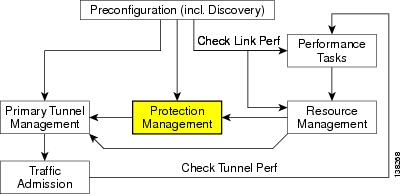
An overview of the protection management processes is provided in Figure 7-1.
Figure 7-1 Protection Management Processes
SRLG Operations
It is not uncommon for links to have identical physical characteristics, such as being physically located in the same conduit, or being connected to the same hardware. As a result, they could fail as a group during a single failure event. A Shared-Risk Link Group (SRLG) addesses this problem by identifying links that could fail together.
After SRLG modifications (create, edit, delete), use the protection planning functions in the TE Protection Management window to ensure that adequate protection is available on the network.
Note
If you include a non-POS interface of an IOS-XR device in an SRLG, the SRLG cannot be protected.
Create SRLG
Creating an SRLG is only necessary if a shared risk link group has been identified and it must be protected.
To create an SRLG, use the following steps:
Step 1
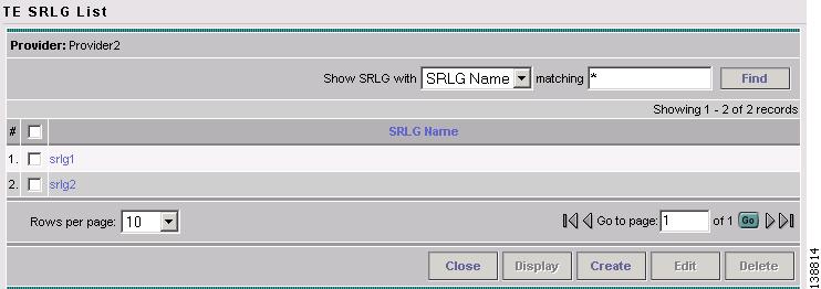
Step 2
Figure 7-2 TE SRLG List
For an explanation of the various window elements, see Create/Edit TE SRLG.
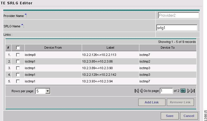
Step 3
Figure 7-3 TE SRLG Editor
For an explanation of the various window elements , see Create/Edit TE SRLG.
Step 4
Step 5
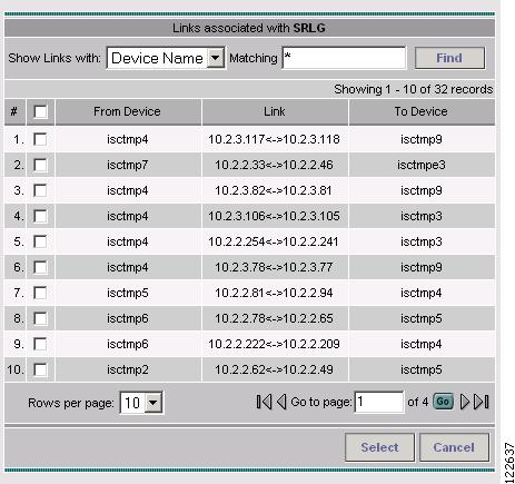
Figure 7-4 Links associated with SRLG
For an explanation of the various window elements , see Create/Edit TE SRLG.
Step 6
Step 7
Edit SRLG
To edit an SRLG, use the following steps:
Step 1
Step 2
Step 3
Step 4
Step 5
Delete SRLG
To delete an SRLG, use the following steps:
Step 1
Step 2
Step 3
Step 4
Configure Element Protection
Before a protection computation can be performed, it is necessary to configure the network element protection.
To do so, use the following steps:
Step 1
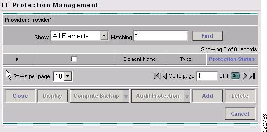
The TE Protection Management window in Figure 7-5 appears.
Figure 7-5 TE Protection Management
For an explanation of the various window elements, see Protection Management.
Step 2
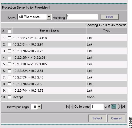
In the TE Protection Management window, click Add to add a protection element (link, node, or SRLG). The Select Protection Elements window in Figure 7-6 appears.
Note
Links that are connected to non-Cisco devices cannot be protected and will, therefore, not show in the Select protection elements window. Likewise, non-Cisco devices and SRLGs that contain links to non-Cisco devices cannot be protected and are excluded from the selection.
Figure 7-6 Select Protection Elements
For an explanation of the various window elements, see Protection Management.
Step 3
Next, decide which protection tools should be applied.
Protection Tools
Relying on manual creation of backup tunnels as described in "Basic Tunnel Management" has its limitations, not just for larger and more complicated networks.
The protection tools available in ISC TEM provide a number of tools that automatically compute and verify protection of specified network elements.
Note
Compute Backup
Compute Backup is used to let ISC TEM automatically compute the necessary backup tunnels to protect specified network elements. The manual process is described in "Basic Tunnel Management."
To run Compute Backup, use the following steps:
Step 1
Step 2
Step 3
Click Compute Backup and select one of the following:
•
•
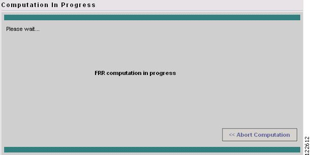
The Computation In Progress window shown in Figure 7-7 appears.
Figure 7-7 FRR Computation In Progress - Compute Backup
To abort the computation and return to the previous window, click << Abort Computation.
Step 4
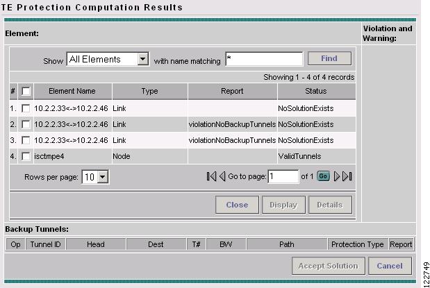
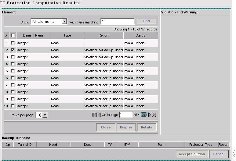
Figure 7-8 TE Protection Computation Results
For an explanation of the various window elements, see Compute Backup.
Note
Step 5
For a description of warnings and violations, see "Warnings and Violations."
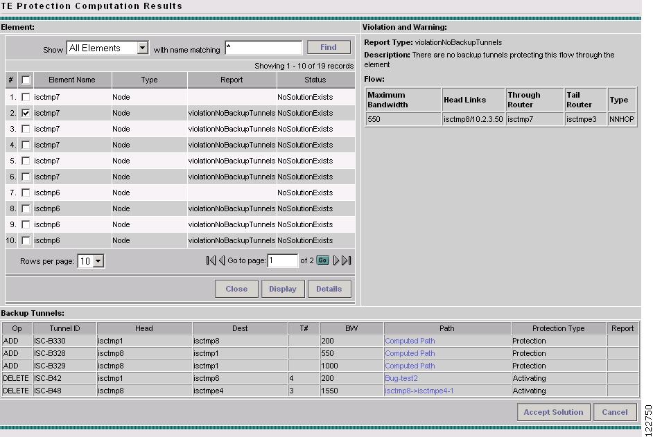
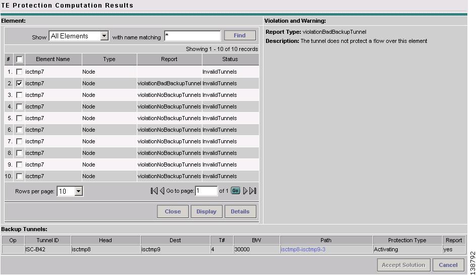
Figure 7-9 TE Protection Computation Results with Backup Tunnels
For an explanation of the various window elements, see Compute Backup.
The Backup Tunnel table displays which new protection tunnels are required and any existing tunnels that should be kept or deleted for each element.
Step 6
Figure 7-10 TE Protection SR - Computed Path
For an explanation of the various window elements, see Create TE Backup Tunnel.
Optionally, you can make tunnel changes here and then run Audit SR to ensure that you have the desired level of protection before you deploy (see Audit SR).
Step 7
Note
Note
Step 8
For more information on working with service requests, see "Managing Service Requests."
If the SR does not go to the Deployed state, go to the Task Logs screen to see the deployment log (Monitoring > Task Manager > Logs) as described in SR Deployment Logs.
Audit Protection
As opposed to the Compute Backup tool described on page 7, Audit Protection does not attempt to create a backup solution. It seeks to verify protection of specified network elements with the current set of backup tunnels and reports any warnings or violations that are discovered. It is recommended that any time a change has been committed on the TE topology such as resources on TE links or SRLG memebership, a protection audit be run to verify the protection status on all elements.
The computation will display the same computation result page as for Compute Backup. When you return from computation result page, the Protection Status column in the TE Protection Management window is updated to show the level of protection for each element.
This section describes the necessary steps to perform Audit Protection on one or more network elements.
To run Audit Protection, use the following steps:
Step 1
The TE Protection Management window in Figure 7-5 appears.
Step 2
Click Audit Protection and select one of the following:
•
•
The Computation In Progress window shown in Figure 7-7 appears.
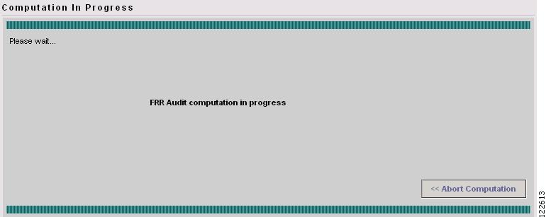
Figure 7-11 FRR Audit Computation in Progress - Audit Protection
To abort the computation and return to the previous window, click << Abort Computation.
The TE Protection Computation Results window in Figure 7-12 appears.
Figure 7-12 TE Protection Computation Results
For an explanation of the various window elements, see Compute Backup.
Note
Step 3
The TE Protection Computation Results window in Figure 7-13 appears.
Figure 7-13 TE Protection Computation Results with Backup Tunnels
For an explanation of the various window elements, see Compute Backup.
Step 4
Tunnels associated with a warning or violation are flagged in the Report column in the Backup Tunnels table in the bottom pane.
The Accept Solution button is greyed out because the audit does not provide a solution but rather an evaluation.
For a description of warnings and violations, see "Warnings and Violations."
Step 5
Audit SR
Audit SR audits protection of all elements in the TE Protection Management window against backup tunnels in the TE Protection SR window.
This feature can be used to audit the protection for manually added, modified, and deleted tunnels in the TE Protection SR window before deploying them.
To audit a TE backup tunnel SR, use the following steps:
Step 1
Step 2
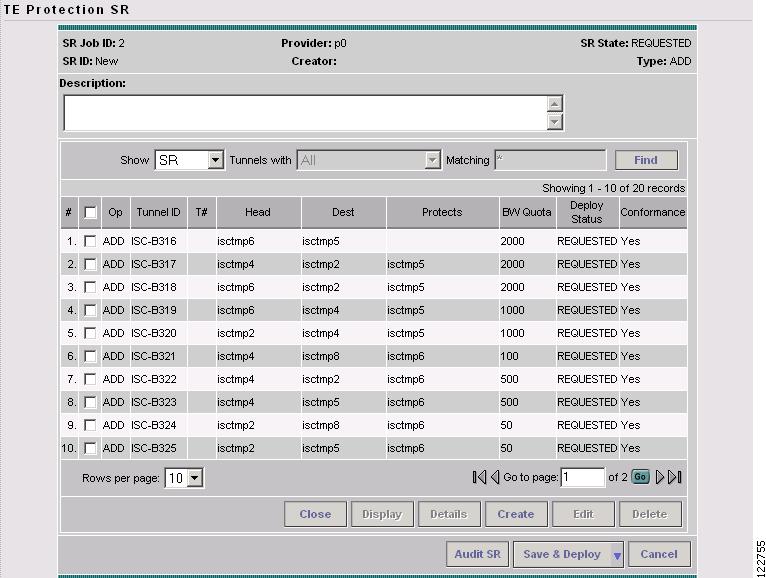
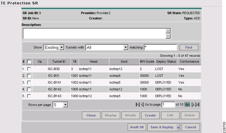
Figure 7-14 TE Protection SR
For an explanation of the various window elements, see Create TE Backup Tunnel.
Step 3
Note
The FRR Audit process begins and the TE Protection Computation Results window in Figure 7-12 appears.
See Audit Protection for a description of the rest of the process. Detail and report windows are identical in these two processes.