-
Cisco IP Solution Center Traffic Engineering Management User Guide, 4.1
-
Document Type Definition (DTD) File
-
Index
-
About This Guide
-
Introduction
-
Setting Up the Service
-
TE Network Discovery
-
TE Resource Management
-
Basic Tunnel Management
-
Primary Tunnel Management
-
Protection Planning
-
Traffic Admission
-
Administration
-
Task Monitoring
-
TE Topology
-
Traffic Engineering Management GUI
-
Managing Service Requests
-
Warnings and Violations
-
 Feedback
Table Of Contents
Feature-Specific Prerequisites and Limitations
Preconfiguration Process Overview
ISC TEM Setup and Installation
Editing DCPL Properties (Optional)
Getting Started
This chapter describes the installation procedure for ISC TEM. The general installation procedure for Cisco IP Solutions Center (ISC) is described in Cisco IP Solution Center Installation Guide, 4.1.
This chapter includes the following sections:
•
Prerequisites and Limitations
–
–
•
•
–
–
Prerequisites and Limitations
The current release of ISC TEM involves certain prerequisites and limitations, which are described in this section.
See Cisco IP Solution Center Installation Guide, 4.1 for general system recommendations.
General Limitations
Concurrent use of the same installation is not supported. Let issued service requests finish deployment before issuing other service requests to avoid conflicts. This is described in more detail in the tunnel provisioning chapters.
The concurrency limitation also implies that opening multiple browsers displaying a single ISC installation is not recommended.
ISC TEM only supports MPLS-TE topology with point-to-point links.
Feature-Specific Prerequisites and Limitations
Some features might only be available with a particular license. In addition, the number of nodes provided by the license limits the size of the network. For more information, see Licensing Schemes.
A number of specific requirements are associated with the TE Discovery task. These are described in TE Discovery Prerequisites.
In the Planning portion of the current implementation of ISC TEM, concurrent use is not recommended as users working simultaneously risk being unable to commit their changes.
JRE version 1.4.2_04 or higher should be installed on the client computer, and if the user does not already have Java installed, they can use the links on the Topology Tool page to install the version that is bundled with ISC.
Non-POS interfaces cannot be protected on IOS-XR devices.
For users who have a repository that predates the ISC 4.1 release and has been upgraded to a 4.1 repository, you need to run a TE Discovery task to collect software version information from the devices before deploying service requests.
Non-Cisco Devices and ISC TEM
ISC TEM does not manage non-Cisco devices and ISC cannot be used to provision them.
ISC will, however, discover non-Cisco devices and store them in the repository. Tunnels can be run through these devices, the bandwidth consumed can be accounted for, but the devices are not otherwise managed by ISC. TE tunnels originating from non-Cisco devices will not be discovered.
Sorting can be performed on different attributes in various parts of the ISC TEM GUI. However, due to the added support for non-Cisco devices, sorting cannot be performed on Device Name and MPLS TE ID in the TE Nodes List window.
Supported Platforms
For supported devices and IOS platforms, see Cisco IP Solution Center Installation Guide, 4.1.
Preconfiguration Process Overview
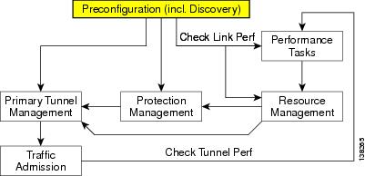
The preconfiguration process sets up key parameters that enable the system to collect TE network information and subsequently deploy TE configurations on the chosen network.
An overview of the preconfiguration process is provided in Figure 2-1.
Figure 2-1 Preconfiguration Process
Before commencing the preconfiguration process, MPLS-TE needs to be enabled on the network devices by making sure that the IP addresses used as devices' TE IDs are accessible from the management station (this step is not supported by ISC TEM).
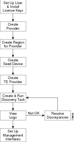
The preconfiguration process includes the following steps:
Step 1
Step 2
Step 3
Step 4
Step 5
Step 6
Step 7
Note
ISC TEM Setup and Installation
Before setting up ISC TEM, the ISC software must be installed. To do so, see Cisco IP Solution Center Installation Guide, 4.1.
To set up a new ISC TEM user, one or more users with a TE role must be created. For step by step instructions, see Cisco IP Solution Center Infrastructure Reference, 4.1.
Installing an ISC TEM License
Cisco IP Solution Center Traffic Engineering Management (ISC TEM) offers the license structure described in "Introduction to ISC TEM."
For an explanation of license keys in ISC, see Cisco IP Solution Center Infrastructure Reference, 4.1.
To install a TE license, use the following steps:
Step 1
•
•
Step 2
Step 3
Step 4
Step 5
Step 6
Step 7
Step 8
Step 9
•
•
•
Repeat the procedure for each license key.
Typing in all three license keys is the only valid installation.
Step 10
Step 11
You are now ready to start using ISC TEM.
Note
Editing DCPL Properties (Optional)
The ISC Dynamic Component Properties Library (DCPL) includes a wide variety of properties that are accessible from the GUI, some of which can be modified.
The various DCPL properties in ISC, including those pertaining to ISC TEM, and the process for editing these properties are described in Cisco IP Solution Center Infrastructure Reference, 4.1.
Warning
In the ISC GUI, the DCPL properties are found in Administration > Control Center > Hosts. Select a check box for a specific host and click the Config button.
The DCPL properties pertaining to ISC TEM are found in the following folders:
•
•
•
Creating a TE Provider
After a provider and a region for that provider have been set up (see Cisco IP Solution Center Infrastructure Reference, 4.1), create a TE provider using the following steps:
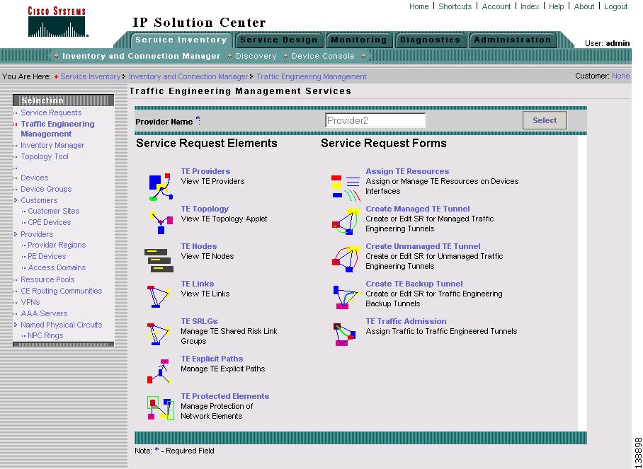
Step 1
The Traffic Engineering Management Services window shown in Figure 2-2 appears.
Figure 2-2 Traffic Engineering Management Services
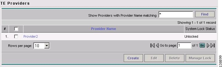
Step 2
The TE Providers window shown in Figure 2-3 appears.
Figure 2-3 TE Providers
For an explanation of the various window elements, see the "TE Providers" section.
Step 3
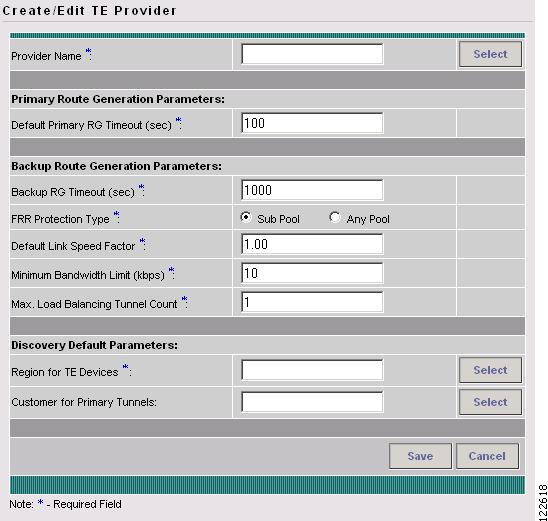
The Create / Edit TE Provider window shown in Figure 2-4 appears.
Figure 2-4 Create/Edit TE Provider
For an explanation of the various window elements, see Create/Edit TE Provider.
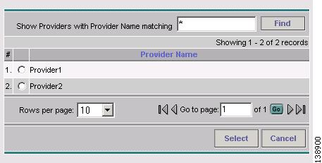
To select a provider name, click the Select button next to the Provider Name field. The Select Provider window shown in Figure 2-5 appears.
Step 4
When the FRR protection type is equal to Sub Pool, the backup tunnels generated by the tool will protect only the sub pool primary tunnels. When it is equal to Any Pool, the backup tunnels generated by the tool will protect both sub pool and global pool primary tunnels.
For more information on Fast Re-Route (FRR) protection pools, see Bandwidth Pools.
Figure 2-5 Select Provider for Create TE Provider
Step 5
Step 6
The selected provider name is displayed in the Provider Name field.
Step 7
Step 8
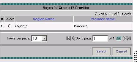
Figure 2-6 Select Region for Create TE Provider
Step 9
Step 10
The selected region name is displayed in the Region for TE Devices field.
Step 11
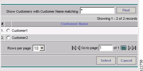
Figure 2-7 Select Customer for Create TE Provider
Step 12
Step 13
The selected customer name is displayed in the Customer for Primary Tunnels field of the Create/Edit TE Provider window.
Step 14
The created TE provider appears in the TE Provider window and can now be used to perform TE discovery and other TE functions.
To switch between TE providers, go to the top of the Traffic Engineering Management Services window (Figure 2-2) and click the Select button for the Provider Name field.