-
Cisco 3800 Series Hardware Installation
-
Cisco Access Router USB Flash Module and USB eToken Hardware Installation Guide
-
Introduction to Cisco 3800 Series Routers Hardware Documentation
-
Overview of Cisco 3800 Series Routers
-
Preinstallation Requirements and Planning for Cisco 3800 Series Routers
-
Installing Cisco 3800 Series Routers in an Equipment Rack
-
Connecting Cables to Cisco 3800 Series Routers
-
Powering Up Cisco 3800 Series Routers
-
Troubleshooting Cisco 3800 Series Routers
-
Installing Network Modules in Cisco 3800 Series Routers
-
Installing Interface Cards in Cisco 3800 Series Routers
-
Installing SFP Modules in Cisco 3800 Series Routers
-
Installing CompactFlash Memory Cards in Cisco 3800 Series Routers
-
Installing and Upgrading Internal Components in Cisco 3800 Series Routers
-
 Feedback
Table Of Contents
Troubleshooting Cisco 3800 Series Routers
Troubleshooting the Power and Cooling Systems
Environmental Reporting Features
Troubleshooting Modules, Cables, and Connections
Cisco 3845 Router Error Messages
Troubleshooting Cisco 3800 Series Routers
Your Cisco 3800 series integrated services router goes through extensive testing and burn-in before leaving the factory. If you encounter problems, use this document to help isolate problems or to eliminate the router as the source of the problem.
This document contains the following sections:
•
LEDs
Note
If you cannot find the source of the problem, contact a customer service representative. For information about obtaining technical support, see the "Obtaining Technical Assistance" section on page 12 of "Introduction to Cisco 3800 Series Routers Hardware Documentation." Before you call, have the following information ready:
•
•
•
•
•
•
Solving Problems
The key to solving problems is to isolate the problem to a specific subsystem by comparing what the router is doing to what it should be doing.
The LEDs on the front and rear panel of the router enable you to determine router performance and operation. LEDs are described in the "LEDs" section.
When solving problems, consider the following subsystems:
•
•
•
Troubleshooting the Power and Cooling Systems
Both the system power LED and the fans can help you troubleshoot a power problem. Check the following items.
Note
Normal Indications
With the power switch on, normal indications are:
•
•
•
Fault Indications
Check the following symptoms to locate or eliminate faults in the power and cooling systems:
•
–
–
–
•
–
–
•
–
–
•
–
–
•
–
–
–
•
–
–
Environmental Reporting Features
If the router is operating at an abnormally high temperature, the following message is displayed on the console screen:
System detected OVERTEMPERATURE condition. Please resolve cooling problem immediately!Some causes of abnormally high router temperature are:
•
•
•
Take steps to correct the problem. See also the "Site Environment" section on page 4 and the "Equipment Racks" section on page 5 of "Preinstallation Requirements and Planning for Cisco 3800 Series Routers."
Troubleshooting Modules, Cables, and Connections
Network problems can be caused by a module; cables or cable connections; or external devices such as a modem, transceiver, hub, wall jack, WAN interface, or terminal. Check for the following symptoms to help isolate the problem:
•
–
–
–
•
–
–
–
•
–
–
•
–
–
- The data rate matches the one configured for the router (9600 bps is the default)
- 8 data bits
- No parity
- 1 stop bit
•
–
•
–
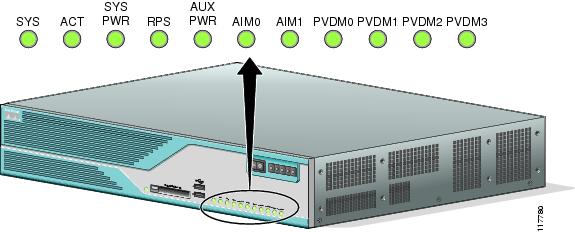
LEDs
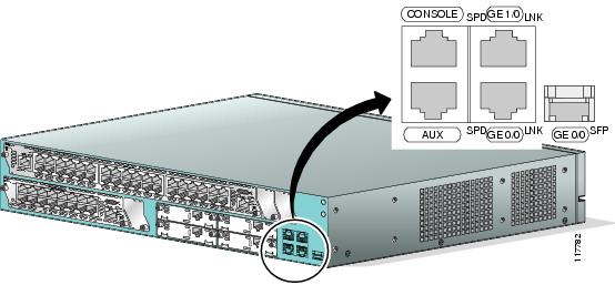
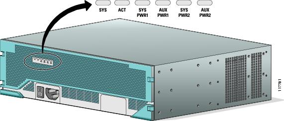
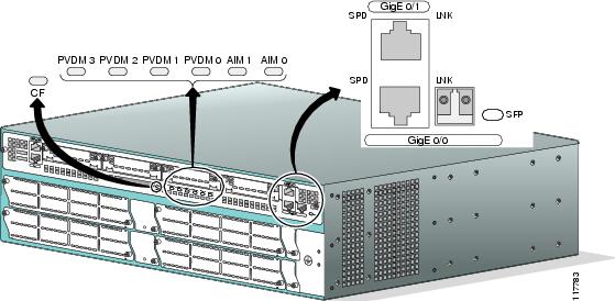
LEDs enable you to determine router performance and operation. Figure 26 and Figure 27 show the LEDs on the Cisco 3825 router. Figure 28 and Figure 29 show the LEDs on the Cisco 3845 router. Each power supply in a Cisco 3845 router also has its own LED.
For an explanation of these LEDs, see Table 5.
Figure 26 Cisco 3825 Front-Panel LEDs
Figure 27 Cisco 3825 Rear-Panel LEDs
Figure 28 Cisco 3845 Front-Panel LEDs
Figure 29 Cisco 3845 Router Rear-Panel LEDs
The show environment Command
The show environment command can help you monitor and troubleshoot router power and ventilation status.
This is an example of the output of the show environment command for a Cisco 3825 router with an AC power supply and no Redundant Power System:
Router# show environmentRedundant Power System is not present.SYS PS1 is present.Type: ACAUX (-48V) PS1 is absent.Fan 1 NormalFan 2 NormalFan 3 NormalFan Speed is NormalAlert settings:Intake temperature warning: Enabled, Threshold: 50Core temperature warning: Enabled, Threshold: 70 (CPU: 95)Board Temperature: NormalInternal-ambient temperature = 29, NormalCPU temperature = 46, NormalIntake temperature = 31, NormalVoltage 1(3300) is Normal, Current voltage = 3316 mVVoltage 2(5150) is Normal, Current voltage = 5210 mVVoltage 3(2500) is Normal, Current voltage = 2525 mVVoltage 4(1200) is Normal, Current voltage = 1191 mVThis is an example of the output of the show environment command for a Cisco 3845 router that has one AC power supply with IP phone power output installed:
Router# show environmentSYS PS1 is presentFan status: NormalInput Voltage status: NormalDC Output Voltage status: NormalType: ACThermal status: NormalSYS PS2 is absentAUX (-48V) PS1 is presentAUX (-48V) PS2 is absentFan 1 NormalFan 2 NormalFan 3 NormalFan Speed is NormalAlert settings:Intake temperature warning: Enabled, Threshold: 50Core temperature warning: Enabled, Threshold: 70 (CPU: 90)Board Temperature: NormalInternal-ambient temperature = 31, NormalCPU temperature = 50, NormalIntake temperature = 25, NormalBackplane temperature = 24, NormalVoltage 1(3300) is Normal, Current voltage = 3284 mVVoltage 2(5150) is Normal, Current voltage = 5210 mVVoltage 3(2500) is Normal, Current voltage = 2549 mVVoltage 4(1200) is Normal, Current voltage = 1215 mVError Messages
This section describes error messages that may appear on an external console screen. (For more information about consoles, see the "Connecting a Console or Modem" section on page 29 of "Connecting Cables to Cisco 3800 Series Routers.")
Cisco IOS software checks the system once every 30 seconds. If an error still exists, the error message is displayed again; if the error has cleared, a recovery message is displayed.
Error Message    System detected OVERTEMPERATURE condition. Please resolve cooling
problem immediately!
Explanation The router is operating at a temperature higher than the user-set threshold, possibly caused by fan failure, air-conditioning failure in the room, or air blockage to cooling vents.
Recommended Action Make sure that the ambient room temperature does not exceed 40 degrees C and that airflow to the router is not blocked. See the "Site Environment" section on page 4 and the "Equipment Racks" section on page 5 of "Preinstallation Requirements and Planning for Cisco 3800 Series Routers."
If this condition persists, the power-supply thermal monitor automatically shuts down the router. Call your Cisco technical support representative for help, if necessary.
Error Message Fan 1|2|3 had a rotation error reported.Explanation The specified fan is not rotating at the desired speed.
Recommended Action If this error is detected, the router system software automatically increases the fan speed to high. If the rotation error disappears, fan speed is kept at high. If this error appears repeatedly, there is something wrong with the fan. The error will reappear until action is taken.
Error Message    Voltage 1|2|3|4 (3300 mv|5150 mv|2500 mv|1200 mv) has exceeded
recommended operating limits.
Explanation One of the internal voltage outputs is outside its operating limits.
Recommended Action System failure. See the "Obtaining Technical Assistance" section on page 12 of "Introduction to Cisco 3800 Series Routers Hardware Documentation" for information about customer service.
Cisco 3845 Router Error Messages
The Cisco 3845 router supports two internal power supplies and returns the following error messages for them.
Error Message System detected SYS PS 1|2 input voltage fail condition.Explanation Power to the indicated power supply has failed.
Recommended Action Check the input power source and power cable.
Error Message System detected SYS PS 1|2 output voltage fail condition.Explanation The indicated power supply has failed.
Recommended Action Replace the power supply. See "Installing and Upgrading Internal Components in Cisco 3800 Series Routers."
Error Message System detected AUX (-48V) PS 1|2 fail condition.Explanation The indicated AC power supply with IP phone power output has failed.
Recommended Action Replace the power supply. See "Installing and Upgrading Internal Components in Cisco 3800 Series Routers."
Error Message    System detected thermal warning on SYS PS 1|2. System is close to auto
shutdown limit.
Explanation The power supply is operating at an abnormally high temperature.
Recommended Action Make sure that the ambient room temperature does not exceed 40 degrees C and that air flow to the router is not blocked. See the "Site Environment" section on page 4 and the "Equipment Racks" section on page 5 of "Preinstallation Requirements and Planning for Cisco 3800 Series Routers."
The power supply fan may have failed or be about to fail. Replace the power supply. See "Installing and Upgrading Internal Components in Cisco 3800 Series Routers."
If this condition persists, the power-supply thermal monitor automatically shuts down the router. Call your Cisco technical support representative for help, if necessary.
Error Message System detected SYS PS 1|2 fan fail condition.Explanation The fan on the indicated power supply has failed.
Recommended Action Replace the power supply. See "Installing and Upgrading Internal Components in Cisco 3800 Series Routers."
Error Message    There is more than one failure with power system 1|2 or this power
system has been turned off.
Explanation Multiple failures have occurred in the indicated power supply. This message can also appear if you have installed two power supplies in a Cisco 3845 router, but only one is powered on.
Recommended Action If the power supply is turned off, turn it on. If it has failed, replace it. See "Installing and Upgrading Internal Components in Cisco 3800 Series Routers."
Jumper Settings
If a ROM monitor failure occurs, you may need to change a jumper setting on the motherboard so the router can boot for troubleshooting. Procedures for accessing the motherboard are described and jumper locations are shown in "Installing and Upgrading Internal Components in Cisco 3800 Series Routers." You may need to set one of the following jumpers:
•
Change this setting if the console displays garbage characters. The jumper forces the data rate to a known good value.
•
Change this setting if the router consistently hangs or crashes after a ROM monitor upgrade.
•
If you change either of the first two settings as shown, the router stays in the new configuration during subsequent power cycles and the jumper can be removed.
Note
Change these settings only after consulting with your service representative or Cisco technical support.
Recovering a Lost Password
You can recover a lost enable password, but an enable secret password is encrypted and is not recoverable. If you lose an enable secret password configured on your router, you can replace it with a new enable secret password.
For password recovery and replacement procedures, see http://www.cisco.com/en/US/products/hw/routers/ps274/products_password_recovery09186a0080094774.shtml.
More Troubleshooting Help
For information about obtaining technical support, see the "Obtaining Technical Assistance" section on page 12 of "Introduction to Cisco 3800 Series Routers Hardware Documentation."