-
Cisco 3800 Series Hardware Installation
-
Cisco Access Router USB Flash Module and USB eToken Hardware Installation Guide
-
Introduction to Cisco 3800 Series Routers Hardware Documentation
-
Overview of Cisco 3800 Series Routers
-
Preinstallation Requirements and Planning for Cisco 3800 Series Routers
-
Installing Cisco 3800 Series Routers in an Equipment Rack
-
Connecting Cables to Cisco 3800 Series Routers
-
Powering Up Cisco 3800 Series Routers
-
Troubleshooting Cisco 3800 Series Routers
-
Installing Network Modules in Cisco 3800 Series Routers
-
Installing Interface Cards in Cisco 3800 Series Routers
-
Installing SFP Modules in Cisco 3800 Series Routers
-
Installing CompactFlash Memory Cards in Cisco 3800 Series Routers
-
Installing and Upgrading Internal Components in Cisco 3800 Series Routers
-
 Feedback
Table Of Contents
Connecting Cables to Cisco 3800 Series Routers
Connecting Routers to AC Power
Connecting Routers to DC Power
DC Wiring Requirements for Cisco 3800 Series Routers
Dual DC Power Supply Configuration in Cisco 3825 and Cisco 3825-NOVPN Routers
Connecting Routers to Backup Power
Connecting WAN, LAN, and Voice Cables
Connecting a Console to the Console Port
Connecting a Modem to the Auxiliary Port
Connecting Cables to Cisco 3800 Series Routers
This document describes how to connect your Cisco 3800 series integrated services router to a power source and to networks and external devices. It includes the following sections:
•
Connecting WAN, LAN, and Voice Cables
•
Warning
Warning
Warning
Power Connections
This section explains how to connect AC or DC power inputs to Cisco 3825, Cisco 3825-NOVPN, Cisco 3845, and Cisco3845-NOVPN routers. It covers the following topics:
•
•
•
Warning
Note
Connecting Routers to AC Power
If your router uses AC power, connect it to a 15 A, 120 VAC (or 10 A, 240 VAC) circuit with overcurrent protection. If backup power is required, see the "Connecting Routers to Backup Power" section.
Note
Warning
Warning
The following warning applies to both AC power supplies and AC power supplies with IP phone power in the Cisco 3825, Cisco 3825-NOVPN, Cisco 3845 and Cisco 3845-NOVPN routers:
Warning
120 VAC, 45 A (240 VAC, 30 A). Statement 1005
Warning
120 VAC, 30 A (240 VAC, 20 A). Statement 1005
Connecting Routers to DC Power
If your router has a DC-input power supply, follow the directions in this section for proper wiring. If backup power is required, see the "Connecting Routers to Backup Power" section.
DC Wiring Requirements for Cisco 3800 Series Routers
Warning
Warning
The following warning applies to the Cisco 3825 and Cisco 3825-NOVPN routers only:
Warning
60 VDC, 20 A. Statement 1005
The following warning applies to the Cisco 3845 and Cisco 3845-NOVPN routers only:
Warning
60 VDC, 30 A. Statement 1005
Table 2 and Table 3 summarize DC wiring requirements for all Cisco 3825 and Cisco 3845 routers.
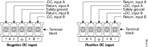
For a Cisco 3845 and Cisco 3845-NOVPN routers, the safety ground wire connection must be at the same potential as the 0 V (return) connection.
Table 2 DC Wiring Requirements for Cisco 3825 and Cisco 3825-NOVPN Routers
Wire Size24-36 VDC, 12 A, positive or negative, single or dual source
AWG 14 (2.0 mm2)
AWG 14 (2.0 mm2), minimum
Amp/Tyco No. 32957 or equivalent
20 A
36-60 VDC, 8 A, positive or negative, single or dual source
1 The input voltage tolerance limits for DC power are 18 and 72 VDC.
Table 3 DC Wiring Requirements for Cisco 3845 and Cisco 3845-NOVPN Routers
Wire Size
Wire Size24-36 V, 19 A, positive or negative, single or dual source
AWG 12
(3.0 mm2)AWG 12 (3.0 mm2) minimum
Amp/Tyco No. 34852 or equivalent
30 A
36-60 V, 13 A, positive or negative, single or dual source
AWG 12 or 14
(3.0 or 2.0 mm2)AWG 12 (3.0 mm2) minimum
AWG 12: Amp/Tyco No. 34852 or equivalent
AWG 14: Amp/Tyco No. 32957 or equivalent
20-30 A
1 The input voltage tolerance limits for DC power are 18 and 72 VDC.
DC Input Wiring Procedure
To connect the router to a DC power source, follow these steps:
Step 1
Warning
Tip
Warning
Step 2
Step 3
Step 4
Step 5
Warning
Warning
Caution
(1.1 ± 0.05 N-m).
Figure 12 DC Power Connections for Cisco 3825 and 3825-NOVPN Routers
Figure 13 DC Power Connections for the Cisco 3845 and 3845-NOVPN Routers
Step 6
Warning
Step 7
Step 8
Step 9
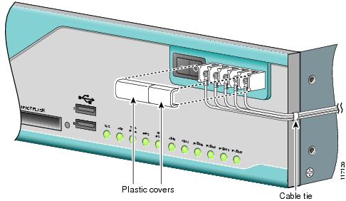
Figure 14 DC Wire Routing and Attachment for Cisco 3825 and 3825-NOVPN Router
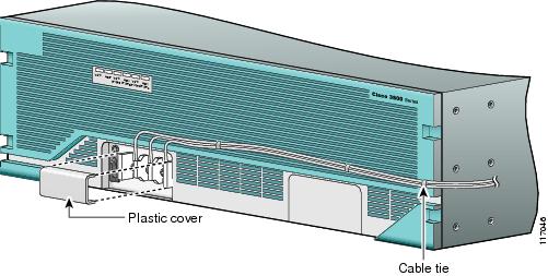
Figure 15 DC Wire Routing and Attachment for Cisco 3845 and 3845-NOVPN Router
Dual DC Power Supply Configuration in Cisco 3825 and Cisco 3825-NOVPN Routers
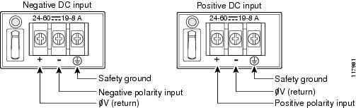
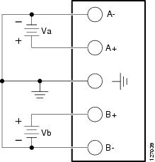
You can connect a single DC power source to either the A input or the B input. If there are dual power sources, connect one source to the A input and one source to the B input. Both sources must have the same polarity (with respect to ground) and voltage (within 0.25 V). Do not connect -DC-grounded and +DC-grounded dual sources to Cisco 3825 and Cisco 3825-NOVPN routers.
Caution
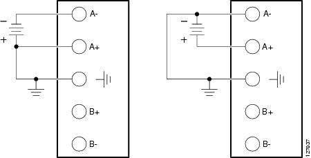
In Figure 16, either the positive source terminal or the negative source terminal is tied to ground.
Figure 16 Connecting to One Source Only—Source A or Source B
In Figure 17, source A and source B share common negative terminal connections.
Figure 17 Connecting Source A and Source B with Common Negative Terminals
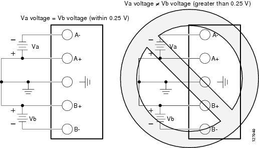
In Figure 18, source A and source B share common positive terminal connections. This configuration is allowed only if Va equals Vb (within 0.25 V).
Caution
Note
Figure 18 Connecting Source A and Source B with Common Positive Terminals
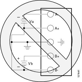
In Figure 19, source A and source B are wired with opposite polarity grounds. Do not use this configuration.
Figure 19 Source A and Source B Wired with Opposite-Polarity Grounds
Connecting Routers to Backup Power
The Cisco 3845 and Cisco 3845-NOVPN routers accommodate two hot-swappable power supplies in bays at the front of the router. A single power supply meets router requirements. The second power supply provides redundancy, load sharing, and increased router availability. Either power supply can be removed without affecting router operation. Any combination of two power supplies is permitted.
For instructions for installing a second power supply in a Cisco 3845 and Cisco 3845-NOVPN routers, see the "Installing and Upgrading Internal Components in Cisco 3800 Series Routers" section.
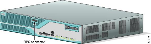
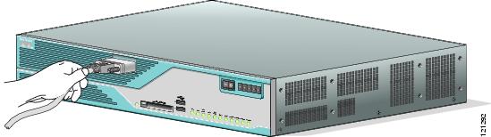
The Cisco 3825 and Cisco 3825-NOVPN router has one internal power supply and provides a connector to an optional Cisco Redundant Power System (RPS) external backup source. Figure 20 and Figure 21 illustrate this connection. Use a flat-blade screwdriver to pry off the door over the RPS connector before connecting the cable. See the Cisco RPS-675 Hardware Installation Guide for complete RPS power connection instructions.
Caution
active mode.
Figure 20 RPS Connector on Cisco 3825 and 3825-NOVPN Router
Figure 21 Connecting RPS to Cisco 3825 and 3825-NOVPN Router
Connecting WAN, LAN, and Voice Cables
This section describes how to connect WAN, LAN, and voice interface cables to your Cisco 3800 series integrated services router.
One Ethernet cable is provided with the router for a Gigabit Ethernet connection. These ports use Category 5, 5e, or 6 UTP 1000BASE-T cable. Additional cables and transceivers can be ordered from Cisco. For ordering information, see the Cisco Product Catalog at http://www.cisco.com/en/US/partner/products/index.html.
Connect each WAN, LAN, or voice cable to the appropriate connector on the router or on a network module or interface card, following these precautions:
•
•
•
•
Cable connections to network modules and interface cards are described in detail in the following documents:
•
•
For cable pinouts, see the Cisco Modular Access Router Cable Specifications document.
Warning
Warning
Warning
Warning
Connecting a Console or Modem
Cisco 3800 series routers provide EIA/TIA-232 asynchronous serial console and auxiliary ports. These ports provide administrative access to the router either locally, using an ASCII terminal or PC running HyperTerminal or similar terminal emulation software connected to the console port, or remotely, using a modem connected to the auxiliary port.
The principal difference between the console and auxiliary ports is that the auxiliary port supports hardware flow control, but the console port does not. Flow control paces the transmission of data between a sending device and a receiving device, ensuring that the receiving device can absorb the data sent to it before the sending device sends more. When the buffers on the receiving device are full, a message is sent to the sending device to suspend transmission until the data in the buffers has been processed.
Because the auxiliary port supports flow control, it is best suited for use with the high-speed transmissions of a modem. Terminals send data at slower speeds than modems; therefore, the console port is best suited for use with terminals.
Cisco provides the following cables and adapters for connecting the router to a console or modem:
•
•
This section describes how to connect a console to the console port and how to connect a modem to the auxiliary port.
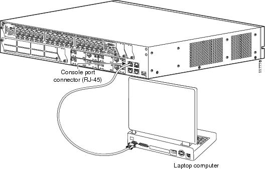
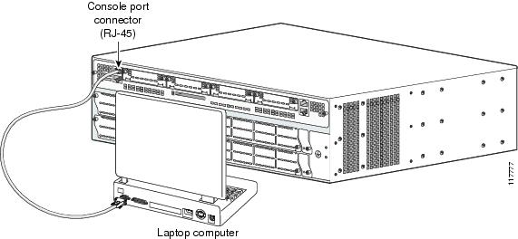
Connecting a Console to the Console Port
To connect a console (ASCII terminal or a PC running HyperTerminal or similar terminal emulation software) to the console port on the router, follow these steps:
Step 1
For information about cable pinouts, see the Cisco Modular Access Router Cable Specifications document.
Note
Step 2
Note
Figure 22 Connecting a Computer to the Cisco 3825 and 3825-NOVPN Router Console Port
Figure 23 Connecting a Computer to the Cisco 3845 and 3845-NOVPN Router Console Port
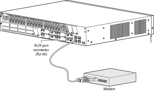
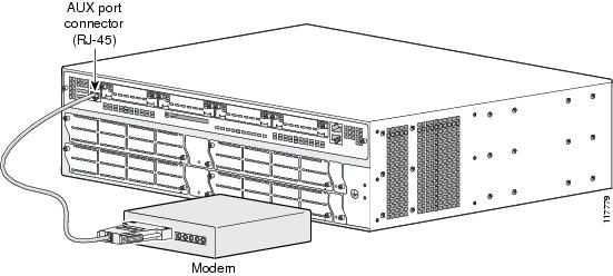
Connecting a Modem to the Auxiliary Port
To connect a modem to the auxiliary port on the router, follow these steps:
Step 1
Step 2
Figure 24 Connecting a Modem to the Auxiliary Port on a Cisco 3825 and 3825-NOVPN Router
Figure 25 Connecting a Modem to the Auxiliary Port on a Cisco 3845 and 3845-NOVPN Router