-
Cisco 3800 Series Hardware Installation
-
Cisco Access Router USB Flash Module and USB eToken Hardware Installation Guide
-
Introduction to Cisco 3800 Series Routers Hardware Documentation
-
Overview of Cisco 3800 Series Routers
-
Preinstallation Requirements and Planning for Cisco 3800 Series Routers
-
Installing Cisco 3800 Series Routers in an Equipment Rack
-
Connecting Cables to Cisco 3800 Series Routers
-
Powering Up Cisco 3800 Series Routers
-
Troubleshooting Cisco 3800 Series Routers
-
Installing Network Modules in Cisco 3800 Series Routers
-
Installing Interface Cards in Cisco 3800 Series Routers
-
Installing SFP Modules in Cisco 3800 Series Routers
-
Installing CompactFlash Memory Cards in Cisco 3800 Series Routers
-
Installing and Upgrading Internal Components in Cisco 3800 Series Routers
-
 Feedback
Table Of Contents
Installing Cisco 3800 Series Routers in an Equipment Rack
Attaching Brackets to the Router for Rack Mounting
Installing the Router in a Rack
Attaching the Optional Cable Management Bracket
Installing Cisco 3800 Series Routers in an Equipment Rack
This document describes how to install Cisco 3800 series integrated services routers in an equipment rack. After mounting the router in the rack, you must connect the chassis to a reliable earth ground. These procedures are described in the following sections:
Before working on your Cisco router, refer to the safety information in the "Safety Recommendations" section on page 1 of "Preinstallation Requirements and Planning for Cisco 3800 Series Routers," and in the Cisco 2800 Series and Cisco 3800 Series Integrated Services Routers Regulatory Compliance and Safety Information document that accompanied the router.
Note
Cisco 3800 series routers are not designed to be placed on a desktop or table.
Cisco 3800 series routers are shipped with network modules, WAN interface cards (WICs), voice interface cards (VICs), power supplies, and other optional equipment that you ordered already installed. If you need to remove or install these or other items, we recommend that you do so before installing the router in a rack, when you have the best access and do not need to disconnect it from the network. For procedures, see the following documents:
•
•
•
You will also be able to remove and install components while the router is in the rack, with the following exceptions for the Cisco 3825 and 3825-NOVPN router:
•
•
•
•
Warning
Statement 1029
Warning
Rack-Mounting the Router
Mount the router in the equipment rack before making network and power connections.
Warning
Caution
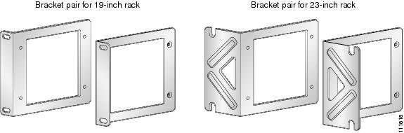
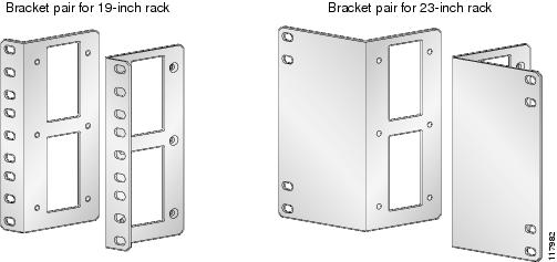
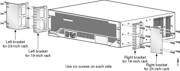
Cisco 3800 series routers can be installed in 19-inch and 23-inch racks using the brackets supplied with the router. These brackets are shown in Figure 1 and Figure 2. The left and right brackets are interchangeable.
Note
Figure 1 Rack-Mounting Brackets for Cisco 3825 and 3825-NOVPN Routers
Figure 2 Rack-Mounting Brackets for Cisco 3845 and 3845-NOVPN Routers
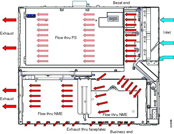
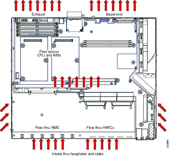
Airflow and access requirements may determine your mounting arrangement. See Figure 3 and Figure 4 for airflow diagrams, You can mount the router in the following ways:
•
•
•
Router Airflow Diagrams
The airflow differs in router models. Figure 3 and Figure 4 depict the airflow patterns.
Figure 3 Airflow Diagram for Cisco 3825 and 3825-NOVPN Routers
Figure 4 Airflow Diagram for Cisco 3845 and 3845-NOVPN Routers
Attaching Brackets to the Router for Rack Mounting
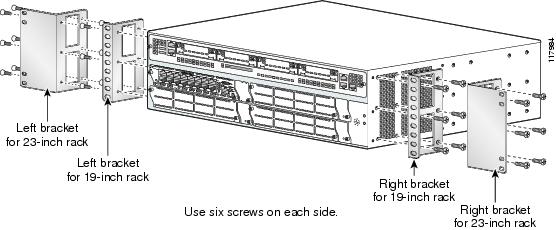
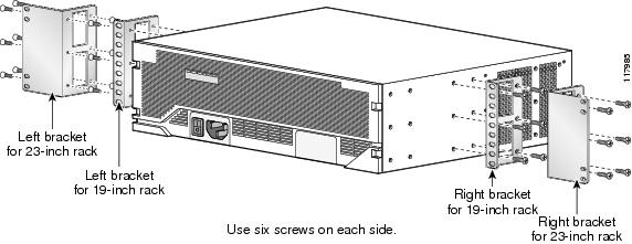
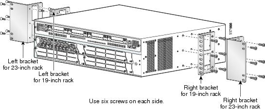
Attach the mounting brackets to the router, using a number 2 Phillips screwdriver to install the screws provided with the brackets. Figure 5 through Figure 8 show bracket attachment locations, using a Cisco 3845 and 3845-NOVPN router as an example.
Caution
Caution
Figure 5 Bracket Installation for Front Mounting
Figure 6 Bracket Installation for Rear Mounting
Figure 7 Bracket Installation for Center Mounting with Front Panel Forward
Figure 8 Bracket Installation for Center Mounting with Rear Panel Forward
Installing the Router in a Rack
Warning
This unit should be mounted at the bottom of the rack if it is the only unit in the rack.
When mounting this unit in a partially filled rack, load the rack from the bottom to the top with the heaviest component at the bottom of the rack.
If the rack is provided with stabilizing devices, install the stabilizers before mounting or servicing the unit in the rack. Statement 1006
Install the router in the rack, using two screws for each side. Rack-mounting screws should be supplied with the rack; they are not provided with the router.
Caution
Tip
Attaching the Optional Cable Management Bracket
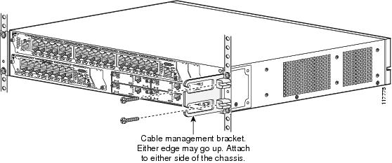
The optional cable management bracket (Cisco 3825 and 3825-NOVPN router only) provides attachment points for organizing and routing cables. Attach the cable management bracket to the left or right rack-mount bracket using the screw provided. You can attach the cable management bracket to either the upper or lower threaded hole. See Figure 9 for attachment locations.
Figure 9 Attaching the Optional Cable Management Bracket
Grounding the Router
Warning
Warning
You must connect the router chassis to a reliable earth ground. The ground wire must be installed in accordance with local electrical safety standards.
•
•
•
To connect the router to a reliable earth ground, follow these steps:
Step 1
•
•
Step 2
Step 3
Step 4
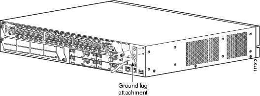
Figure 10 NEBS-Compliant Two-Hole Barrel Lug Ground Connection on Cisco 3825 and 3825-NOVPN Router
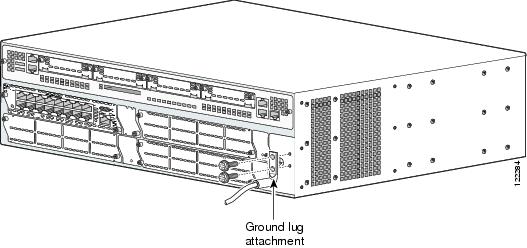
Figure 11 NEBS-Compliant Two-Hole Barrel Lug Ground Connection on Cisco 3845 and 3845-NOVPN Router
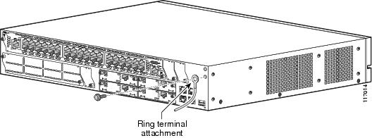
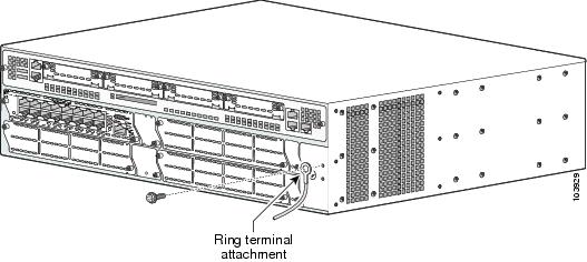
Figure 12 Ring Terminal Ground Connection on Cisco 3825 and 3825-NOVPN Router
Figure 13 Ring Terminal Ground Connection on Cisco 3845 and 3845-NOVPN Router
After the router has been installed and grounded, you can connect power cables; WAN, LAN, and voice cables; and cables for administrative access, as required for your installation. For cable connection procedures, see these sections of the "Connecting Cables to Cisco 3800 Series Routers" document:
•