Table Of Contents
Viewing and Managing SBCs
User Roles Required to View SBC Properties
Viewing SBC Properties in Logical Inventory
Viewing SBC DBE Properties
Viewing Media Address Properties
Viewing VDBE H.248 Properties
Viewing SBC SBE Properties
Viewing AAA Properties
Viewing H.248 Properties
Viewing Policy Properties
Viewing SIP Properties
Viewing SBC Statistics
Configuring SBC Components
Viewing and Managing SBCs
This chapter identifies and describes the properties for Session Border Controllers (SBCs) that appear in Cisco Prime Network Vision (Prime Network Vision) logical inventory. It also describes commands you can run to manage SBCs.
Session Border Controllers (SBCs) control and manage real-time multimedia traffic flows between IP network borders, handling signaling, and media. SBCs perform native IP interconnection functions required for real-time communications such as admission control, firewall traversal, accounting, signaling interworking, and quality-of-service (QoS) management. This includes:
• Protocol and media interworking
•Session routing
•Hosted Network Address Translation (NAT) and firewall traversal
•Security and AAA
•Intra- and inter-VPN interconnections and optimization
•Media transcoding with an external media server
The Cisco Prime Network platform provides fault management, configuration, and performance monitoring for SBC services. Prime Network SBC commands allow you to configure SBC components.
An SBC consists of combined DBE and SBE functionality:
•Data Border Element (DBE)—Responsible for media-related functions.
•Signaling Border Element (SBE)—Responsible for call signaling-related functions.
In addition, the SBC can operate in the following deployment models:
•Distributed Model (DM)—Contains only the SBE or DBE, resulting in a distributed SBC.
•Unified Model (UM)—Contains both the SBE and DBE, thereby implementing the SBE and DBE as a single device.
Note The existing Cisco SBC platforms support only DBE.
The following topics describe the SBC properties that are displayed in Prime Network Vision logical inventory:
•User Roles Required to View SBC Properties
•Viewing SBC Properties in Logical Inventory
•Viewing SBC DBE Properties
•Viewing SBC SBE Properties
•Viewing SBC Statistics
•Configuring SBC Components
User Roles Required to View SBC Properties
This topic identifies the GUI default permission or scope security level that is required to view SBC properties in Prime Network Vision. Prime Network determines whether you are authorized to perform a task as follows:
•For GUI-based tasks (tasks that do not affect elements), authorization is based on the default permission that is assigned to your user account.
•For element-based tasks (tasks that do affect elements), authorization is based on the default permission that is assigned to your account. That is, whether the element is in one of your assigned scopes and whether you meet the minimum security level for that scope.
For more information on user authorization, see the Cisco Prime Network 4.0 Administrator Guide.
The following tables identify the tasks that you can perform:
•Table 21-1 identifies the tasks that you can perform if a selected element is not in one of your assigned scopes.
•Table 21-2 identifies the tasks that you can perform if a selected element is in one of your assigned scopes.
By default, users with the Administrator role have access to all managed elements. To change the Administrator user scope, see the topic on device scopes in the Cisco Prime Network 4.0 Administrator Guide.
Table 21-1 Default Permission/Security Level Required for Viewing SBC Properties - Element Not in User's Scope
Task
|
Viewer
|
Operator
|
OperatorPlus
|
Configurator
|
Administrator
|
Viewing SBC properties
|
—
|
—
|
—
|
—
|
X
|
Using SBC Configuration and Monitoring Commands
|
—
|
—
|
—
|
X
|
X
|
Using SBC Show Commands
|
—
|
—
|
—
|
X
|
X
|
Table 21-2 Default Permission/Security Level Required for Viewing SBC Properties - Element in User's Scope
Task
|
Viewer
|
Operator
|
OperatorPlus
|
Configurator
|
Administrator
|
Viewing SBC properties
|
X
|
X
|
X
|
X
|
X
|
Using SBC Configuration and Monitoring Commands
|
—
|
—
|
—
|
X
|
X
|
Using SBC Show Commands
|
—
|
—
|
—
|
X
|
X
|
Viewing SBC Properties in Logical Inventory
To view SBC properties in Prime Network Vision logical inventory, right-click the element configured for SBC, then choose Inventory > Logical Inventory > Session Border Controller.
The SBC properties are displayed as shown in Figure 21-1.
Figure 21-1 SBC Properties in Logical Inventory
Table 21-3 describes the general SBC properties displayed in logical inventory.
Table 21-3 SBC Properties
Field
|
Description
|
Process
|
Process name, such as Session Border Controller.
|
Process Status
|
Status of the process, such as Running.
|
Application Version
|
SBC version number.
|
Mode
|
Mode in which the SBC is operating:
•Unified
•Distributed DBE
|
SBC Service Name
|
Name of the service.
|
Viewing SBC DBE Properties
The DBE controls media packet access to the network, provides differentiated services and QoS for different media streams, and prevents service theft.
To view SBC DBE properties, choose Logical Inventory > Session Border Controller > DBE.
Table 21-4 describes the DBE properties that appear in logical inventory.
Table 21-4 SBC DBE Properties
Field
|
Description
|
Process
|
Process name, such as DBE.
|
Process Status
|
Status of the process, such as Running.
|
Name
|
Name assigned to the DBE.
|
Type
|
Type of DBE, either DBE or virtual DBE (vDBE).
|
DBE Location Id
|
Unique identifier configured on each vDBE within a UM DBE.
|
Viewing Media Address Properties
A DBE uses a pool of sequential IPv4 media addresses as local media addresses.
To view SBC media address properties, choose Logical Inventory > Session Border Controller > DBE > Media Address.
Table 21-5 describes the SBC media address properties that are displayed in logical inventory.
Table 21-5 Media Address Properties
Field
|
Description
|
Address Range
|
IP addresses defined for the pool.
|
Port Range Lower
|
Lower end of the port range for the interface. If no range is specified, all possible Voice over IP (VoIP) port numbers are valid.
|
Port Range Upper
|
Upper end of the port range for the interface.
|
VRF Name
|
VRF that the interface is assigned to.
|
Service Class
|
Class of service (CoS) for each port range, such as fax, signaling, voice, or any.
|
Viewing VDBE H.248 Properties
To view VDBE H.248 properties, choose Logical Inventory > Session Border Controller > DBE > VDBE.
Table 21-6 describes the VDBE H.248 properties that are displayed in logical inventory.
Table 21-6 VDBE H.248 Properties
Branch
|
Description
|
H248 Controller
|
H.248 controller used by the DBE.
The Media Gateway Configuration (MGC) table displays the following information:
•Index—The number of the H.248 controller. The profile is used to interoperate with the SBE.
•Remote IP—The remote IP address for the H.248 controller.
•Remote Port—The remote port for the H.248 controller.
•Transport—The transport for communications with the remote device.
|
H248 Interface
|
The SBC H248 Control Interface table displays the following information:
•IP Address:
–In DM mode, the local IP address of the DBE used to connect to the SBE.
–In UM mode, the local IP address used to connect to the media gateway.
•Port—The port for the H.248 controller interface.
•Transport—The transport the H.248 controller interface uses.
•Association—The relationship between the SBE and the media gateway.
|
Viewing SBC SBE Properties
The SBE controls the access of VoIP signaling messages to the network core and manipulates the contents of these messages. It does this by acting as a SIP B2BUA or H.323 gateway.
To view SBC SBE properties, choose Logical Inventory > Session Border Controller > SBE.
Table 21-7 describes the information displayed in logical inventory for an SBE.
Table 21-7 SBC SBE Properties
Field
|
Description
|
Process
|
Name of the process, such as SBE.
|
Process Status
|
Status of the process, such as Running or Idle.
|
Name
|
Name assigned to this SBE.
|
Call Redirect Limit
|
Maximum number of times a call is redirected before the call is declared failed. The range is 0 to 100 with a default of 2.
|
On Hold Timeout
|
Amount of time, in milliseconds, that the SBE waits after receiving a media timeout notification from the DBE for an on-hold call before tearing down the call.
|
Viewing AAA Properties
For devices that support local and remote billing, the SBC can send billing records to a AAA server using the RADIUS protocol.
To view AAA properties, choose Logical Inventory > Session Border Controller > SBE > AAA.
Table 21-8 describes the AAA properties that appear in logical inventory for the SBC SBE.
Table 21-8 AAA Properties
Branch
|
Description
|
AAA Interface
|
The SBE AAA Interface table displays the following information:
•AAA Address—The local AAA interface address.
•Network ID—A unique identifier for the SBE.
|
Accounting
|
The Accounting Radius Client table displays the following information:
•Name—The name of the accounting client.
•Client Type—The type of client, either Accounting or Authentication.
|
Authentication
|
The Authentication Radius Client table displays the following information:
•Name—The name of the authentication client.
•Client Type—The type of client, either Accounting or Authentication.
|
Billing
|
The SBE Billing table displays the following information related to billing:
•LDR Check Time—The time of day (local time) to run the long duration record check.
•Local Billing Address—The local IP address for SBE billing. This IP address can be different from the local AAA IP address and is the IP address written in the bill records.
•Admin Status—The configuration status, available with the running-config command.
•Operational Status—The running status, available from the CLI. This entry indicates whether or not the billing interface is up. The status is derived from the interworking of the SBC and the AAA server.
|
Viewing H.248 Properties
The H.248 interface is used for signaling between an SBE and a DBE in distributed mode and between an SBE and a transcoding media gateway. The SBE or SBC acts as an H.248 MGC, and the transcoding device acts as an H.248 media gateway. The connection between the MGC and the media gateway is an H.248 link.
To view H.248 properties, choose Logical Inventory > Session Border Controller > H248.
Table 21-9 describes the H.248 properties that appear in logical inventory for the SBC SBE.
Table 21-9 H.248 Properties
Branch
|
Description
|
H248 Interface
|
The SBC H248 Control Interface table displays the following information:
•IP Address:
–In DM mode, the IP address used to connect the DBE and the MGC.
–In UM mode, the IP address used to connect the SBC and the media gateway.
•Port—The port for the H.248 controller interface.
•Transport—The transport the H.248 controller interface uses.
•Association—The relationship between the SBE and the media gateway.
|
Media Gateway
|
The Media Gateway table displays the following information:
•IP Address—The IP address of the media gateway.
•Codec List—A comma-separated list of the codecs supported.
|
Viewing Policy Properties
An SBC policy is a set of rules that define how the SBC treats different kinds of VoIP events. An SBC policy allows control of the VoIP signaling and media that pass through the SBC at an application level.
A policy set is a group of policies that can be active on the SBC at any one time. If a policy set is active, the SBC uses the rules defined within it to apply policy to events. Multiple policies can be set on a single SBC.
To view policy properties, choose Logical Inventory > Session Border Controller > Policy.
Table 21-10 describes the policy properties that appear in logical inventory for the SBC SBE.
Table 21-10 Policy Properties
Branch
|
Description
|
Blacklist
|
The Blacklists table contains the following information:
•Name—The blacklist name.
•Type—The type of source that this blacklist applies to, such as critical or normal.
|
CAC Policy
|
A Call Admission Control (CAC) policy is used to define admission control.
The SBE CAC Policy Set table contains the following information:
•Policy Set Number—An identifying number the SBE has assigned to the policy set.
•First Table—A CAC policy table.
•Status—Whether the policy is active or inactive. If the policy is active, the SBC applies the defined rules to events.
•First CAC Scope—The scale that the CAC applies for, such as source adjacency or destination adjacency. This is the first CAC table used for CAC policy match.
•Description—A brief description of the policy set.
|
Call Policy
|
A call policy set is used for number analysis and routing.
The SBE Call Policy Set table contains the following information:
•Policy Set Number—An identifying number the SBE has assigned to the policy set.
•Status—Whether the policy is active or inactive. If the policy is active, the SBC applies the defined rules to events.
•First Call Table—The first call table used for call policy match.
•Description—A brief description of the policy set.
|
Codec List
|
The SBE Codec List table contains the following information:
•Name—The name of the codec list.
•Codecs—The codecs contained in each list.
|
Current Blacklisting
|
The Current Blacklistings table contains the following information:
•Type—The type of source this blacklist applies to. Blacklists are used to block certain VoIP services that meet specified conditions.
•Event Type—The type of event this blacklist applies to, such as CORRUPT_MESSAGE.
•Is All Source Addresses—Whether the blacklist applies to all source IP addresses:
–True—Ignore any IP address in the Source Address field.
–False—Use the IP address in the Source Address field.
•Source Address—The IP address that this blacklist applies to.
•Source Port Number—The port number that this blacklist applies to.
•Source Port Type—The type of port this blacklist applies to. All is a valid entry.
•Time Remaining—The amount of time, in hours, minutes, or seconds, before the blacklist is removed.
|
Hunting Trigger
|
The hunting trigger enables the SBC to search for other routes or destination adjacencies if an existing route fails.
The Global Hunting Trigger List table contains the following information:
•Hunting Mode—Indicates the protocol to use to search for routes, such as Session Initiation Protocol (SIP).
•Hunting Triggers—The SIP responses, such as 468 or 503, that indicate the SBC is to search for an alternate route or destination adjacency. SIP responses are defined in RFC3261.
|
QoS Profile
|
QoS profiles can be used by CAC policies and are used exclusively for marking IP packets.
The QoS Profile table contains the following information:
•Name—The name of the QoS profile.
•Class of Service—The type of call this profile applies to, such as voice, video, signaling, or fax.
•Marking Type—The type of marking to be applied to the IP packet. Options include Passthrough, Differentiated Service Code Point (DSCP), and IP Precedence/ToS.
•IP Precedence—If the marking type is IP Precedence, the specified precedence, either 0 or 1.
•ToS—If the marking type is ToS, the ToS value.
•DSCP—If the marking type is DSCP, the DSCP value.
|
SDP
|
The Session Description Protocol (SDP) content pane contains the following tabs, each with their respective table:
•SBE SDP Policy Table:
–Instance Name—The name of the policy table.
–SBE SDP Match Table—The name of the SDP match table.
•SBE SDP Match Table:
–Instance Name—The name of the SDP match table.
–Match Strings—The match criteria.
–Table Type—The type of table, either Blacklist or Whitelist.
|
Viewing SIP Properties
To view SIP properties, choose Logical Inventory > Session Border Controller > SIP.
Table 21-11 describes the SIP entries that appear in logical inventory for the SBC SBE.
Table 21-11 SIP Properties
Branch
|
Description
|
SIP Account
|
The SBE Account table contains the following information:
•Name—The name of the account associated with the adjacencies.
•Adjacencies—The identified adjacencies.
|
SIP Adjacency
|
An adjacency represents a signaling relationship with a remote call agent. One adjacency is defined per external call agent. Each adjacency belongs within an account. Each incoming call is matched to an adjacency, and each outgoing call is routed out over a second adjacency.
The SBC SIP Adjacencies table contains the following information:
•Name—The adjacency name.
•Status—The status of the adjacency, either Attached or Detached.
•Signaling Address—The local IP address and port (optional) for communications.
•Signaling Peer—The remote IP address and port (optional) for communications.
•Description—A brief description of the adjacency.
|
SIP Adjacency Group
|
The Adjacencies Groups table contains the following information:
•Name—The name of the SIP adjacency group.
•Adjacencies—The adjacencies that belong to the group.
|
SIP Profile
|
The SBC can be configured with whitelist and blacklists profiles on SIP messages. The following types of SIP profiles are available:
•Header profile—A profile based on SIP header information.
•Method profile—A profile based on SIP method strings.
•Option profile—A profile based on SIP option strings.
•Parameter profile—A profile based on SIP parameters.
|
SIP Profile >
Header Profile
|
The SIP Header Profiles table contains the following information:
•Name—The name of the SIP header profile.
•Status—Whether or not the profile is in use.
•Profile Type—The type of profile:
–Whitelist—Accepts SIP requests that match the profile.
–Blacklist—Rejects SIP requests that match the profile.
•Description—A brief description of the profile.
|
SIP Profile >
Method Profile
|
The SIP Method Profiles table contains the following information:
•Name—The name of the SIP method profile.
•Status—Whether or not the profile is in use.
•Profile Type—The type of profile:
–Whitelist—Accepts SIP requests that match the profile.
–Blacklist—Rejects SIP requests that match the profile.
•Description—A brief description of the profile.
•Is Passthrough—Whether or not passthrough is enabled:
–True—Permits message bodies to be passed through for nonvital methods that match this profile.
–False—Strips the message body out of any nonvital SIP messages that match this profile.
|
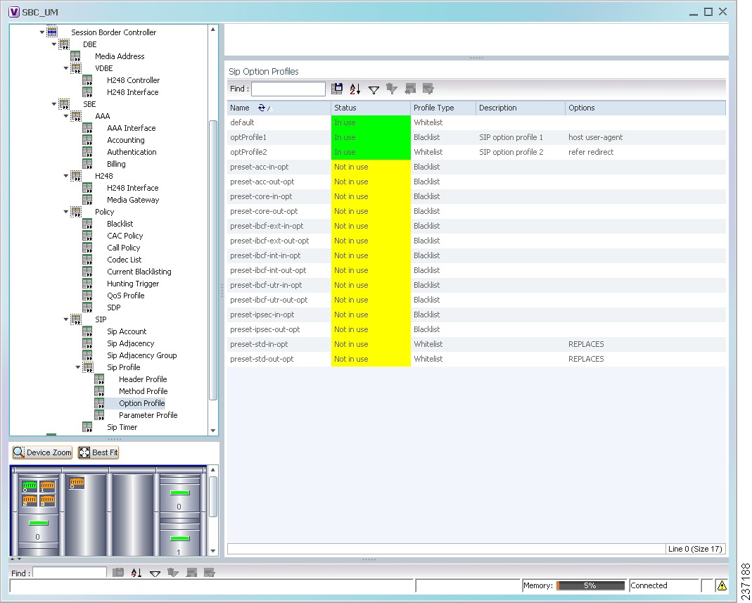
SIP Profile >
Option Profile
|
The SIP Option Profiles table contains the following information:
•Name—The name of the SIP option profile.
•Status—Whether or not the profile is in use.
•Profile Type—The type of profile:
–Whitelist—Accepts SIP requests that match the profile.
–Blacklist—Rejects SIP requests that match the profile.
•Description—A brief description of the profile.
•Options—The SIP option strings that define this profile, such as host user-agent, refer redirect, or replaces.
|
SIP Profile >
Parameter Profile
|
The SIP Parameter Profiles table contains the following information:
•Name—The name of the SIP parameter profile.
•Status—Whether or not the profile is in use.
•Description—A brief description of the profile.
|
SIP Timer
|
The SBE SIP Timer table contains the following information:
•TCP Connect Timeout—The time, in milliseconds, that the SBC waits for a SIP TCP connection to a remote peer to complete before failing that connection. The default is 1000 milliseconds.
•TCP Idle Timeout—The minimum time, in milliseconds, that a TCP socket does not process any traffic before it closes the connection. The default is 120000 milliseconds (2 minutes).
•TLS Idle Timeout—The minimum time, in milliseconds, that a Transport Layer Security (TLS) socket does not process traffic before it closes the connection.
•Invite Timeout—The time, in seconds, that the SBC waits for a final response to an outbound SIP invite request. The default is 180 seconds. If no response is received during that time, an internal request timeout response is generated and returned to the caller.
•UDP First Retransmit Interval—The time, in milliseconds, that the SBC waits for a UDP response or ACK before sending the first retransmission of a signal. The default value is 500 milliseconds.
•UDP Max Retransmit Interval—The maximum time interval, in milliseconds, for an SBC to retransmit a signal. The maximum retransmission interval is 4000 milliseconds (4 seconds).
•UDP Response Linger Period—The time, in milliseconds, for which the SBC retains negative UDP responses to invite requests. The default value is 32000 milliseconds (32 seconds).
|
Viewing SBC Statistics
The following commands can be launched from the inventory by right-clicking an SBC node and selecting Commands. The table below lists the SBC configuration commands. Additional commands may be available for your devices. New commands are often provided in Prime Network Device Packages, which can be downloaded from the Prime Network software download site. For more information on how to download and install DPs and enable new commands, see the information on "Adding Additional Device (VNE) support" in the Cisco Prime Network 4.0 Administrator Guide.
Command
|
Navigation
|
Description
|
Current 15 Min Statistics
|
Show > PM >
|
Based on the command selected, the device's statistics are displayed.
|
Current 5 Min Statistics
|
Current Day Statistics
|
Current Hour Statistics
|
H.248 Statistics
|
Previous 15 Minutes Statistics
|
Previous 5 Minutes Statistics
|
Previous Day Statistics
|
Previous Hour Statistics
|
CPS Data
|
Media Statistics
|
Show >
|
Components
|
Configuring SBC Components
The following commands can be launched from the logical inventory by right-clicking the Session Border Controller node. Before executing any commands, you can preview them and view the results. If desired, you can also schedule the commands.
The table below lists the SBC components configuration commands. Additional commands may be available for your devices. New commands are often provided in Prime Network Device Packages, which can be downloaded from the Prime Network software download site. For more information on how to download and install DPs and enable new commands, see the information on "Adding Additional Device (VNE) support" in the Cisco Prime Network 4.0 Administrator Guide.
For details on the software versions Prime Network supports for the listed supported network elements, see Cisco Prime Network 4.0 Supported Cisco VNEs.
Note You might be prompted to enter your device access credentials while executing a command. Once you have entered them, these credentials will be used for every subsequent execution of a command in the same GUI client session. If you want to change the credentials, click Edit Credentials. The Edit Credentials button will not be available for SNMP commands or if the command is scheduled for a later time.
You can configure the following SBC components using the commands described in this section.
Command
|
Navigation
|
Description
|
SIP Adjancencies
|
Add SIP Adjacency
|
Right-click the SBC node > Commands > Add > SIP Adjacency
|
Add an SIP adjacency or update an existing SIP adjacency.
|
Update SIP Adjacency
Delete SIP Adjacency
|
In the SIP Adjacencies window, right-click the adjacency instance > Commands > Update /Delete > SIP Adjacency.
|
Add SIP Adjacency Outbound AuthRealm
Update SIP Adjacency Outbound AuthRealm
Delete SIP Adjacency Outbound AuthRealm
|
In the SIP Adjacencies window, right-click the SIP adjacency instance > Commands > Add /Update/Delete > SIP Adjacency Outbound AuthRealm.
|
Use this command to add a SIP adjacency outbound authentication realm.
|
SIP Header Profiles
|
Add SIP Header Profile
|
Right-click the SBE node > Commands > Add > SIP Header Profile
|
Use the Add SIP Header Profile command to add a SIP header profile.
Note When you add a new SIP header profile, you can add three headers to it. You can add more headers to the new SIP header profile after it is discovered.
|
Update SIP Header Profile
Delete SIP Header Profile
|
In the SIP Header Profiles window, right-click the profile > Commands > Update/Delete > SIP Header Profile
|
Add SIP Header Profile Header
|
In the SIP Header Profiles window, right-click the SIP header profile instance > Commands > Add > SIP Header Profile Header
|
Use the Add Header command to add a header to an existing header profile
|
Delete SIP Header Profile Header
|
In the header profile properties window, right-click the header you want to remove and choose > Commands > Delete > SIP Header Profile Header
|
Delete a header from a header profile.
|
Add SIP Header Profile Entry
|
Right-click the SBE node > Commands > Add > SIP Header Profile Entry
|
Use this command to add an entry to an existing SIP header profile header.
|
Update SIP Header Profile Entry
Delete SIP Header Profile Entry
|
Right-click an entry in the SIP Header Profile Header Properties window > Commands > Update/Delete > SIP Header Profile Entry
|
Update or deletean existing SIP Header Profile entry in the SIP Header Profile Header Properties window.
|
Add SIP Header Profile Condition
|
Expand the SBE node, SIP node, and SIP Profile node, and click the Header Profile node > double-click a header profile to open the SIP Header Profile Properties window > Double-click a header > Right-click an entry > Commands > Add > SIP Header Profile Condition
|
Use this command to add a condition to a SIP header profile header.
|
SIP Option Profiles
|
Add SIP Option Profile
|
Right-click the SBE node > Commands > Add > SIP Option Profile
|
Configure SIP option profile paramters such as option profile type (whitelist or blacklist), profile options, and so on.
|
Update SIP Option Profile
Delete SIP Option Profile
|
Right-click a profile in the SIP Option Profile window > Commands > Update/Delete > SIP Option Profile
|
Add SIP Parameter Profile
|
Right-click the SBE node > Commands > Add > SIP Parameter Profile
|
Configure SIP parameter profile.
|
Delete SIP Parameter Profile
|
Click the Parameter Profile node, right-click the profile > Commands > Delete > SIP Parameter Profile
|
Add SIP Parameter Profile Parameter
|
Expand the SBE node, SIP node, SIP Profile node > click the Parameter Profile > right-click the profile instance > Commands > Add > SIP Parameter Profile Parameter
|
Add, update, or delete parameter in SIP parameter profiles.
Specify the parameter name to be updated and the name of the profile in which you want to add or update the parameter.
|
Update SIP Parameter Profile Parameter
Delete SIP Parameter Profile Parameter
|
Double-click the profile that contains the parameter > right-click the parameter > Commands > Update/Delete > SIP Parameter Profile Parameter
|
Blacklists
|
Add Blacklist
|
Right-click the SBE node > Commands > Add > Blacklist
|
Add or delete blacklist in the SBC node. Specify the IP address, port type, and the port number to be blacklisted.
|
Delete Blacklist
|
In the Configured Blacklist Properties window, right-click the blacklist > Commands > Delete > Blacklist
|
Add Blacklist Reason
|
Right-click the blacklist instance > Commands > Add > Blacklist Reason
|
Add, modify, or delete a blacklist reason for the blacklisted node in SBC.
|
Update Blacklist Reason
Delete Blacklist Reason
|
In the Configured Blacklist Properties window, right-click a blacklist reason > Commands > Update/Delete > Blacklist Reason
|
Call Admission Control (CAC) Policies
|
Add CAC Policy Set
|
Right-click the SBE node > Commands > Add > CAC Policy Set
|
Add, modify, or delete a CAC Policy Set
|
Update CAC Policy Set
Delete CAC Policy Set
|
In the CAC Policy Set window, right-click the policy set instance > Commands > Update/Delete > CAC Policy Set
|
Add CAC Policy Table
|
In the CAC Policy Set window, right-click the CAC policy instance > Commands > Add > CAC Policy Table
|
Add or modify a CAC policy table in an existing CAC policy set.
|
Update CAC Policy Table
Delete CAC Policy Table
|
Right-click a policy table in the CAC Policy Set Properties window > Commands > Update/Delete > CAC Policy Table
|
Add CAC Rule Entry
|
Right-click a policy table > Commands > Add > CAC Rule Entry
|
Add or modify a CAC rule entry in an existing CAC policy table.
|
Update CAC Rule Entry
Delete CAC Rule Entry
|
Right-click an entry in the CAC Rule Entry tab > Commands > Update/Delete > CAC Rule Entry
|
Add Call Policy Set
|
Right-click the SBE node > Commands > Add > Call Policy Set
|
Add, modify, or delete a Call Policy Set.
Note When you add a new call policy set, you can add three call policy tables. You can add more tables after the call policy set you created is discovered.
|
Update Call Policy Set
Delete Call Policy Set
|
Right-click a policy set in the Call Policy Set window > Commands > Update > Call Policy Set
|
Add Call Policy Table
|
In the Call Policy Set window, right-click the policy set > Commands > Add > Call Policy Table
|
Add, modify, or delete call policy tables
|
Update Call Policy Table
Delete Call Policy Table
|
Double-click a policy set, then right-click a policy table > Commands > Update > Call Policy Table
|
Add Call Rule Entry
|
Right-click a policy table > Commands > Add > Call Rule Entry
|
Add, modify, or delete an entry from an existing call policy table.
|
Update Call Rule Entry
Delete Call Rule Entry
|
Double-click a policy table, then right-click an entry > Commands > Update/Delete > Call Rule Entry
|
Codec Lists
|
Add Codec List
|
Right-click the SBE node > Commands > Add > Codec List
|
Add, or delete a Codec List
|
Delete Codec List
|
In the Codec List window, right-click a list instance > Commands > Delete > Codec List
|
Add Codec List Entry
|
In the Codec List window, right-click the codec list instance > Commands > Add > Codec List Entry
|
Add, modify, or delete an entry in a codec list.
|
Update Codec List Entry
Delete Codec List Entry
|
Double-click the codec list, then right-click the codec > Commands > Update /Delete> Codec List Entry
|
Media Addresses
|
Add Media Address
|
Right-click the SBE node > Commands > Add > Media Address
|
Add a media address or media Address DBE with parameters indicating that media address is managed by the Data Border Element (DBE) or Media Gateway Configuration (MGC).
|
Add Media Address Dbe
|
Right-click the DBE node > Commands > Add > Media Address Dbe
|
Delete Media Address
|
Expand the DBE node and click the Media Address node > right-click the media address > Commands > Delete > Media Address
|
Delete an existing media address from the DBE node.
|
QoS Profiles
|
Add QoS Profile
|
Right-click the SBE node > Commands > Add > QoS Profile
|
Configure QoS profile on a SBE node
|
Update QoS Profile
Delete QoS Profile
|
Right-click the profile in the QoS Profile window > Commands > Update > QoS Profile
|

 Feedback