Table Of Contents
Monitoring Cable Technologies
User Roles Required to Work with Cable Technologies
Viewing the Cable Broadband Configuration Details
Viewing the DTI Client Configuration Details
Viewing the QAM Domain Configuration Details
Viewing the MAC Domain Configuration Details
Viewing the Narrowband Channels Configuration Details
Viewing the Wideband Channels Configuration Details
Viewing the Fiber Node Configuration Details
Configure Cable Ports and Interfaces
View Upstream and Downstream Configuration for Cable
Configure QAM
View QAM Configurations
Configure DEPI and L2TP
Monitoring Cable Technologies
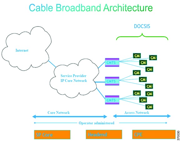
Cable broadband communication operates in compliance with the Data Over Cable Service Interface Specification (DOCSIS) standard which prescribes multivendor interoperability and promotes a retail model for the consumer's direct purchase of a cable modem (CM) of choice. Figure 27-1 depicts the architecture of the cable broadband in compliance with this standard:
Figure 27-1 Cable Broadband Architecture
DOCSIS defines two key devices necessary for broadband cable communication:
•
Cable Modem Termination System (CMTS) is a piece of equipment typically located in a cable company's headend or hubsite, and used to provide high speed data services, such as cable Internet or voice over Internet Protocol, to cable subscribers. A CMTS provides many of the same functions provided by the DSLAM in a DSL system. In order to provide these high speed data services, a cable company will connect its headend to the Internet via very high capacity data links to a network service provider. On the subscriber side of the headend, the CMTS enables the communication with subscribers' cable modems. A single CMTS can accommodate thousands of cable modems, and provides the connection point to the Internet backbone.
•
Cable Modem (CM) is a type of network bridge and modem that provides bi-directional data communication via radio frequency channels on a hybrid fiber-coaxial (HFC) and RFoG infrastructure. Cable modems are primarily used to deliver broadband Internet access in the form of cable Internet, taking advantage of the high bandwidth of a HFC and RFoG network. Usually located at the customer premises, terminates the cable line, and modulates/demodulates signals to and from the CMTS.
Data flowing from the CMTS to the Cable Modem is deemed downstream traffic. Data from the Cable Modem to the CMTS is upstream traffic. A DOCSIS binary configuration file provides the appropriate ISP parameters for cable modems to connect to the network.
There are two types of CMTS systems, which are explained below:
•
Integrated CMTS (I-CMTS)—In this type of CMTS, the contents of the downstream channel are directly modulated and transmitted by the Downstream RF Port.
•
Modular CMTS (M-CMTS)—In this type of CMTS, the contents of the downstream channel are encapsulated into a DEPI tunnel for transmission.
Cisco Systems offers a complete portfolio of standards-based cable products, solutions, and network management systems that enable integration of data, voice, and video services on a single multiservice cable IP network. Cisco offers the following CMTS systems:
•
The Cisco uBR7100 Series, Cisco uBR7200 Series, and Cisco uBR10012 Universal Broadband Routers combine a CMTS with a fully integrated Cisco IOSĀ® Software router.
•
Cisco RF Switch works with the Cisco uBR10012 to offer a new level of high availability suited for DOCSIS, EuroDOCSIS, or PacketCable applications. Together with the Cisco uBR10012, the Cisco RF Switch enables a fully redundant CMTS with no single point of failure, including the upconverter.
Topics covered in this section are:
•
User Roles Required to Work with Cable Technologies
•
Configure Cable Ports and Interfaces
•
View Upstream and Downstream Configuration for Cable
•
Configure QAM
•
View QAM Configurations
•
Configure DEPI and L2TP
User Roles Required to Work with Cable Technologies
Table 27-1 identifies the GUI default permission or device scope security level that is required to work with Prime Network Vision. Prime Network Vision determines whether you are authorized to perform a task as follows:
•
For GUI-based tasks (tasks that do not affect devices), authorization is based on the default permission that is assigned to your user account.
•
For element-based tasks (tasks that do affect elements), authorization is based on the default permission that is assigned to your account. That is, whether the element is in one of your assigned scopes and whether you meet the minimum security level for that scope.
For more information on user authorization, see the Cisco Prime Network 4.0 Administrator Guide.
By default, users with the Administrator role have access to all managed elements. To change the Administrator user scope, see the topic on device scopes in the Cisco Prime Network 4.10 Administrator Guide.
Table 27-1 Default Permission/Security Level Required for the Data Center Configurations
Task
|
Viewer
|
Operator
|
OperatorPlus
|
Configurator
|
Administrator
|
Viewing the Cable Broadband Configuration Details
|
X
|
X
|
X
|
X
|
X
|
Viewing the DTI Configuration Details
|
X
|
X
|
X
|
X
|
X
|
Viewing the QAM Domain Configuration Details
|
X
|
X
|
X
|
X
|
X
|
Viewing the MAC Domain Configuration Details
|
X
|
X
|
X
|
X
|
X
|
Viewing the Narrowband Channels Configuration Details
|
X
|
X
|
X
|
X
|
X
|
Viewing the Wideband Channels Configuration Details
|
X
|
X
|
X
|
X
|
X
|
Viewing the Fiber Node Configuration Details
|
X
|
X
|
X
|
X
|
X
|
Viewing the Cable Broadband Configuration Details
You can view the following Cable technology configurations:
•
DTI Client—The DOCSIS Timing Interface (DTI) client collects DTI server master clock, DOCSIS timestamp, and Time of Day information from the DTI Server. It interfaces with the DTI Server to provide Time, Frequency and Management interfaces to the Modular Cable Modem Termination System (M-CMTS) device.
•
QAM Domain—Quadrature Amplitude Modulation (QAM) domain
•
MAC Domain—A MAC domain is a logical subcomponent of a Cisco CMTS router and is responsible for implementing all DOCSIS functions on a set of downstream and upstream channels. The CMTS MAC domain typically includes one or more downstream paths and one or more upstream paths. Depending on the CMTS configuration, the CMTS MAC domain can be defined to have its downstream on one cable interface line card with its upstreams on another card, or one or more CMTS MAC domains per cable interface line card.
•
Narrowband Channels—A Narrowband Channel is a logical representation of a non-bonded channel that is a standard DOCSIS 1.x/2.0 protocol downstream channel that contains one RF channel. The wideband protocol utilizes the existing narrowband downstream channel for carrying the MAC management and signaling messages and the associated narrowband upstream for return data traffic and signaling.
•
Wideband Channels—A Wideband Channel or Bonded Group (BG) is a logical grouping of one or more physical RF channels over which MPEG-TS packets are carried. Wideband channel carries DOCSIS bonded packets encapsulated in MPEG-TS packets from a WCMTS to one or more WCMs. The wideband channel, comprising of one or more RF channels on the EQAM device, is used for DS data traffic. The US channels on the Cisco uBR-MC3GX60V or Cisco uBR10-MC5X20 cable interface line cards are used for US traffic.
•
Fiber Node—A Fiber Node allows the Multiple Server Operator (MSO) or service provider to configure the CMTS to be more intelligent by making Cisco IOS aware of how the cable plant is wired. The downstream channels of the cable plant must be accurately configured in the CMTS fiber nodes. This allows the CMTS to accurately signal the wideband modems on which the wideband channels are available to the modem.
Viewing the DTI Client Configuration Details
To view the DTI Client configuration details:
Step 1
Right-click the required device in Prime Network Vision and choose Inventory.
Step 2
In the logical inventory window, choose Logical Inventory > DTI Client. The DTI Client details are displayed in the content pane.
Table 27-2 describes the DTI Client configuration details.
Table 27-2 DTI Client Configuration Details
Field
|
Description
|
DTI Server Details
|
Server Status
|
The status of the server, which can be any one of the following:
• Free Run
• Warm Up
• Fast Tracking
• Normal
• Hold Over
• Client Stable
• Test
|
Root Server Clock Type
|
The clock type of the DTI Server, which can be any one of the following:
• ITU Type 1
• ITU Type 2
• ITU Type 3
• ITU STRATUM 3
|
Root Server Source
|
The clock source of the DTI server, which can be any one of the following:
• Internal
• External
• GPS
• None
|
Server Type
|
The type of DTI Server, which can be any one of the following:
• Root
• User Time
• NTPV 4
• GPS
|
Client Performance Stable
|
Indicates the stability of the performance of the DTI client.
|
Client Cable Advance Valid
|
Indicates the cable advance status of the DTI Server Frame.
|
TOD Setting Mode
|
The output of the Time of Day Setting mode (User time, NTP, GPS), which can be any one of the following:
• Short
• Verbose
Note The output is based on the TOD message sent by the DTI Server.
|
Time of Day
|
The date and time of the clock.
|
DTI Client Port Status
|
DTI Client
|
The name of the DTI client, which when clicked will take you to the relevant slot under the Physical Inventory node.
|
DTI Client Status
|
The status of the DTI client, which can be any of the following:
• Active
• Standby
|
Connected
|
Indicates whether the DTI Server is active in the DTI client port.
|
Viewing the QAM Domain Configuration Details
To view the QAM domain configuration details:
Step 1
Right-click the required device in Prime Network Vision and choose Inventory.
Step 2
In the logical inventory window, choose Logical Inventory > QAM Domain > QAM Domain name. The QAM Domain details are displayed north content pane.
Table 27-3 describes the QAM Domain configuration details.
Table 27-3 QAM Domain Configuration Details
Field
|
Description
|
QAM Domain ID
|
The unique identification code of the QAM domain.
|
QAM Domain
|
QAM Domain ID
|
The unique identification code of the QAM domain.
|
UDP Start Range
|
The starting port in the range of UDP ports for the video route.
|
UDP End Range
|
The ending port in the range of UDP ports for the video route.
|
QAM Block
|
The QAM block ID for the video route.
|
Viewing the MAC Domain Configuration Details
To view the MAC domain configuration details:
Step 1
Right-click the required device in Prime Network Vision and choose Inventory.
Step 2
In the logical inventory window, choose Logical Inventory > MAC Domains > MAC Domain name. The MAC Domain configuration details are displayed in the content pane.
Table 27-4 describes the MAC Domain configuration details.
Table 27-4 MAC Domain Configuration Details
Field
|
Description
|
MAC Domain Name
|
The name of the MAC domain.
|
Domain Status
|
The status of the MAC domain, which can be any one of the following:
• Up
• Down
• Administrative Up
• Administrative Down
• Unknown
|
Bundle
|
The bundle address associated with the MAC domain.
|
Active Remote DS
|
The downstream channel associated with the MAC domain.
|
Upstream Channels
|
US Channel ID
|
The unique identification code of the Upstream channel.
|
Status
|
The status of the upstream channel, which can be any one of the following:
• Up
• Down
• Administrative Up
• Administrative Down
• Unknown
|
Port
|
The port to which the upstream channel is associated with.
|
Frequency
|
The frequency of the upstream channel.
|
Channel width
|
The width of the upstream channel.
|
Modulation
|
The modulation value of the upstream channel.
|
Backoff End
|
The backoff end time of the upstream channel.
|
Backoff Start
|
The backoff start time of the upstream channel.
|
Downstream Channels
|
DS Channel ID
|
The unique identification code of the Downstream Channel.
|
Associated Narrowband
|
The name of the narrowband channel that is associated to the downstream channel.
|
Port
|
The port to which the downstream channel is associated with.
|
Status
|
The status of the downstream channel, which can be any one of the following:
• Up
• Down
• Administrative Up
• Administrative Down
• Unknown
|
Frequency
|
The frequency of the downstream channel.
|
Bandwidth
|
The bandwidth of the downstream channel.
|
Total Modem
|
The total number of modem for the downstream channel.
|
Modem Active
|
The number of modems active for the downstream channel.
|
Network Delay
|
The network delay (in terms of bits per second) in the downstream channel.
|
Viewing the Narrowband Channels Configuration Details
To view the Narrowband channels configuration details:
Step 1
Right-click the required device in Prime Network Vision and choose Inventory.
Step 2
In the logical inventory window, choose Logical Inventory > Narrowband Channels > Narrowband channel cable. The Narrowband channels configuration details are displayed in the content pane.
Table 27-5 describes the Narrowband channels configuration details.
Table 27-5 Narrowband Channels Configuration Details
Field
|
Description
|
Name
|
The name of the narrowband channel.
|
Channel Status
|
The status of the narrowband channel, which can be any one of the following:
• Up
• Down
• Unknown
|
DS ID
|
The identification code of the downstream channel associated with the narrowband channel.
|
RF Channel ID
|
The identification code of the Radio Frequency (RF) channel associated with the narrowband channel.
|
Bandwidth
|
The percentage of bandwidth available for the narrowband channel.
|
Downstream ID
|
The link to the downstream channel that is associated to the narrowband channel.
|
Wideband Associations
|
Associated Entity
|
The wideband channel that is associated to the narrowband channel, which when clicked will take you to the relevant wideband channel configuration under the Wideband Channels node.
|
Bandwidth
|
The percentage of bandwidth available for the wideband channel.
|
Viewing the Wideband Channels Configuration Details
To view the Wideband channels configuration details:
Step 1
Right-click the required device in Prime Network Vision and choose Inventory.
Step 2
In the logical inventory window, choose Logical Inventory > Wideband Channels > Wideband cable. The Wideband channels configuration details are displayed in the content pane.
Table 27-6 describes the Wideband channels configuration details.
Table 27-6 Wideband Channels Configuration Details
Field
|
Description
|
Wideband Name
|
The name of the wideband channel.
|
Status
|
The status of the wideband channel, which can be any one of the following:
• Up
• Down
• Administrative Up
• Administrative Down
• Unknown
|
Bonding Group ID
|
The unique identification code of the bonding group.
Note A bonding group is a logical grouping of one or more physical radio frequency (RF) channels over which wideband MPEG-TS packets are carried. By aggregating or "channel bonding" multiple RF channels, the wideband channel is capable of greater bandwidth capacity for downstream data traffic than a single narrowband channel.
|
Bundle
|
The bundle address associated with the wideband.
|
NB Channel Interface
|
The Narrowband (NB) channel interface associated with the wideband channel.
|
Reserved CIR
|
The Committed Information Rate (CIR) reserved for the wideband channel.
|
Total CIR
|
The total Committed Information Rate (CIR) associated to the Wideband channel available.
|
Multicasting Reserved CIR
|
Indicates the Reserved Committed Information Rate associated to the multicasting group of the Wideband channel.
|
Multicasting Total CIR
|
Indicates the Total Committed Information Rate associated to the multicasting group of the Wideband channel.
|
RF Channels
|
RF Channel ID
|
The unique identification code of the RF channel.
|
Port
|
The port to which the RF channel is associated with.
|
Bandwidth
|
The percentage of bandwidth available for the RF channel.
|
Channel Type
|
The type of the RF channel, which can be any one of the following:
• Primary
• Non-Primary
|
Frequency
|
The frequency (in terms of Mhz) allocated to the RF channel.
|
Modulation
|
The modulation (in terms of QAM) allocated to the RF channel.
|
Annex
|
The annexure that is allocated to the RF channel.
|
IP Address
|
The IP address that is assigned to the RF channel for downstream data transmission.
|
MAC Address
|
The MAC address that is assigned to the RF channel for downstream data transmission.
|
DEPI Remote ID
|
The Downstream External PHY Interface (DEPI) remote session ID that is assigned to the RF channel.
|
Viewing the Fiber Node Configuration Details
To view the Fiber Node configuration details:
Step 1
Right-click the required device in Prime Network Vision and choose Inventory.
Step 2
In the logical inventory window, choose Logical Inventory > Fiber NOde. The Fiber Node configuration details are displayed in the content pane.
Table 27-7 describes the Fiber Node configuration details.
Table 27-7 Fiber Node Configuration Details
Field
|
Description
|
Fiber Node Number
|
The unique number assigned to the Fiber node.
|
Total DS Channels
|
The total number of downstream channels associated to the fiber node.
|
Total US Channels
|
The total number of upstream channels associated to the fiber node.
|
Status
|
The status of the fiber node, which can be any one of the following:
• Valid
• Invalid
|
Configure Cable Ports and Interfaces
These commands help in configuring the cable ports and IP interface. The table below lists the navigation of each of these commands. To run the these commands, the software on the network element must support the technology. Before executing any commands, you can preview them and view the results.
For details on the supported device list for these configuration commands and the software versions Prime Network supports for the supported network elements, see Cisco Prime Network 4.0 Supported Cisco VNEs.
Note
You might be prompted to enter your device access credentials while executing a command. Once you have entered them, these credentials will be used for every subsequent execution of a command in the same GUI client session. If you want to change the credentials, click Edit Credentials. The Edit Credentials button will not be available for SNMP commands or if the command is scheduled for a later time.
Configure Cable Ports
Command
|
Navigation
|
Description
|
Modify Port
|
Physical Inventory > Ethernet Slot > navigate to Ethernet port > Commands > Configuration > Port
|
Controls a variety of RFGW port characteristics (status of port, IP address type and so forth).
|
Modify Cable Port
|
Physical Inventory > Chassis > Slot > Subslot > Cable > Commands > Configuration > Port
|
Controls a variety of uBR10000 port characteristics (status of port, bundle ID and so forth).
|
Configure Downstream Port
|
Physical Inventory > Chassis > Slot > Subslot > Cable > Commands > Configuration > Downstream
|
Configure and enable the downstream ports on the Cisco uBR10K card. Configure parameters like modulation rate, downstream interleave depth in number of rows of code words, and so on.
|
Create Upstream Port
Modify Upstream Port
|
Physical Inventory > Chassis > Slot > Subslot > Cable or Ethernet port > Commands > Configuration > Upstream
|
Create or modify an upstream port.
|
Configure Cable Interfaces
Command
|
Navigation
|
Description
|
Create IP Interface
|
Logical Inventory > Routing Entities > Routing Entity > Commands > Configuration
|
Configure IP interface as part of the routing entity for the selected device.
|
Modify IP Interface
Delete IP Interface
|
Logical Inventory > Routing Entities > Routing Entity > select an interface > Commands > Configuration
|
Changes or removes descriptive information that is displayed in GUI clients when the interface is selected.
|
View Upstream and Downstream Configuration for Cable
Command
|
Navigation
|
Description
|
Show > Upstream
Show > Downstream
|
Physical Inventory > Ethernet Slot > navigate to Ethernet port > Commands > Configuration > Port
|
View the configured upstream and downstream rate for the selected cable.
|
Configure QAM
These commands help in configuring the Quadrature Amplitude Modulation (QAM) domain for the RF channel. The table below lists the navigation of each of these commands. To run the these commands, the software on the network element must support the technology. Before executing any commands, you can preview them and view the results.
For details on the supported device list for these configuration commands and the software versions Prime Network supports for the supported network elements, see Cisco Prime Network 4.0 Supported Cisco VNEs.
Note
You might be prompted to enter your device access credentials while executing a command. Once you have entered them, these credentials will be used for every subsequent execution of a command in the same GUI client session. If you want to change the credentials, click Edit Credentials. The Edit Credentials button will not be available for SNMP commands or if the command is scheduled for a later time.
Configure RF and Frequency Profiles
Command
|
Navigation
|
Description
|
Create RF Profile
Modify RF Profile
Delete RF Profile
|
NE > Commands > Configuration > RF Profile
|
Configures a combination of RF attributes to be used across all line cards in the chassis.
|
Delete Frequency Profile
Create Lane
Create Block
|
NE > Commands > Configuration > Frequency Profile
|
Configure the frequency profile at the port level.
These user-defined frequency scheme provides flexibility to define each lane and block start frequencies. These frequency profiles can then be applied to the port in this scheme.
|
Configure QAM Port and Channel
Command
|
Navigation
|
Description
|
Modify QAM Port
Modify QAM Channel
|
Physical Inventory > Chassis > Slot > QAM > Commands > Configuration
|
Modify the QAM port and channel.
|
View QAM Configurations
Command
|
Navigation
|
Description
|
Show > RF Profile
Show > Frequency Profile
|
NE > Commands
|
Display RF and Frequency profiles created on the device.
|
Show > QAM Port
Show > QAM Channel
|
Physical Inventory > Chassis > Slot > QAM > Commands
|
Displays cable information configured on the QAM channel and port.
|
Configure DEPI and L2TP
These commands help in configuring the Downstream External PHY Interface (DEPI) and Layer 2 Tunnel Protocol (L2TP). The table below lists the navigation of each of these commands. To run these commands, the software on the network element must support the technology. Before executing any commands, you can preview them and view the results.
For details on the supported device list for these configuration commands and the software versions Prime Network supports for the supported network elements, see Cisco Prime Network 4.0 Supported Cisco VNEs.
Note
You might be prompted to enter your device access credentials while executing a command. Once you have entered them, these credentials will be used for every subsequent execution of a command in the same GUI client session. If you want to change the credentials, click Edit Credentials. The Edit Credentials button will not be available for SNMP commands or if the command is scheduled for a later time.
Configure DEPI Class and Tunnel
Command
|
Navigation
|
Description
|
Create DEPI Class
Delete DEPI Class
Create DEPI Tunnel
Modify DEPI Tunnel
Delete DEPI Tunnel
|
NE > Commands > Configuration > DEPI
|
Configures template of DEPI control plane and tunnel configuration settings.
|
Configure L2TP Class
Command
|
Navigation
|
Description
|
Create L2TP Class
Modify L2TP Class
Delete L2TP Class
|
NE > Commands > Configuration > L2TP
|
Configures a template of Layer 2 Tunnel Protocol (L2TP) control plane configuration settings.
|
View DEPI Tunnel, DEPI Session, and L2TP Class
Command
|
Navigation
|
Description
|
Show > L2TP Class
Show > DEPI Tunnel
Show > DEPI Session
Show > Cable DEPI Session
|
NE > Commands > Configuration
|
Displays Layer 2 Tunnel Protocol control plane configuration settings.
|
Displays DEPI tunnel configuration settings.
|
Displays DEPI session information and DEPI sessions configured on the line card.
|