-
Cisco Prime Network User Guide, 4.0
-
Preface
-
Setting Up Devices and Using the GUI Clients
-
Working with the Cisco Prime Network Vision Client
-
Viewing and Managing NE Properties
-
Device Configurations and Software Images
-
Working with Prime Network Vision Maps
-
Working with Links
-
Labeling NEs Using Business Tags
-
Tracking Faults Using Prime Network Events
-
Working with Tickets in Cisco Prime Network Vision
-
Working with Reports
-
Using Cisco PathTracer to Diagnose Problems
-
Monitoring Carrier Ethernet Services
-
Monitoring Carrier Grade NAT Properties
-
Monitoring DWDM Properties
-
Monitoring Ethernet Operations, Administration, and Maintenance Tool Properties
-
Monitoring Y.1731 IPSLA Configuration
-
IPv6 and IPv6 VPN over MPLS
-
Monitoring MPLS Services
-
Viewing IP and MPLS Multicast Configurations
-
Monitoring MToP Services
-
Viewing and Managing SBCs
-
Monitoring AAA Configurations
-
Monitoring IP Pools
-
Monitoring BNG Configurations
-
Monitoring Mobile Technologies
-
Monitoring Data Center Configurations
-
Monitoring the Cable Technologies
-
Monitoring ADSL2+ and VDSL2 Technology Enhancements
-
Icon and Button Reference
-
Glossary
-
Index
-
 Feedback
Table Of Contents
Broadband Network Gateway (BNG): Overview
User Roles Required to Work With BNG
Working with BNG Configurations
View Broadband Access (BBA) Groups
Diagnose Subscriber Access Points
View Dynamic Host Configuration Protocol (DHCP) Service Profile
Viewing the Settings for a PPP Template
Monitoring BNG Configurations
These topics provide an overview of the Broadband Network Gateway (BNG) technology and describe how to monitor and view BNG configurations in Prime Network Vision:
•
Broadband Network Gateway (BNG): Overview
•
•
Broadband Network Gateway (BNG): Overview
Broadband Network Gateway (BNG) provides capabilities that help to improve the service provider's ability to manage the subscriber's services, and simplify overall network operations. BNG is a functionality that comprises subscriber management at a logical aggregation point in the network, which manages the subscriber's user experience through identification, address assignment, authentication, authorization, accounting, and various other features such as security, Quality of Service (QoS), and subscriber forwarding.
BNG represents the subscriber as a session, which is a logical point to enable services for a given subscriber. A subscriber is usually identified with the protocol that provides the IP address of the subscriber for address assignment. For example, a subscriber that uses the Point-to-Point Protocol (PPP) to connect to the network, receives its IP address through the PPP IP Control Protocol (IPCP) negotiation, and is represented as a PPP session. A subscriber that uses Ethernet to connect to the network receives its IP address through Dynamic Host Control Protocol (DHCP) and is represented as an IP session.
The purpose of deploying BNG at the provider edge is to better manage and enrich the subscriber experience.
BNG separates subscriber access functions from provider services and yields these benefits:
•
•
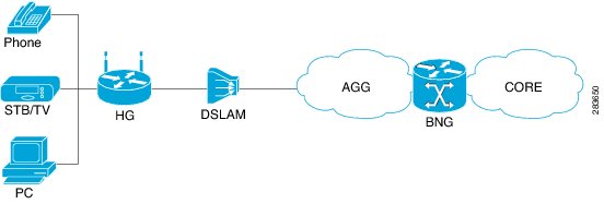
The network topology for BNG can be explained using the following models:
•
Figure 24-1 BNG Retail Model
•
The BNG Retail model is used for deployment in Prime Network.
Prime Network provides BNG support for Cisco Aggregation Service Router (ASR) 9000 series network elements.
The following topics describe more about the BNG configuration details:
•
•
User Roles Required to Work With BNG
This topic identifies the roles that are required to work with BNG. Prime Network determines whether you are authorized to perform a task as follows:
•
•
For more information on user authorization, see the topic on device scopes in the Cisco Prime Network 4.0 Administrator Guide.
Working with BNG Configurations
This topic contains the following sections:
•
•
•
•
•
•
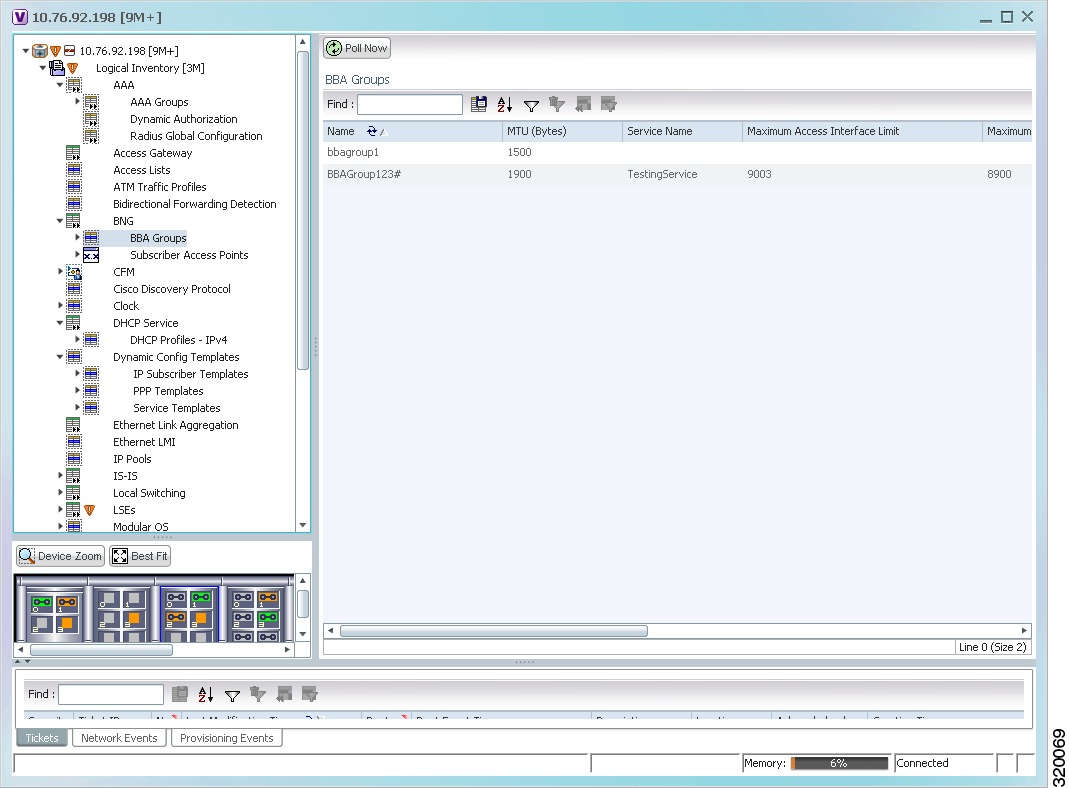
View Broadband Access (BBA) Groups
BBA groups refer to the configuration settings applicable to a subscriber session that are accessing the network through an access interface. The same group can be applied to multiple access interfaces. For example, the maximum session limit for an access interface.
To view the BBA group profile:
Step 1
Step 2
Figure 24-2 BBA Groups Content Pane
Step 3
Table 24-2 describes the fields that are displayed in the BBA Group Properties dialog box.
View Subscriber Access Points
Subscriber access points refer to the access interfaces that are named based on the parent interface. For example, bundle-ether 2.100.pppoe312. The subscribers on bundles (or bundle-VLANs) interfaces allow redundancy and are managed on the route processor (RP). However, the subscribers over physical interfaces are created and managed on the line card (LC) and are not redundant.
To view the subscriber access points profile:
Step 1
Step 2
Step 3
Table 24-3 describes the fields that are displayed in the Subscriber Access Point Properties dialog box.
Diagnose Subscriber Access Points
The following commands can be launched from the inventory by right-clicking the BNG > Subscriber Access Points node and selecting the Commands > Diagnose option. Before executing any commands, you can preview them and view the results. If desired, you can also schedule the commands. To find out if a device supports these commands, see the Cisco Prime Network 4.0 Supported Cisco VNEs.
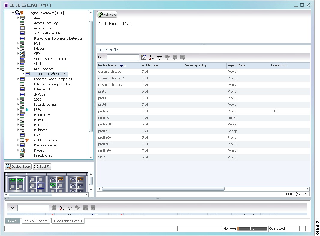
View Dynamic Host Configuration Protocol (DHCP) Service Profile
DHCP is used to automate host configuration by assigning IP addresses, delegating prefixes (in IPv6), and providing extensive configuration information to network computers.
DHCP has the capability to allocate IP addresses only for a specified period of time, which is known as the lease period. If a client device wants to retain the IP addresses for a period longer than the lease period, then the client must renew the lease before it expires. A client can renew the lease depending on the configuration time sent from the server. A REQUEST message is unicast by the client using the server's IP address. On receiving the REQUEST message, the server responds with an acknowledgment, and the client's lease is extended by the lease time configured in the acknowledgment message.
To view the DHCP service profile:
Step 1
Step 2
Figure 24-3 DHCP Profiles
Step 3
Table 24-5 describes the fields that are displayed in the DHCP Profile Properties dialog box.
View Dynamic Config Templates
A dynamic template is used to group configuration items, which are later applied to a group of subscribers. This template is globally configured through the command line interface (CLI). However, the template does not get applied to a subscriber interface as soon as it is configured. It must be activated using a control policy. Similarly, you must deactivate the template using a control policy to remove its association with the subscriber interface.
Ideally, you can activate more than one dynamic template on the same subscriber interface, for the same event or different events. The same dynamic-template can be activated on multiple subscriber interfaces through the same control policy.
Prime Network supports the following types of dynamic templates:
•
•
•
To view the configuration templates:
Step 1
Step 2
Step 3
Table 24-6 describes the fields that are displayed in the corresponding dialog box.
Viewing the Settings for a PPP Template
In addition to the above details, you can also view the following settings for a PPP template:
•
•
•
•
To view the settings:
Step 1
Step 2
Step 3
Table 24-7 describes the fields that are displayed in the corresponding dialog box.
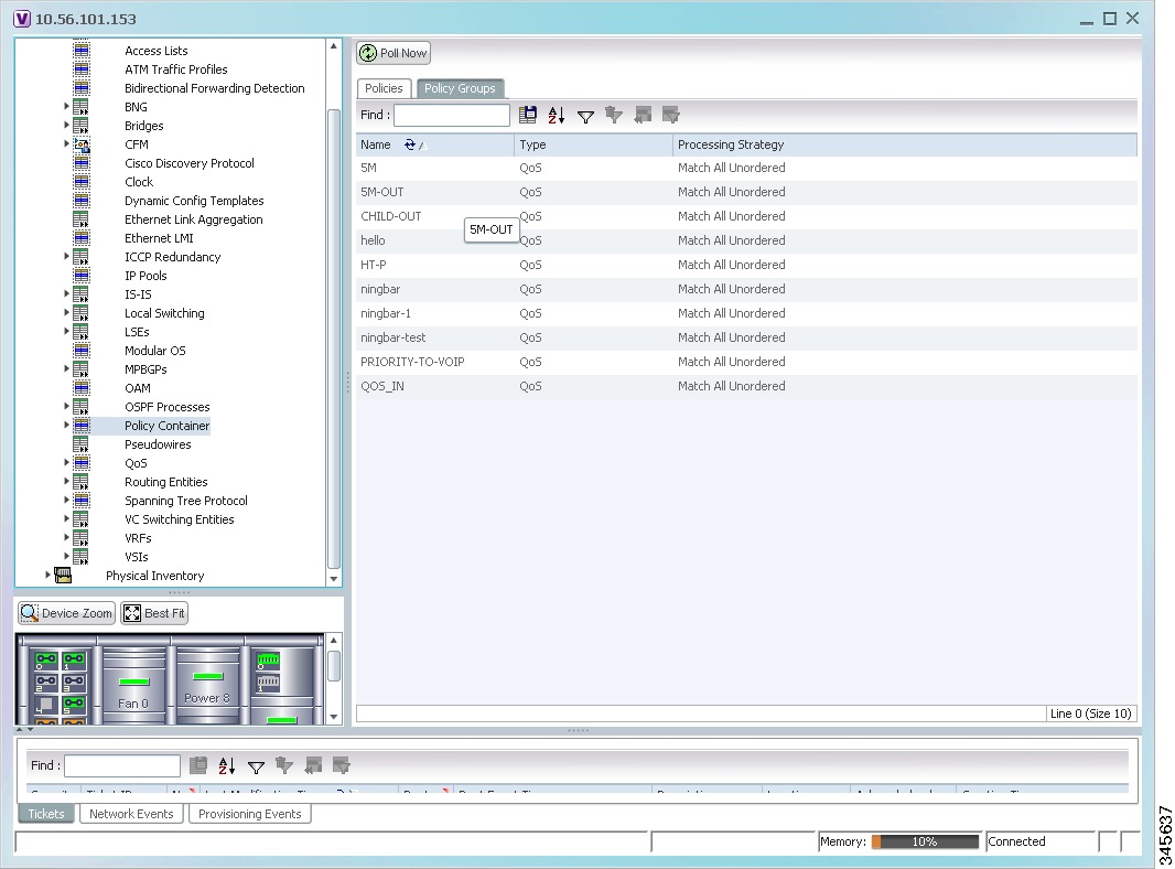
Viewing Policy Container
The Policy Container node in the logical inventory lists all the available service groups and service policies that are associated with service templates, BBA groups, and subscriber access points.
To view the service group and service policy profiles:
Step 1
Step 2
Figure 24-4 Policy Container
Step 3
Step 4
Table 24-8 describes the fields that are displayed in the Policy Group Properties dialog box.
Step 5
Viewing QoS Profile
QoS or Quality of services is the technique of prioritizing traffic flows and specifying preferences for forwarding packets with higher priority. The QoS node in the logical inventory lists all the services configured for the selected network element.
To view the QoS profile:
Step 1
Step 2
Step 3
Table 24-10 describes the fields that are displayed in the Class of Services Properties dialog box.