Feedback
Table Of Contents
Provisioning Process for IP QoS
Creating QoS Link Candidate Objects
Selecting CE Device Interfaces for QoS
Selecting PE Device Interfaces for QoS
Creating the Service Level IP QoS Policy
Configuring Link-Level IP QoS Settings
Creating and Deploying IP QoS Service Requests
Creating an IP QoS Service Request
Deploying an IP QoS Service Request
Creating a QoS Service Request from an MPLS Service Request
Provisioning Process for IP QoS
This chapter describes the steps required to provision IP QoS for a network using the Cisco IP Solution Center (ISC) graphical user interfaces.
This chapter describes how to set up IP QoS provisioning independent of VPN services. To set up QoS provisioning for MPLS VPN services, see IP QoS for MPLS VPNs.
The chapter contains the following sections:
•
Creating QoS Link Candidate Objects
•
•
IP QoS Process Model
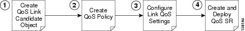
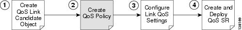
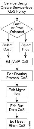
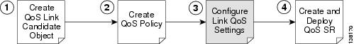
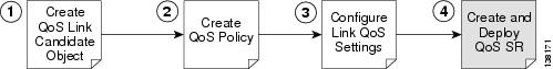
Figure 3-1 Process Flow for IP QoS Provisioning
The QoS process model in ISC is designed so that different types of users (for example, network administrators and service operators), can define different aspects of the QoS provisioning process.
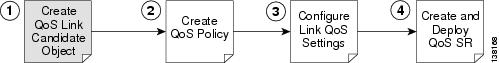
The IP QoS provisioning process in ISC is illustrated in Figure 3-1 and includes four operations:
1.
2.
3.
4.
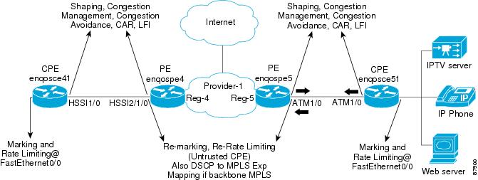
The rest of this chapter guides you through the QoS provisioning process using the ISC user interface. For each operation, a screen shot and example values for each entry field are provided. For reference, all examples in this chapter see the following network configuration (Figure 3-2).
Figure 3-2 Example of QoS Policy Deployment
Creating QoS Link Candidate Objects
Before you can provision QoS commands on a network device, you must select the device interfaces as QoS candidates. For more information on determining which device interfaces might be congestion points and might benefit from QoS provisioning, see IP QoS Provisioning Strategies.
In the ISC GUI, the process of selecting device interfaces is called defining QoS link candidates.
You can use the Service Inventory tab to identify the device interfaces to be used for QoS provisioning. The device interfaces are either link end-points or mark/rate interfaces, and when selected, these device interfaces become QoS link candidates to be used later in the QoS service request (Step 4).
For QoS provisioning, you must select both interfaces in the CE-PE link. A typical device interface selection is as follows:
•
–
–
Note
•
–
The interfaces selected as link endpoints can be provisioned with QoS parameters such as policing, traffic shaping, congestion management, congestion avoidance, link efficiency, and CAR. You apply these parameters later in the provisioning process.
This section describes how to use the ISC GUI to select device interfaces as QoS candidates and includes:
•
•
Selecting CE Device Interfaces for QoS
Typically, the service provider supplies the list of devices and interfaces to be selected for QoS provisioning. This section describes how to select device interfaces for QoS.
To select interfaces in a CE device for QoS:
Step 1
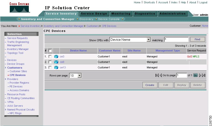
Step 2
Figure 3-3 CE Devices List
Step 3
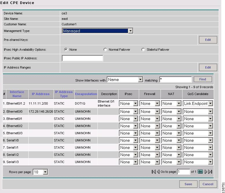
Figure 3-4 Identify CE Device Interface as QoS Candidate
Step 4
For information on the other entry fields in the Edit CPE Device window, see Cisco IP Solution Center Infrastructure Reference, 4.1.
Step 5
Note
Figure 3-5 Identify Customer-Facing LAN Interface as QoS Candidate
Step 6
Step 7
For the network example, mark CE device enqosce51 with interface ATM1/0.52 defined as the QoS Candidate Link Endpoint, and FastEthernet 0/0 as the customer-facing LAN interface to be edited for Mark/Rate Limit.
Selecting PE Device Interfaces for QoS
You must also mark the PE device in the CE-PE link for QoS provisioning. Typically, the PE device is marked for QoS parameters at the customer-facing interface.
Note
To mark a PE device:
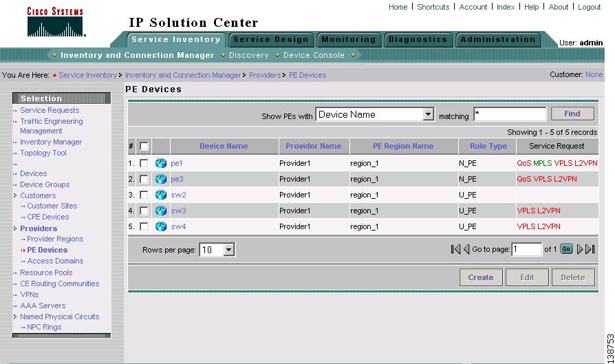
Step 1
Step 2
Figure 3-6 PE Devices List
Step 3
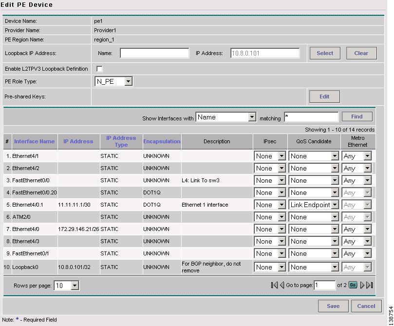
Figure 3-7 Identify PE Device Interface as QoS Candidate
Step 4
Step 5
Step 6
For the network example, mark PE device enqosce5 with interface ATM1/0.52 defined as the QoS Candidate Link Endpoint.
Creating IP QoS Policies
A QoS service policy is divided into two policy categories; service level policies and link level policies. Most networks have a combination of both policy types.
These two parts of the ISC QoS policy are managed in different parts of the user interface.
•
•
This section describes how to create a IP QoS service-level policy using the ISC GUI. The process of creating a link-level QoS Policy is described in Configuring Link-Level IP QoS Settings.
Creating the Service Level IP QoS Policy
This section describes how to create a service level IP QoS policy.
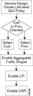
Figure 3-8 IP QoS: Create a Service Level QoS Policy
The IP QoS policy is the set of rules or conditions that apply to packets as they come across each interface that has been assigned as a link endpoint. This set of rules is defined in a QoS service class.
A typical IP QoS policy consists of at least three service classes. ISC provides, by default, five different services class templates to use or modify.
•
•
•
•
•
Select the service classes to use in the QoS policy and edit each one with the required parameters. All service classes except the Voice Class of Service require that you enter at least the bandwidth. You can also delete an unused service class, change the order of the service classes, or add another data service class, if needed.
The following sections describe how to create the service class portion of an IP QoS Policy using the ISC user interface. For detailed information on the entry fields for each service class parameter, see "IP QoS Policy Parameters.".
To create an IP QoS policy:
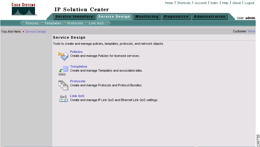
Step 1
Figure 3-9 Service Design
Step 2
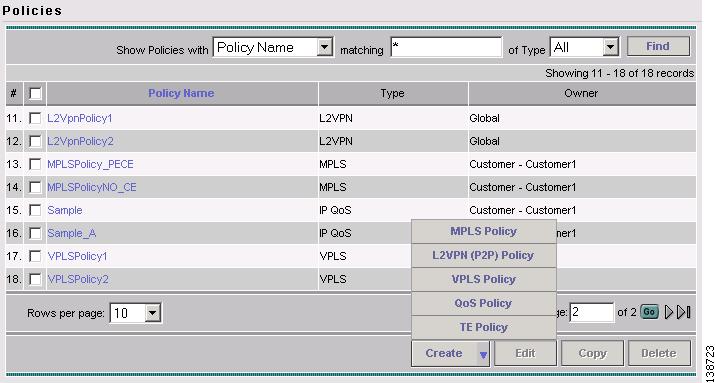
Figure 3-10 Policies
The Policies window lists all policies that currently exist for the different ISC services. Use this window to make changes to an existing policy, or to delete an unwanted service policy.
Step 3
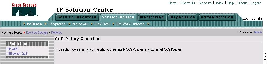
Figure 3-11 Create QoS Policy
Step 4
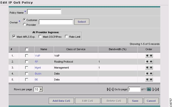
Figure 3-12 Edit IP QoS Policy
The Edit IP QoS Policy window lists the policy name, the customer or provider for this policy, and displays the five recommended default service classes. Use this window to select and edit the service classes to use in the QoS policy.
In addition to the service classes, you can re-mark or add re-rate limiting parameters to a PE device using the following check boxes.
•
•
•
Step 5
Note
Step 6
Step 7
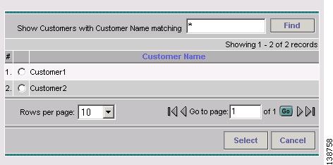
Figure 3-13 Select Customer for QoS Policy
This identifies the customer for the QoS policy. You return to the Edit IP QoS Policy window.
The next step in defining the service level QoS policy is to edit the service classes. You can apply one or more service classes to the QoS policy. Edit the default service classes provided by ISC, delete the unwanted service classes, and add a data service class if necessary. A typical QoS policy consists of 3 service classes; VoIP, Management, and a data service class, such as Best Effort.
Step 8
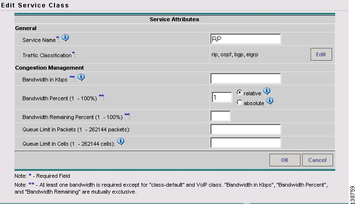
Figure 3-14 Edit Service Class—Routing Protocol
Step 9
Depending on the service class you are editing, you receive the appropriate window. For a detailed explanation of the entry fields for this service class and the windows for the other service classes, see Service Level IP QoS Parameters.
Step 10
To change the processing order of the service classes, use the up and down arrow keys on the Edit IP QoS Policy window. The service class policies are applied to the network devices in the order they are presented on the Edit IP QoS Policy window.
Step 11
Step 12
Step 13
Note
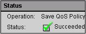
When you save an IP QoS policy, a status information box is displayed on the bottom left of the ISC window. The following examples show the different status messages and user action required, to correct any problems.
a.
Figure 3-15 Save is Successful
b.
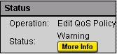
Figure 3-16 Edit QoS Policy with Warning
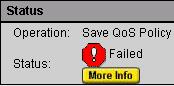
c.
Figure 3-17 Save Unsuccessful
Note
Configuring Link-Level IP QoS Settings
The second part of an ISC IP QoS policy is the link level policy, also called the link QoS setting. The link QoS setting describes the specific CE-PE link QoS parameters to use.
The link QoS setting is a group of QoS parameters that are sensitive to link bandwidth and the CE-PE link's layer 2 encapsulation type. Typically, a service provider requires several different link QoS settings, one for each link bandwidth.
Link QoS settings are associated with each link in the QoS Service Request. For each CE-PE link in the QoS service request, you can have one corresponding link QoS setting.
Link QoS Policy
Use the Link QoS policy to configure the link-specific QoS information.
Create the link QoS setting using the Link QoS operation area of the ISC GUI. The Link QoS policy allows you to create and manage the following link QoS settings:
•
Creating a Link QoS Setting
This section describes how to create a link QoS setting for a network.
Figure 3-18 Creating a Link IP QoS Setting
To create the link QoS setting:
Step 1
Figure 3-19 Service Design
Step 2
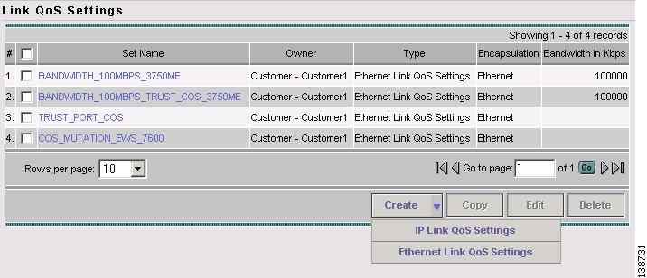
Figure 3-20 Link QoS Settings
Step 3
•
•
•
•
•
You can select an existing link QoS setting or create a new one. For the network example, create a new IP Link QoS setting.
Step 4
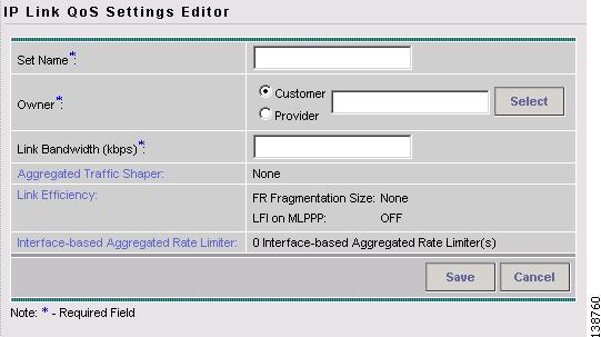
Figure 3-21 IP Link QoS Settings Editor
Step 5
Table 3-1 IP Link QoS Settings Editor Entry Field
Set Name
The name of the link QoS settings. Specify a name that describes the service offered by the settings. For example: Frame_64K_Gold; ATM_2Mb_Silver. The name Frame_64K_Gold indicates that this set should be used on a CE-PE link of bandwidth 64kbps, whose layer-2 encapsulation is Frame Relay and to meet an SLA of Gold.
Owner (Customer or Provider)
Click Select to choose from a list of customers or providers.
Link Bandwidth
This is a required field. The link bandwidth specifies the maximum amount of bandwidth allocated for packets belonging to this link.
Aggregated Traffic Shaper
Applies traffic shaping QoS parameters to the device interface. Click Aggregated Traffic Shaper to set these parameters. Use this method instead of applying traffic shaping parameters with a service class. For more information on the parameters for aggregated traffic shaping, see Aggregated Traffic Shapers.
Link Efficiency
Click Link Efficiency to set these parameters. For more information on the link efficiency parameters, see Link Efficiency Settings.
Interface-based Aggregated Rate Limiter
This provides rate limiting for the traffic on a particular interface for the CE-PE link. Click Interface-Based Aggregated Rate Limiter to set these parameters. For more information on the interface-based aggregated rate limiter parameters, see Interface-Based Aggregated Rate Limiters.
Step 6
Step 7
Step 8
Creating and Deploying IP QoS Service Requests
After both the service level and the link level QoS polices are created, the final steps in the QoS provisioning process are to create and deploy a QoS service request.
A QoS service request contains one or more QoS links. A QoS link can contain two interfaces (CE-PE link) or just one interface (CE only or PE only). Each link can optionally be associated with a QoS link setting. A QoS policy can be associated with a QoS service request.
A QoS service request should:
•
•
All QoS links in the service request can optionally be associated with a link QoS setting
To apply QoS policies to network devices, you must deploy the QoS service request.
When a QoS SR is deployed (commissioned), the provisioning engine (besides uploading the latest configs) will determine the device/linecard and IOS version associated with the target device (both CE and PEs). This information will determine the QoS feature set that is supported by the device/linecard. Armed with this feature set, a delta config is created (comparing the existing repository with the latest upload) to satisy the service request.
This section describes how to use the ISC GUI to create and deploy an IP QoS service request and includes:
•
•
Creating an IP QoS Service Request
This section describes how to create a QoS service request, independent of VPN services.
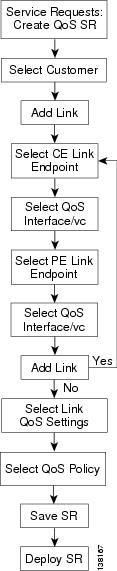
Figure 3-22 Create an IP QoS Service Request
To create a QoS service request for MPLS services, see IP QoS for MPLS VPNs.
To create an IP QoS service request:
Step 1
The Service Requests window appears. (Figure 3-23).
Figure 3-23 Service Requests List
The Service Requests window lists the current service requests.
Note
Step 2
Step 3
Figure 3-24 Select Customer
The QoS Service Editor window appears (Figure 3-25).
Figure 3-25 QoS Service Editor
The QoS Service Editor window displays the following information about each QoS links:
•
•
•
•
•
•
•
Use the QoS Service Editor window to manage CE-PE links, or to select MPLS service requests for IP QoS provisioning. You can also select link QoS settings for the CE-PE links from this window.
Note
If you add CE and PE link endpoints, you get a CE-PE QoS link. If you select link QoS settings for the CE-PE link, you get link level QoS policy. Typically, a QoS service request has both a service level policy and link level QoS settings.
Step 4
Step 5
The QoS Service Editor window displays two endpoints: CE Link Endpoint, and PE Link Endpoint. (Figure 3-26).
Figure 3-26 Select Link Endpoints
Step 6
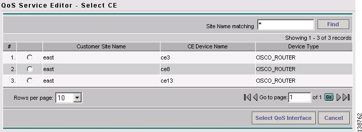
Figure 3-27 Select CE
This window lists all CE devices, including the Customer Site Name, CE device Name, and Device Type.
Step 7
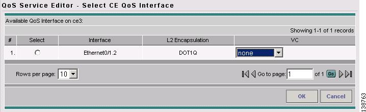
Figure 3-28 Select CE QoS Interface
This window lists the CE device interfaces identified during the Selecting CE Device Interfaces for QoS operation, and includes the following information about the CE device interfaces:
•
•
•
Step 8
Step 9
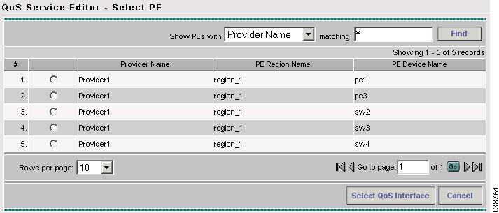
Figure 3-29 Select PE
This window lists all PE devices, including the Provider Name, Provider Region Name, and PE device Name.
Step 10
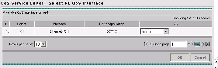
Figure 3-30 Select PE QoS Interface
This window lists the PE device interfaces identified during the Selecting PE Device Interfaces for QoS operation, and includes the following information about the PE device interfaces:
•
•
•
Step 11
Figure 3-31 QoS Service Editor with CE and PE Endpoints
The interface information for the PE link endpoint is listed.
Step 12
Step 13
Figure 3-32 Select Link QoS Settings
This window lists all set names (link QoS settings) created during the Configuring Link-Level IP QoS Settings operation.
Step 14
When you have finished adding all CE and PE Link Endpoints, the service request creation process is complete.
Step 15
Figure 3-33 QoS Service Editor with Link QoS Setting
This saves the QoS service request parameters to the ISC Repository. The ISC-generated configlet is downloaded to the network device when the service request is deployed. See the following section.
For more information on the ISC Repository, see Cisco IP Solution Center Infrastructure Reference, 4.1.
Deploying an IP QoS Service Request
To apply QoS policies to network devices, you must deploy the QoS service request. When you deploy a QoS service request, ISC generates a configlet to download to each device.
When the configlets are generated, the QoS service request enters the Pending state once the configlets have been generated and downloaded to the device(s) and the AUDIT task is in-process. When the configlets are downloaded to all the devices in the service request and the result of the AUDIT task is successful, the QoS service request enters the Deployed state.
To deploy a QoS service request:
Step 1
Figure 3-34 Deploy QoS Service Request
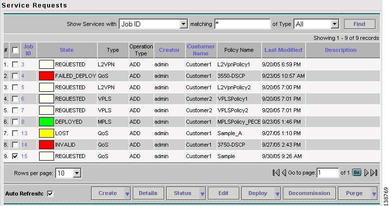
This window shows all active service requests for this user name and the following service request information: JobID, State, Type, Operation Type, Creator, Customer Name, Policy Name, Last Modified Date, and the Description.
From the Service Requests window, you can Create, view the Details, Edit, Deploy, Decommission, and Purge an active service request.
Step 2
Tip
ISC generates the QoS configlet and downloads it to the network device.
To see if a QoS service request is successfully deployed, check the State field on the Service Requests window.
Note
IP QoS for MPLS VPNs
ISC supports the following QoS parameters for MPLS VPNs:
•
•
•
The following sections describes how to apply IP QoS parameters to an MPLS service request.
Checking Prerequisites
For an MPLS network, ISC marks packets with MPLS Experimental values (MPLS Exp.) at the PE ingress interface. Before you can apply QoS parameters to an MPLS network, you must already have:
•
•
See Cisco IP Solution Center MPLS VPN User Guide, 4.1 for more information on creating MPLS service requests.
•
Creating a QoS Service Request from an MPLS Service Request
Use the following procedure to create a QoS service request from an MPLS service request:
Step 1
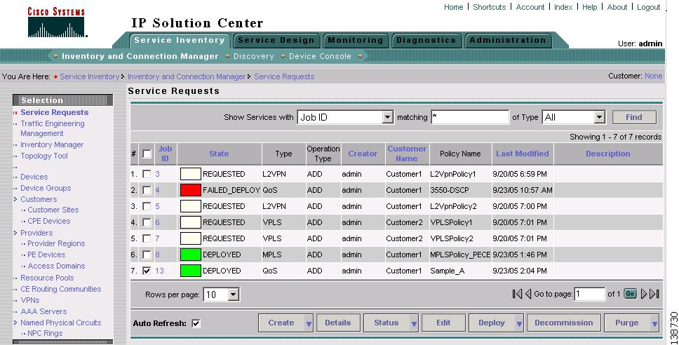
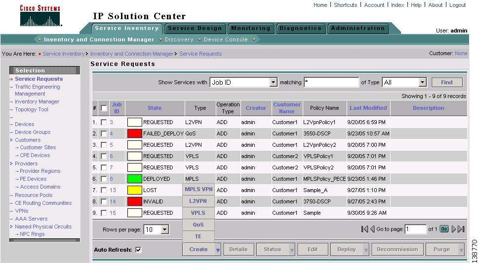
Figure 3-35 Service Requests
The Service Requests window lists the current list of service requests.
Note
Step 2
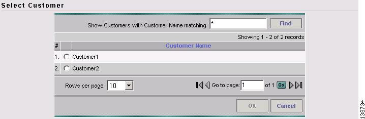
The Select Customer window appears (Figure 3-24).
Step 3
Figure 3-36 Select Customer
The QoS Service Editor window appears (Figure 3-25).
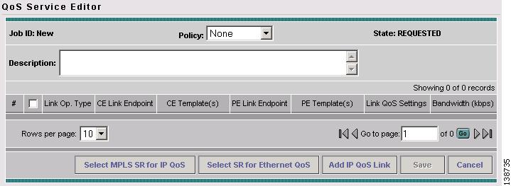
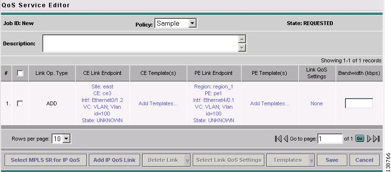
Figure 3-37 QoS Service Editor
The QoS Service Editor window displays the following information about a link:
•
•
•
•
•
•
•
Step 4
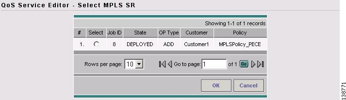
Figure 3-38 Select MPLS Service Request for QoS
This window lists existing MPLS service requests, including the deployment state, the customer, and policy name.
Step 5
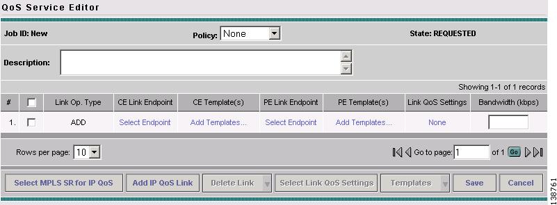
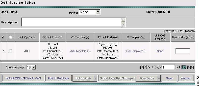
Figure 3-39 QoS Service Editor
This window lists the CE and PE links that were created during MPLS provisioning. For more information on MPLS provisioning, see Cisco IP Solution Center MPLS VPN User Guide, 4.1.
From this window you can delete or add more links and apply link QoS settings to a link endpoint pair.
Step 6
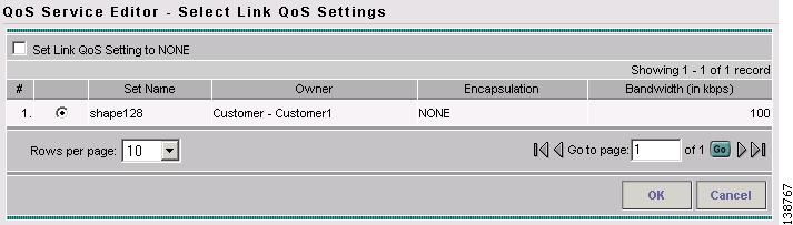
Figure 3-40 QoS Service Editor - Select Link QoS Settings
This window lists all set names (link QoS settings) previously defined in the link level QoS policy. See Configuring Link-Level IP QoS Settings for more information.
Step 7
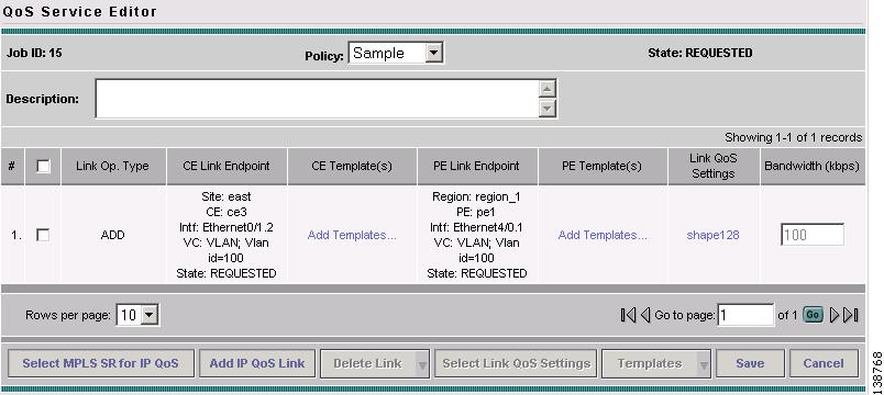
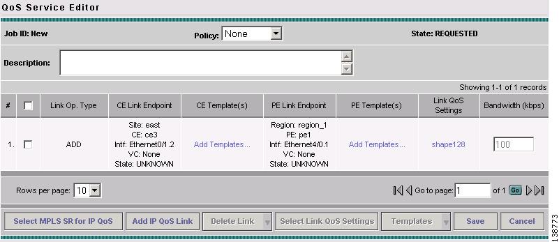
Figure 3-41 Completed QoS Service Request from MPLS Service Request
The CE-PE links and link QoS settings for the QoS service request are listed. These are the QoS parameters that will be applied to the MPLS service request.
Step 8
Step 9
When the configlets are generated and downloaded to the devices, the QoS service request enters the Pending state. When the devices are audited, the QoS service request enters the Deployed state.
Note