Feedback
Table Of Contents
How to Implement ISC QoS Effectively
Predefined Ethernet QoS Policies
MPLS Experimental Values (IP QoS)
Congestion Avoidance (IP QoS only)
Introduction
This guide describes the Cisco IP Solution Center Quality of Service (ISC QoS) product, including features, graphical user interface, and the step-by-step procedures needed to perform various QoS-related tasks.
This chapter contains the following sections:
•
How to Implement ISC QoS Effectively
Overview
When network congestion occurs, all traffic has an equal chance of being dropped. Quality of service (QoS) provisioning categorizes network traffic, prioritizes it according to its relative importance, and provides priority treatment through various techniques. Implementing QoS in your network makes network performance more predictable and bandwidth utilization more effective.
QoS classifies traffic by assigning class of service (CoS) values to frames at supported ingress interfaces. QoS implements scheduling on egress interfaces with transmit queue drop thresholds and multiple transmit queues that use CoS values to give preference to higher-priority traffic.
QoS manages bandwidth to assure the desired performance for network applications. For example, e-mail generally does not require high performance from a network, but real-time applications such as IP telephony or video streaming do. If the network is not consistently providing data flow control for these applications, the performance suffers.
Service provider network architecture contains access routers, distribution routers, core routers and ATM switches. The access routers terminate customer connections. The Cisco IP Solution Center (ISC) configures QoS at the access circuit, which involves the access router (called provider edge devices, or PEs) in the service provider network and the customer equipment (CE) in the customer network. A QoS policy is applied to the selected set of access circuits using a QoS service request.
In this document, Ethernet QoS refers to Metro Ethernet QoS, which now offers a wide array of features comparable with that of IP QoS.
There are three ways to provision QoS using ISC:
•
IP QoS provisioning is described in "Provisioning Process for IP QoS.".
•
IP QoS MPLS VPN is described in IP QoS for MPLS VPNs.
•
QoS provisioning for MPLS VPN is described in IP QoS for MPLS VPNs.
A configuration trial in a lab setting is recommended.
This chapter describes the basic concepts for QoS as it is used in the ISC application.
How to Implement ISC QoS Effectively
QoS provisioning is a method for optimizing the flow of traffic in a network. If you have an enterprise network with services facilitated across a service provider MPLS infrastructure, QoS provisioning can guarantee that all applications receive the service levels required to meet expected performance in the network.
For complete QoS implementation you should identify:
•
•
•
QoS is a collection of technologies that allows applications to request and receive predictable service levels in terms of bandwidth, latency variations, and delay.
Table 1-1 describes the typical QoS requirements for a multimedia network.
Voice and video applications are less tolerant of loss, delay, and delay variation (jitter) than data, but their QoS requirements are more obvious. Data applications vary widely in their QoS requirements, and should be profiled before you determine the appropriate classification and scheduling treatment.
QoS Components
There are three primary configuration components to IP QoS:
•
•
•
In ISC, the QoS components used to achieve classification, scheduling, and resource management are:
•
•
Each of these components is described in the following sections.
Predefined Ethernet QoS Policies
Predefined policies are only available for Ethernet QoS, not IP QoS.
The recommended way to provision Ethernet QoS using Cisco IP Solution Center is to use the predefined policies provided with Cisco IP Solution Center as a basis for new policies (if such are required).
The predefined policies correspond to typical Metro Ethernet cases on 3550, 3750-ME, and 7600 series routers. The use cases are described in "Metro Ethernet Use Cases."
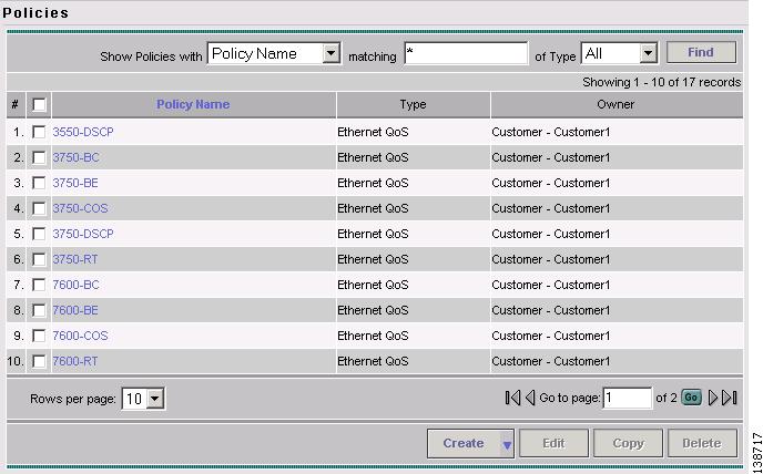
Figure 1-1 shows the predefined Ethernet QoS policies provided in the Policy Manager.
Figure 1-1 Predefined Policies in Cisco IP Solution Center
For a description of how the predefined policies are used to provision Ethernet QoS, see "Provisioning Process for Ethernet QoS."
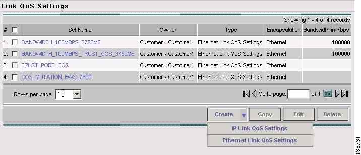
ISC QoS also offers four predefined Ethernet Link QoS policies. These are depicted in the Link QoS Settings window shown in Figure 1-2.
Figure 1-2 Link QoS Settings
For a description of how the predefined policies are used to provision Ethernet QoS, see "Provisioning Process for Ethernet QoS."
Traffic Classification
Traffic classification (also called packet classification) partitions traffic into multiple priority levels, or classes of service.
For example, using the three precedence bits in the type of service (ToS) field of the IP packet header, you can categorize packets into a limited set of up to eight traffic classes (0 through 7). After you classify packets, you can use other QoS components to assign the appropriate traffic handling policies for each traffic class.
Packets can also be classified by external sources such as by a customer, or by a downstream network provider. You can either allow the network to accept the external classification, or override it and reclassify the packet according to the Ethernet QoS policy you specify in ISC.
The differences between IP QoS and Ethernet QoS when it comes to traffic classification are described below.
IP QoS
For IP QoS, ISC allows you to classify traffic based on source address, source port, destination port, port ranges, protocol ID, DSCP, IP Precedence values, routing protocols (RIP, OSPF, BGP or EIGRP), and transport protocols (FTP, http, telnet, SMTP, TFTP, or other user defined TCP or UDP protocol number or range).
ISC uses traffic classification to associate packets with a specific Classes of Service (Voice, Data, Management, etc.).
IP QoS has a default Class of Service. If you add a new Class of Service, it is always Data. Once you delete the Management, Routing, or VoIP class of service, it cannot be readded.
ISC provides five template service classes to use for traffic classification.
•
•
•
•
•
A typical network uses three service classes in a QoS policy: a VoIP service class, a management service class (which is often combined with a routing protocol service class), and a data service class.
Ethernet QoS
For Ethernet QoS, you can classify traffic based on Class of Service (CoS), DSCP, and IP Precedence values.
ISC uses traffic classification to associate frames with a specific class of service (Routing, Business Critical, Best Effort, etc). There are no default Ethernet QoS Classes of Service.
•
•
•
For more information on traffic classification in service classes, see Service Level Ethernet QoS Policy.
Marking
Marking is a way to identify packet flows to differentiate them. Packet marking allows you to partition your network into multiple priority levels or classes of service.
For IP QoS
ISC supports marking based on the following bits in the IP QoS type of service (ToS) byte for the packet:
•
•
•
These markings can be used to identify traffic within the network, and other interfaces can match traffic based on the IP Precedence or DSCP markings. You can set up to 8 different IP Precedence markings (0 through 7) and 64 different IP DSCP markings (0 through 63).
IP Precedence and DSCP markings are used in the following QoS concepts:
•
•
•
MPLS Experimental Values (IP QoS)
Marking with the MPLS Exp. value in addition to standard IP QoS ensures the following:
•
•
•
The MPLS Exp. bit setting directs packet behavior for QoS provisioning components, congestion management and congestion avoidance. It is updated automatically (copied from upper three bits of the ToS byte).
Note
For more information on marking with the MPLS Exp. value, see MPLS Experimental Values (IP QoS).
Ethernet QoS
In Ethernet QoS, marking can be enabled to work in one of the following two mutually exclusive ways:
•
–
–
Note: You can mark packets with either DSCP or IP Precedence, but not both.–
•
IP Precedence and DSCP markings are used in the following concepts in Ethernet QoS:
•
•
Rate Limiting
Rate limiting allows you to control the maximum rate of traffic sent or received on an interface. Rate limiting is configured on the CE and PE device interfaces at the edge of the network and limits traffic into or out of the network. Traffic that falls within the rate parameters is sent, while traffic that exceeds the parameters is dropped or sent with a different priority.
Note
ISC supports class-based rate limiting and interface-based aggregated rate limiting.
•
•
•
Rate limiting parameters in ISC include:
•
•
•
For more information on configuring rate limiting IP QoS parameters in ISC, see Interface-Based Aggregated Rate Limiters.
Traffic Shaping
Traffic shaping allows you to control the traffic exiting an interface to match its flow to the speed of the remote target interface and to ensure that traffic conforms to the policies assigned to it.
ISC supports class-based traffic shaping and aggregated traffic shaping.
•
•
•
Specifying traffic shaping allows you to make better use of available bandwidth.
IP QoS traffic shaping parameters in ISC include:
•
•
•
•
–
–
–
–
–
–
–
Tip
For more information on configuring traffic shaping parameters in ISC, see Aggregated Traffic Shapers.
Congestion Management
Congestion management controls congestion by determining the order in which packets are sent out on an interface based on priorities assigned to those packets.
Congestion management involves:
•
•
•
With congestion management, packets are scheduled for transmission according to their assigned priority and the queueing mechanism configured for the interface. The router determines the order of packet transmission by controlling which packets are placed in which queue and how queues are serviced with respect to each other.
The congestion management component of QoS offers different types of queueing techniques, each of which allows you to specify creation of a different number of queues, with greater or lesser degrees of differentiation of traffic, and to specify the order in which that traffic is sent.
Congestion management parameters in ISC include:
•
•
•
Congestion management parameters are configured at the service class level in ISC. For more information, see Service Level IP QoS Parameters.
Congestion Avoidance (IP QoS only)
Congestion avoidance monitors network traffic loads in an effort to anticipate and avoid congestion at common network and internetwork bottlenecks. Congestion management parameters provide preferential treatment for priority class traffic under congestion situations, while concurrently maximizing network throughput and capacity utilization and minimizing packet loss and delay.
ISC implements congestion avoidance parameters through packet dropping methods, such as WRED. WRED is used in combination with DSCP and IP Precedence and provides buffer management. WRED is frequently used to slow down TCP flows.
Congestion avoidance parameters are configured at the service class level in ISC. For more information, see Service Level IP QoS Parameters.