Feedback
Table Of Contents
Network Architecture and Service Model
IP QoS Service Provider Network Architecture
Interface-Based Aggregated Rate Limiters
IP QoS Provisioning Strategies
Service Provider Network Architecture
Ethernet QoS Service Model Overview
Service Level Ethernet QoS Policy
Link Level Ethernet QoS Policy
Network Architecture and Service Model
A service provider network architecture contains access routers, distributed routers and core routers or ATM switches. Access routers terminate customer connections at the edge of the network.
IP QoS provisioning with the Cisco IP Solution Center (ISC) is configured on the access circuit that involves the access router (provider edge devices, or PEs) in the service provider network and the customer equipment (CEs) in the customer network.
Ethernet QoS provisioning with ISC supports a subset of the features required for the Metro Ethernet 3.1 Solution. With Ethernet QoS, ISC can deploy QoS Policies on Cisco Catalyst switches in a provider's network.
This appendix includes the following sections:
IP QoS
This section describes network architecture and service model for IP QoS in ISC.
It includes the following sections:
The section contains the following subsections:
•
IP QoS Service Provider Network Architecture
•
•
IP QoS Service Provider Network Architecture
The service provider network architecture, supported within the scope of the IP QoS provisioning model in ISC is:
•
•
•
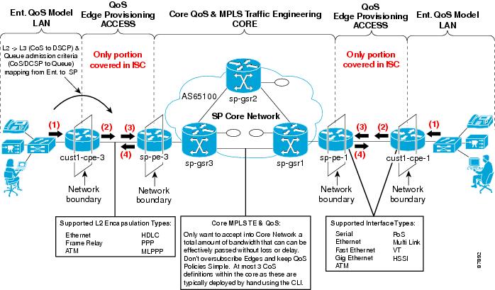
These QoS components and concepts are represented in Figure A-1.
Figure A-1 QoS Components and Concepts
IP QoS Service Model Overview
The IP QoS service model in ISC is designed so that QoS provisioning is implemented for traffic that enters the access circuit at the network edge (CE), and through the distribution portion (the CE-PE link).
This section provides an overview of the IP QoS service model in ISC.
The ISC implementation of IP QoS provisioning involves traffic through several different types of devices, link speeds, and encapsulation types. For this reason, an ISC QoS policy is divided into two categories:
•
Typically, a service provider creates three or four service classes for each QoS policy. For example, a service provider might have a platinum, gold, silver, and bronze QoS policies, and each of these policies might contain 3 service classes; a VoIP, a management, and a data service class (Best-Effort or Business-Data-1).
•
Typically, a service provider creates several link level QoS settings. For example, a service provider might create a link QoS setting for different bandwidths and encapsulation types, such as; FR_64K_gold, FR_64K_silver, FR_128K_bronze, ATM_1MBPS_gold, and Ethernet_2mbps_Silver.
ISC provides two levels of QoS policies because a QoS service request might contain one or more links with different circuit bandwidths and encapsulation types. The service level policy is designed for a type of service, like voice, but can apply to more than one link type. The link level policy is designed for different link speeds, like 1 Mbps, and can apply QoS provisioning per link.
To provision QoS parameters for devices in a service request, a network operator must:
•
•
For example, if the QoS service request is comprised of two links; a Frame Relay link with a bandwidth of 64kbps, and an ATM link, with a bandwidth of 1 mbps, and the service level agreement (SLA) purchased by the enterprise customer is the Gold policy, the following settings might be associated with the QoS service request:
–
–
–
QoS policies can either be customer-oriented or provider-oriented. Typically, service provider networks have a combination of both service level and link level QoS policies.
Service Model Components
A QoS policy is a set of parameters that control and condition the traffic flowing through a service provider network.
The Cisco IP Solution Center (ISC) configures QoS at the access circuit, which involves the PEs in the service provider network and the CEs in the customer network. A QoS policy is applied to the selected set of access circuits using a QoS service request. The ISC provisioning engine generates the QoS configuration from the service request and downloads the configuration to the specified CE and PE devices.
A QoS service request can be integrated with VPN provisioning accomplished through ISC or deployed on its own if VPN services are not provisioned through ISC.
In ISC, the IP QoS service model is comprised of:
•
•
–
–
•
Note
QoS Link Definition
A QoS Link can contain two interfaces (for both the CE and PE) or one interface (CE only or PE only). For QoS provisioning, you can select both interfaces in the CE-PE link. A typical device interface selection is as follows:
•
–
–
Note
•
–
The interfaces selected as link endpoints can be provisioned with QoS parameters such as policing, traffic shaping, congestion management, congestion avoidance, link efficiency, and CAR. You apply these parameters later in the provisioning process.
See Creating QoS Link Candidate Objects for information on defining QoS link candidate interfaces in the ISC user interface.
Service Level IP QoS Policy
The service level portion of the QoS policy corresponds to service classes. A QoS service class provides a method for classifying traffic flows into classes so that you can apply the appropriate QoS parameters to a class of traffic instead of applying them to all traffic. For example, all TCP traffic might be grouped into a single class so that bandwidth is allocated for the class and not for individual traffic flows.
A QoS service class can include:
•
•
•
•
•
•
A typical service provider network might create different QoS policies, and each QoS policy might contain three to five service classes. For example, a service provider might have a gold, silver, and bronze QoS policies, each specifying different service level agreements (SLA), and each of those QoS policies might contain one or more service classes. Most networks require at least a voice, a management, and a data service class.
ISC provides five default or template service classes for you to modify and use for a service level QoS policy:
•
•
•
•
•
See Creating the Service Level IP QoS Policy for information on defining the service level QoS policy in the ISC user interface.
The following section describes the five service classes provided with ISC.
QoS Service Classes
A QoS service class defines how each QoS parameter is applied.
Network traffic can be categorized into voice traffic, data traffic, and control traffic. Voice and data traffic are common in enterprise networks. Control traffic refers to routing protocol traffic and management traffic, which are commonly used in the service provider portion of the network.
The five default service classes provided with ISC cover most networks, which require at least one for interactive voice traffic, one for management traffic, and at least one service class for data traffic.
You can either remove or add more service classes if required. ISC supports the number of service classes defined by the Cisco differentiated services (DiffServ) architecture; up to 64 classes for DSCP traffic, and up to 8 service classes for IP Precedence traffic.
See Adding a Data Service Class for more information.
VoIP Service Class
Interactive voice traffic in ISC refers to any voice traffic (telephone calls, faxes) that is IP-encapsulated and sent over the network, such as Voice-over-IP (VoIP).
Mandatory QoS components for this service class:
•
•
•
•
Routing Protocol Service Class
Routing protocol traffic refers to traffic control messages, such as route update messages, hellos, database descriptors, keepalives, and database refresh messages. We recommended the minimum bandwidth, one percent, for your routing protocol service class.
Mandatory QoS components for this service class:
•
•
Management Service Class
Management traffic refers to the traffic between the management station at the provider core and the access routers. We recommended the minimum bandwidth, one percent, for your management service class.
Mandatory QoS components for this service class:
•
•
•
QoS parameters for the VoIP, Routing Protocol, and Management service classes are described in VoIP, Routing Protocol, and Management Service Classes.
Business-Data-1 and Best Effort Service Classes
The two data service classes, Business-Data-1 and Best Effort, are nearly identical. The only difference between them is the Traffic Classification parameter. For Business-Data-1, traffic is classified by protocol. Best-Effort classifies all traffic.
The QoS requirements for data applications can vary. Each data application should be profiled before you determine the appropriate classification and scheduling treatment.
Mandatory QoS components for this service class:
•
•
•
Optional components:
•
•
Note
QoS parameters for the Business-Data-1 and Best-Effort service classes are described in Business Data and Best Effort Service Classes.
Link Level IP QoS Policy
The link level portion of the QoS policy corresponds to QoS parameters that are sensitive to link bandwidth and the CE-PE link's encapsulation type. A link level QoS policy, called link QoS settings in the ISC user interface, provides a method for defining policies specific to the CE-PE link. For example, you might require different policies for Frame Relay and ATM links because of the different encapsulation involved.
Link level QoS parameters in ISC include:
•
•
Note
•
•
Note
Aggregated Traffic Shapers
Aggregated traffic shaping allows you to control the traffic leaving an interface. You can select an aggregated traffic shaper for each CE-PE link.
Aggregated traffic shapers are optional. ISC supports the following aggregated traffic shapers:
•
•
•
•
•
•
•
See Aggregated Traffic Shapers for more information on defining the aggregated traffic shapers parameters in the ISC user interface.
Link Efficiency
Link efficiency settings are based on the bandwidth of the CE-PE link itself and are used to minimize serialization delay on the link. ISC uses methods of fragmentation and compression to minimize this delay.
ISC supports the following link efficiency settings:
•
•
•
See Link Efficiency Settings for information on defining the link efficiency parameters in the ISC user interface.
Interface-Based Aggregated Rate Limiters
Interface-based aggregated rate limiters allow you to control the maximum rate of traffic sent or received on an interface for the CE-PE link. You can also specify traffic handling policies for when the traffic conforms or exceeds the specified rate limit.
Aggregate rate limits match all packets or a subset of packets on an interface or subinterface. To specify class-based rate limiting parameters, see Creating the Service Level IP QoS Policy.
ISC supports the following interface-based rate limiter parameters:
•
•
•
•
•
See Interface-Based Aggregated Rate Limiters for information on defining the interface-based rate limiters in the ISC user interface.
IP QoS Service Requests
An IP QoS service request contains one or more QoS links. Each link can optionally be associated with a link QoS setting. A QoS policy can be associated with a QoS service request.
An IP QoS service request should:
•
•
To apply IP QoS policies to network devices, you must deploy the QoS service request. When you deploy a QoS service request, ISC compares the device information in the Repository (the ISC database) with the current device configuration and generates a configlet.
See Creating an IP QoS Service Request for information on creating the QoS service request using the ISC user interface.
See Cisco IP Solution Center Infrastructure Reference, 4.0 for more information on the ISC Repository.
IP QoS Provisioning Strategies
ISC configures IP QoS at the access circuit, which involves the PE devices in the service provider network and the CE devices in the customer network. A QoS policy is applied to the selected set of access circuits using a QoS service request.
Typically, the points of congestion in the access circuit are:
•
•
This section describes a QoS provisioning strategy: where the congestion points in the network might be, where to apply QoS parameters, and which QoS provisioning components to use.
Managed CE Scenario
A managed CE scenario occurs when the CE is owned and managed by the service provider. In this network scenario, you can either apply QoS provisioning for the CE only or for both the CE and PE.
This section describes QoS provisioning strategies for both CE only and CE-PE scenarios.
Managed CE Only
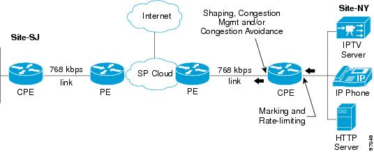
Figure A-2 illustrates a network where QoS provisioning is configured only for the managed CE device.
Figure A-2 Managed CE Scenario
In this QoS provisioning scenario:
•
•
Managed CE and PE
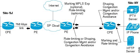
Figure A-3 illustrates a network where QoS provisioning is configured for both the managed CE and the PE device.
Figure A-3 Managed CE and PE Scenario
In this QoS provisioning scenario:
•
•
•
Unmanaged CE Scenario
An unmanaged CE scenario occurs when the CE is not owned by the service provider, but ISC is aware of the device configuration and interface information. This information must be provided by the owner of the CE device.
In this QoS provisioning scenario:
•
See Cisco IP Solution Center Infrastructure Reference, 4.0 for more information on manually creating CE devices.
•
See Creating the Service Level IP QoS Policy for more information.
PE Only Scenario
For a PE only scenario, the service provider's enterprise customer is responsible for applying the QoS configuration at the CE interfaces.
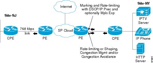
Figure A-4 PE Only Scenario
In this QoS provisioning scenario:
•
•
See "Provisioning Process for IP QoS," for more information on the QoS provisioning process.
Ethernet QoS
This section describes network architecture and service model for Ethernet QoS in ISC.
It includes the following sections:
•
•
•
•
Service Provider Network Architecture
In the Ethernet QoS implementation of ISC, the 3750-ME and 7600 devices can fulfill different roles as shown in Figure A-5.
Figure A-5 ISC Ethernet Network Diagram
The traffic flow is from the CE switches towards the MPLS/IP core. In general, QoS will be applied to the UNI interfaces for the ingress direction.
An exception hereto is UNI-NNI traffic on the 3750 ME switch. In this case, the policies would be situated on the enhanced ES ports on the egress direction.
Ethernet QoS Service Model Overview
Provisioning with Ethernet QoS involves traffic through several different types of devices, link speeds, and encapsulation types. For this reason, an ISC QoS policy is divided into two categories:
–
–
The Ethernet QoS service model in ISC is implemented for traffic that enters the User Network Interface(UNI) and either goes out to the Network-to-Network Interface(NNI) or is switched locally within the U-PE.
Ethernet QoS policies correspond to Ethernet QoS service classes. Each QoS service class provides a method to classify, mark, condition, queue, and schedule traffic based on specified criteria, such as Class of Service, VLAN ID, etc.
A typical service provider network might create different QoS policies, and each QoS policy might contain three to four service classes. For example, a service provider might have gold, silver, and bronze QoS policies, each specifying different service level agreements (SLA), and each of those QoS policies might contain one or more service classes. Most networks require at least a voice and a data service class.
To provision Ethernet QoS parameters for devices in a service request, a network operator must:
•
•
•
•
•
•
•
•
•
Ethernet QoS policies can either be customer-owned or provider-owned.
For more information on the Ethernet QoS service model, see "Provisioning Process for Ethernet QoS."
QoS Link Definition
An Ethernet QoS Link can contain two interfaces (for both the U-PE and N-PE) or one interface (U-PE only or N-PE only). For Ethernet QoS provisioning, you can select both interfaces. A typical device interface selection is as follows:
For the U-PE device:
•
•
Service Model Components
In ISC, the Ethernet QoS service model is comprised of:
•
•
–
–
•
Figure A-6 shows a high-level view of an Ethernet network, sometimes referred to as a Metro Ethernet network, where ISC is used to apply Ethernet QoS.
Figure A-6 ISC Ethernet Network Diagram
Terminology
To understand the Ethernet QoS service model used in ISC, one needs to be familiar with the following terminology.
Devices
The following device types are used in Ethernet QoS for ISC:
•
•
•
•
Interfaces
The following interface types are used in Ethernet QoS for ISC:
•
•
•
•
Service Definitions
Following the MEF (Metro Ethernet Forum) approach, the services that comprise the Metro Ethernet 3.1 solution can be classified into two general categories:
•
•
In the MEF terminology this maps to the following Ethernet service types:
•
•
Within these two service types, Metro Ethernet services can be created by assigning values to a set of attributes grouped according to:
•
•
Service Level Ethernet QoS Policy
The service level portion of the QoS policy corresponds to service classes. A QoS service class provides a method for classifying traffic flows into classes so that you can apply the appropriate QoS parameters to a class of traffic instead of applying them to all traffic. For example, all TCP traffic might be grouped into a single class so that bandwidth is allocated for the class and not for individual traffic flows.
A QoS service class can include:
•
•
•
•
A typical service provider network might create different QoS policies, and each QoS policy might contain three to five service classes. For example, a service provider might have a gold, silver, and bronze QoS policies, each specifying different service level agreements (SLA), and each of those QoS policies might contain one or more service classes.
You can create real time, business critical, and best effort classes, etc., within a policy.
See Creating Ethernet QoS Policies, for information on defining the service level Ethernet QoS policy in the ISC user interface.
Link Level Ethernet QoS Policy
The link level portion of the QoS policy corresponds to QoS parameters that are sensitive to link bandwidth and the UNI's encapsulation type. A link level QoS policy, called link QoS settings in the ISC user interface, provides a method for defining link-specific policies. For example, you might require different policies for Frame Relay and ATM links because of the different encapsulation involved.
Link level QoS parameters in ISC include:
•
•
•
•
Ethernet QoS Service Requests
An Ethernet QoS service request contains one or more QoS links. Each link can optionally be associated with a link QoS setting. A QoS policy can be associated with a QoS service request.
An Ethernet QoS service request should:
•
•
To apply Ethernet QoS policies to network devices, you must deploy the QoS service request. When you deploy a QoS service request, ISC compares the device information in the Repository (the ISC database) with the current device configuration and generates a configlet.
See Creating an Ethernet QoS Service Request for information on creating the QoS service request using the ISC user interface.
See Cisco IP Solution Center Infrastructure Reference, 4.1 for more information on the ISC Repository.