Feedback
Table Of Contents
Provisioning Process for Ethernet QoS
Creating an L2VPN Service Request
Creating Ethernet QoS Policies
Creating an Ethernet QoS Policy
Configuring Link-Level Ethernet QoS Settings
Creating and Deploying Ethernet QoS Service Requests
Creating an Ethernet QoS Service Request
Deploying an Ethernet QoS Service Request
Provisioning Process for Ethernet QoS
This chapter describes the steps required to provision Ethernet QoS for a network using the Cisco IP Solution Center (ISC) graphical user interfaces.
Before starting the provisioning process, be sure to read "Getting Started."
This chapter describes how to set up Ethernet QoS provisioning for L2VPN and VPLS.
The chapter contains the following sections:
•
Creating an L2VPN Service Request
•
•
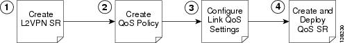
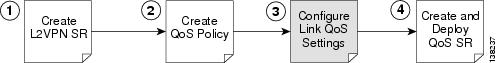
Ethernet QoS Process Model
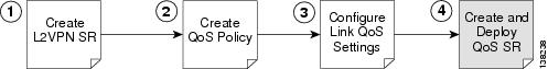
The Ethernet QoS process model in ISC is designed so that different types of users (for example, network administrators and service operators), can define different aspects of the QoS provisioning process.
The Ethernet QoS provisioning process shown above includes four operations:
1.
2.
3.
4.
Creating an L2VPN Service Request
The first step in provisioning Ethernet QoS is to create an L2VPN service request. This is needed because an Ethernet QoS service request is created by importing an L2VPN service request into a QoS service request.
To create an L2VPN service request, see Cisco IP Solution Center L2VPN User Guide, 4.1.
Creating Ethernet QoS Policies
A QoS service policy is divided into two policy categories; service level policies and link level policies. Most networks have a combination of both policy types.
These two parts of the ISC QoS policy are managed in different parts of the user interface.
•
•
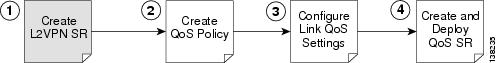
This section describes how to create an Ethernet QoS service-level policy using the ISC GUI. The process of creating a link-level QoS Policy is described in Configuring Link-Level Ethernet QoS Settings.
Figure 4-1 Create a Service-Level Ethernet QoS Policy
Creating an Ethernet QoS Policy
ISC provides a selection of predefined Ethernet QoS policies that in most cases can be used as a basis for new policies. It is recommended that this option be used whenever possible.
However, if none of the predefined policies available prove suitable, a new policy can be created from scratch (see Step 2 in the following procedure).
To create an Ethernet QoS policy using predefined policies:
Step 1
Figure 4-2 Policies
The Policies window appears (Figure 4-3).
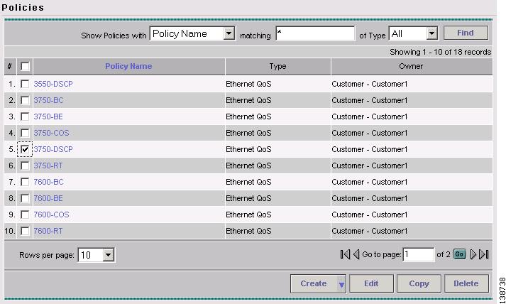
Figure 4-3 Predefined Policies
The Policies window lists all policies that currently exist for the different ISC services. The ones listed in Figure 4-3 are the ten predefined Ethernet QoS policies supplied with ISC. See "Metro Ethernet Use Cases" for at description of the corresponding use cases and hardware platforms.
Note
Step 2
Select the predefined policy that most closely match your needs and click Copy.
The Edit Ethernet QoS Policy window appears (Figure 4-4).
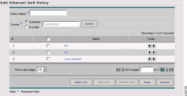
Figure 4-4 Edit Ethernet QoS Policy
The Edit Ethernet QoS Policy window lists the policy name, the owner (customer or provider) for this policy, and any existing service classes tied to it. Use this window to add, delete, or edit service classes for the Ethernet QoS policy.
Step 3
Note
Step 4
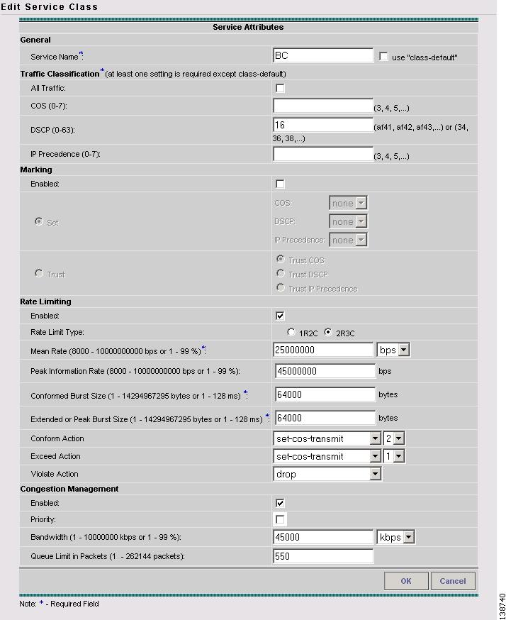
The Edit Service Class window appears (Figure 4-5).
Figure 4-5 Edit Service Class
For a detailed explanation of Edit Service Class parameters, see "Ethernet QoS Policy Parameters." .
Step 5
Step 6
To change the processing order of the service classes, use the up and down arrow keys on the Edit Ethernet QoS Policy window. The processing order dictates the order in which the class-maps are applied to the policy map and subsequently the order in which they are processed.
Step 7
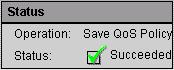
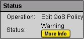
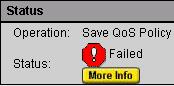
When you save an Ethernet QoS policy, a status information box is displayed on the bottom left of the ISC window. The following examples show the different status messages and user action required, to correct any problems.
a.
Figure 4-6 Save is Successful
b.
Figure 4-7 Edit QoS Policy with Warning
c.
Figure 4-8 Save Unsuccessful
Note
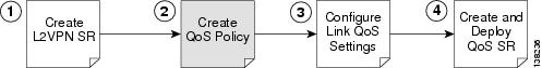
Configuring Link-Level Ethernet QoS Settings
The second part of an ISC Ethernet QoS policy is the link level policy, also called the link QoS setting. The link QoS setting describes the specific UNI and VLAN level QoS parameters to use.
Link QoS settings are associated with each link in the QoS Service Request.
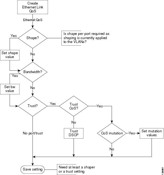
Creating a Link QoS Setting
This section describes how to create a link QoS setting for a network.
Figure 4-9 Create a Link Ethernet QoS Setting
To create the link QoS setting:
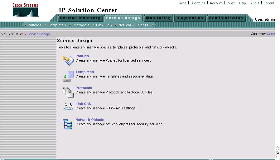
Step 1
Figure 4-10 Service Design
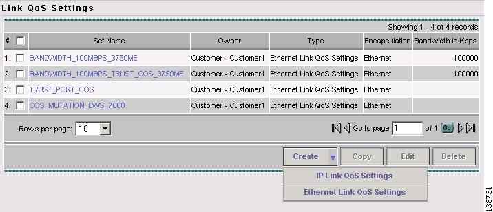
The Link QoS Settings window appears (Figure 4-11).
The four Link QoS names listed in Figure 4-3 are the four predefined Ethernet Link QoS policies supplied with ISC.
Figure 4-11 Link QoS Settings
Step 2
You can also create a policy from scratch and this is described in the following.
Click Create to open a drop-down menu with two options, IP Link QoS Settings and Ethernet Link QoS Settings. Select the Ethernet Link QoS Settings to create an Ethernet Link QoS.
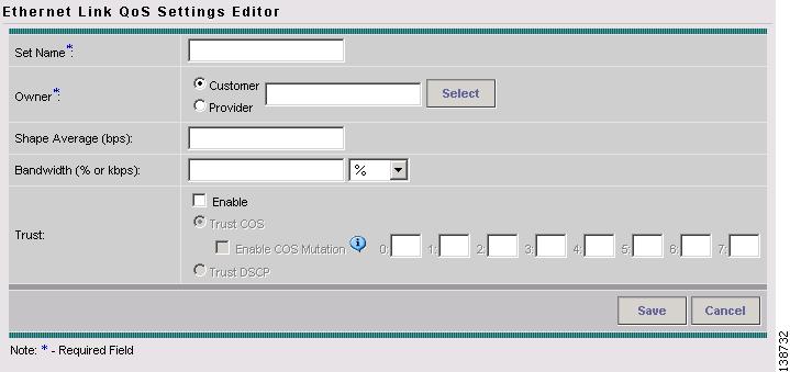
The Ethernet Link QoS Settings window appears (Figure 4-12).
Figure 4-12 Ethernet Link QoS Settings Editor
Step 3
Add the desired settings. An explanation of the link QoS setting parameters is provided in "Ethernet QoS Policy Parameters."
Step 4
Creating and Deploying Ethernet QoS Service Requests
After both the service level and the link level QoS polices are created, the final steps in the QoS provisioning process are to create and deploy a QoS service request.
A QoS service request contains one or more QoS links. A QoS link can contain two interfaces or just one interface. Each link can optionally be associated with a QoS link setting. A QoS policy can be associated with a QoS service request.
A QoS service request should:
•
•
All QoS links in the service request can optionally be associated with a link QoS setting.
To apply QoS policies to network devices, you must deploy the QoS service request. When you deploy a QoS service request, ISC compares the device information in the Repository (the ISC database) with the current device configuration and generates a configlet.
This section describes how to use the ISC GUI to create and deploy an Ethernet QoS service request and includes the following sections:
•
•
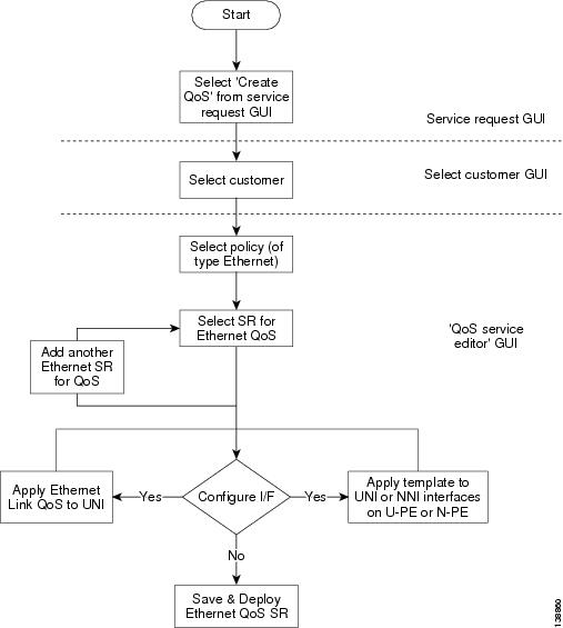
Creating an Ethernet QoS Service Request
This section describes how to create an Ethernet QoS service request, independent of VPN services.
Figure 4-13 Create an Ethernet QoS Service Request
To create an Ethernet QoS service request:
Step 1
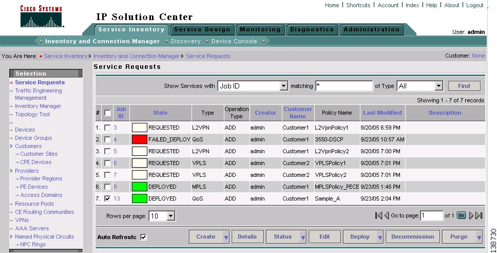
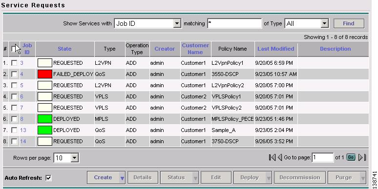
The Service Requests window appears. (Figure 4-14).
Figure 4-14 Service Requests
The Service Requests window lists the current service requests.
Note
Step 2
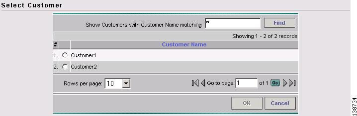
Step 3
Figure 4-15 Select Customer
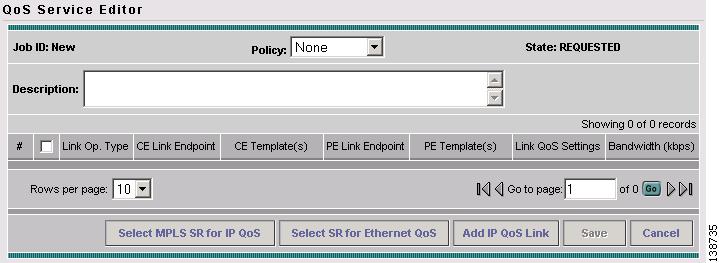
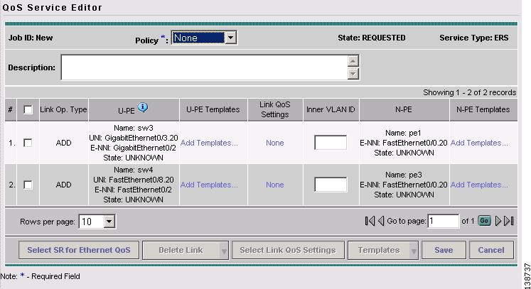
The QoS Service Editor window appears (Figure 4-16).
Figure 4-16 Default QoS Service Editor
Step 4
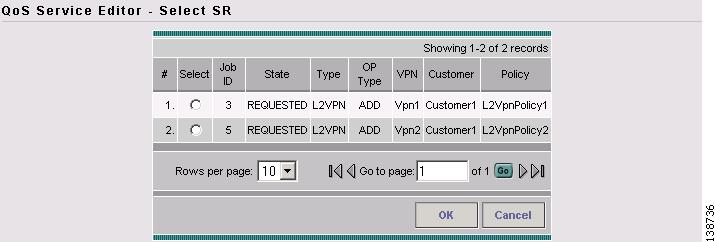
The QoS Service Editor window displays the available service requests (Figure 4-17).
Figure 4-17 Select Service Request
Step 5
Figure 4-18 QoS Service Editor - Ethernet QoS Service Request Mode
This window lists the link information for the selected service requests.
The QoS Service Editor window displays the following information about each QoS link:
•
•
•
•
•
•
•
Use the QoS Service Editor window to select a service request for Ethernet QoS provisioning.
Step 6
Step 7
Step 8
Step 9
The newly created QoS service request now appears in the Service Requests window (Figure 4-19).
Figure 4-19 Service Requests with Newly Added QoS Service Request
This saves the QoS service request parameters to the ISC Repository. The ISC-generated configlet is uploaded to the network device when the service request is deployed. This step is described in the following section.
For more information on the ISC Repository, see Cisco IP Solution Center Infrastructure Reference, 4.1.
Deploying an Ethernet QoS Service Request
To apply QoS policies to network devices, you must deploy the QoS service request. When you deploy a QoS service request, ISC generates a configlet to download to each device.
When the configlets are generated, the QoS service request enters the Pending state. When the configlets are uploaded to all the devices in the service request, the QoS service request enters the Deployed state.
To deploy a QoS service request:
Step 1
Figure 4-20 Deploy QoS Service Request
This window shows all active service requests for this user name and specific service request information.
From the Service Requests window, you can Create, view the Details, view the Status of SR Links or Logs, Edit, Deploy, Decommission, and Purge an active service request.
Step 2
Tip
ISC generates the QoS configlet and downloads it to the network device.
To see if a QoS service request has been successfully deployed, check the State field on the Service Requests window.
Note
Inner VLAN for 3750-ME
This section describes L2VPN EWS/VPLS classification on outer and inner VLAN. (See General Metro Ethernet Service Types for a definition of Metro Ethernet terminology.)
This QoS model based on inner C-VLAN ID classification is only found in Catalyst 3750-ME. Therefore it is not part of the mainstream ME3.1 solution, although this fact does not restrict its use.
With this approach, one could create a H-QoS policy that matches on two VLAN ID values (outer and inner) and then also look at the inner CoS or even DSCP information within that outer/inner VLAN combination.
Note
Note
The following CLI shows how inner and outer VLAN is specified in a class-map.
class-map match-all rtvlan_102
match vlan 108
match vlan inner 102
!
class-map match-all bcvlan_104
match vlan 108
match vlan inner 104
!
class-map match-all bevlan_108
match vlan 108
!
policy-map RT_VLAN_102
class match_any
police cir 30000000 bc 64000 pir 30000000 be 64000 conform-action set-cos-transmit 5
exceed-action drop violate-action-drop
priority
!
policy-map BC_VLAN_104
class class-default
police cir 20000000 bc 64000 pir 40000000 be 64000 conform-action set-cos-transmit
2 exceed-action set-cos-transmit 1 violate-action drop
bandwidth 40000
queue-limit 550
!
policy-map BE_VLAN_108
class class-default
set cos 0
bandwidth 30000
queue-limit 3
!
policy-map VLAN_Outbound
class rtvlan_102
bandwidth 30000
service-policy RT_VLAN_102
class bcvlan_104
bandwidth 40000
service-policy BC_VLAN_104
class bevlan_108
bandwidth 30000
service-policy BE_VLAN_108
!
policy-map ES_Port_Outbound
class class-default