Cisco IP Solution Center Quality of Service User Guide, 4.0
Managing and Auditing Service Requests

Table Of Contents

Managing and Auditing Service Requests

QoS Configuration Auditing

QoS Service Requests

Managing QoS Service Requests

Verifying QoS Service Requests

Service Request States

Changing Service Request Parameters

Viewing QoS Service Request Details

Links

History

Configlets

QoS Task Logs


Managing and Auditing Service Requests


Each time a QoS service request is deployed in the Cisco IP Solution Center (ISC), a configuration audit occurs. You can view the results of these in QoS configuration audit reports. Use configuration audits and reports to verify that the ISC generated configlet represents the correct QoS configuration to download to the network device.

This chapter describes how to generate and view a configuration audit, how to manage QoS service requests, and how to access task logs.

The chapter includes the following sections:

QoS Configuration Auditing

QoS Service Requests

QoS Task Logs

QoS Configuration Auditing

A configuration audit occurs automatically each time you deploy a QoS service request. During this configuration audit, ISC verifies that all Cisco IOS commands are present and that they have the correct syntax. An audit also verifies that there were no errors during deployment.

The configuration audit verifies the service request deployment by examining the commands configured by the QoS service request on the target devices. If the device configuration does not match what is defined in the service request, the audit flags a warning and sets the service request to a Failed Audit or Lost state.

You can create audit reports for new or existing QoS service requests.

Audit new services—This type of audit is for service requests that have just been deployed. This type of audit identifies problems with the configuration files downloaded to the devices.

Audit existing services—This type of audit checks and evaluates the configuration of deployed service requests to see if the service request is still in effect.

We recommend that you schedule a service request audit on a regular basis to verify the state of the network provisioning requests.

This section describes how to manually generate a configuration audit and view the audit report.

To manually generate a configuration audit:


Step 1 Select Service Inventory > Inventory and Connection Manager > Service Requests.

Step 2 Select a QoS service request for the configuration audit and click Details. The Service Request Details window appears as shown in Figure 8-1.

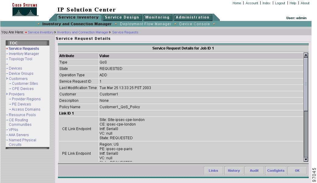
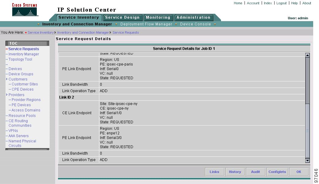
Figure 8-1 Service Request Details

Step 3 Click Audit. The Service Request Audit Report window appears. Figure 8-2 shows an example of a successful configuration audit.

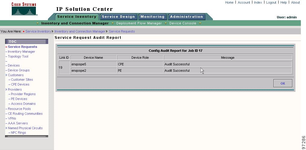
Figure 8-2 Service Request Audit Report—Successful

This window shows the device name and role, and a message regarding the status of your configuration audit.

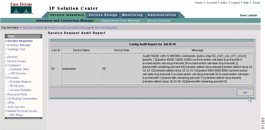
If the audit is unsuccessful, the message field shows details on the failed audit. Figure 8-3 shows an example of a failed audit message for a QoS service request.

Figure 8-3 Service Request Audit Report—Failed

The audit failure message indicates missing commands and configuration issues. Carefully review the information in the message field. If the audit fails, you must correct all errors and redeploy the service request.

Step 4 Click OK to return to the Service Request Details window.


QoS Service Requests

A QoS service request contains one or more QoS links. Each link can optionally be associated with a QoS link setting. A QoS policy can be associated with a QoS service request.

A QoS service request should:

Contain a QoS policy

Contain one or more QoS links

All links in the service request can be associated with a QoS link setting

To apply QoS policies to network devices, you must deploy the QoS service request. When you deploy a QoS service request, ISC compares the device information in the Repository (the ISC database) with the current device configuration and generates a configlet.

Use a QoS service request to apply a QoS policy to a network or to an existing L2VPN, MPLS, or VPLS service request.

The following sections describe:

Managing QoS Service Requests

Verifying QoS Service Requests

Service Request States

Service Request States

Changing Service Request Parameters


Note See Creating the QoS Service Request and Deploying the QoS Service Request for more information on the create and deploy operations.


Managing QoS Service Requests

To manage QoS service request, select Service Inventory > Inventory and Connection Manager > Service Requests.

From the Service Requests window you can perform the following operations for QoS service requests:

Create

View Details

Edit

Deploy

Decommission

Purge

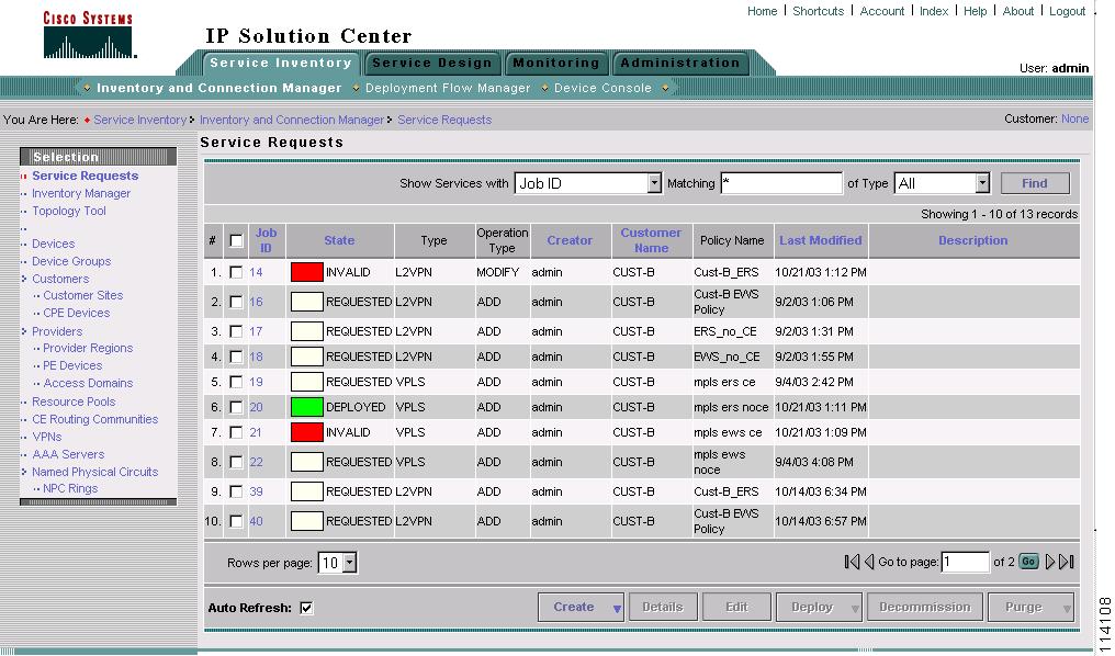
Figure 8-4 shows an example of the Service Requests window.

Figure 8-4 Service Requests List

The Service Requests window shows the current list of service requests for this user name. The list includes the following information about each service request:

JobID—The job number assigned to the service request by ISC. Table 8-1 describes ISC service request states.

State—The transition state for the service request. See Service Request States for more information.

Type—The type of service request. For example, QoS, MPLS, IPsec, L2VPN, NAT, or Firewall. - IPsec, NAT, and Firewall are not supported in this release. -

Operation Type—The operation type for the service request. For example, ADD means that you are adding this service request, and DELETE means that you are decommissioning this service request.

Creator—Username identity of person who created or last modified the service request.

Customer Name—Customer name for the service request.

Policy Name—Name of policy assigned to this service request.

Last Modified—Date and time the service request was created or last modified.

Description—Optional text description of the service request.

Verifying QoS Service Requests

After you deploy a QoS service request, you should verify that there were no errors.

You can verify a QoS service request through the following:

Transition state—The transition state of a QoS service request is listed on the Service Requests window in the State column. See Service Request States for more information.

View service request details—From the Service Requests Details window, you can view the QoS link endpoints and the QoS configlets for this service request. See Changing Service Request Parameters for more information.

Task Logs—Access the task logs from the Monitoring tab to help you troubleshoot a failed service request or to view more details about a service request. See QoS Task Logs for more information.

Service Request States

A service request transition state describes the different stages a service request enters during the QoS provisioning process.

For example, when you deploy a QoS service request, ISC compares the device information in the Repository (the ISC database) with the current device configuration and generates a QoS configlet for each device. When the configlets are generated and downloaded to the devices, the QoS service request enters the Pending state. When the devices are audited, the QoS service request enters the Deployed state.

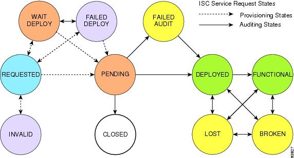
Table 8-1 describes the transition states for an ISC service request.

Table 8-1 Cisco IP Solution Center Service Request States 

Service Request Type
Description

Requested

If the service is newly entered and not yet deployed, it is not an error. However, if a Deploy is done and it remains Requested, the service is in an error state.

Invalid

Invalid indicates that the service request information is incorrect in some way. A service request moves to Invalid if the request was either internally inconsistent or not consistent with the rest of the existing network/router configurations (for example, no more interfaces were available on the router). The provisioning engine cannot generate configuration updates to service this request.

Pending

A service request moves to Pending when the Provisioning Driver determines that the request looks consistent and was able to generate the required configuration updates for this request. Pending indicates that the service request has generated the configuration updates and the configuration updates are successfully downloaded to the routers.

The Auditor regards pending service requests as new requests and begins the audit. If the service has been freshly provisioned and not yet audited, it is not an error (pending audit). However, if an audit is performed and the service is still pending, it is in an error state.

Failed Deploy

The cause for a Failed Deploy status is that DCS reports that either the upload of the initial configuration file from the routers failed or the download of the configuration update to the routers failed (due to lost connection, faulty password, and so on).

Wait Deploy

This service request state pertains only when downloading configlets to a Cisco CNS-CE server, such as a Cisco CNS IE2100 appliance. Wait Deploy indicates that the configlet has been generated, but it has not been downloaded to the Cisco CNS-CE server because the device is not currently online. The configlet is staged in the repository until such time as the Cisco CNS-CE server notifies ISC that it is up. Configlets in the Wait Deploy state are then downloaded to the Cisco CNS-CE server.

Failed Audit

This state indicates that ISC downloaded the configlet to the router successfully, but the service request did not pass the audit. Therefore, the service did not move to the Deployed state. The Failed Audit state is initiated from the Pending state. Once a service request is deployed successfully, it cannot re-enter the Failed Audit state (except if the service request is redeployed).

Deployed

A service request moves to Deployed if the intention of the service request is found in the router configuration file. Deployed indicates that the configuration file has been downloaded to the router, and the intent of the request has been verified at the configuration level. That is, ISC downloaded the configlets to the routers and the service request passed the audit process.

Lost

A service request moves to Lost when the Auditor cannot find a configuration-level verification of intent in the router configuration files. The service request was in the Deployed state, but now some or all router configuration information is missing. A service request can move to the Lost state only when the service request had been Deployed.

Functional

(does not apply to QoS service requests)

An MPLS service request moves to Functional when the auditor finds the VPN routing and forwarding tables (VRF) for this service and they match with the service intent. This state requires that both the configuration file audit and the routing audit are successful.

An IPsec service request moves to Functional when the auditor finds that the router is configured properly and the IPsec traffic is flowing (ping is used to determine if IPsec traffic is flowing). - IPsec is not supported in this release. -

Broken

(does not apply to QoS service requests)

The router is correctly configured but the service is unavailable (due to a broken cable or Layer 2 problem, for example).

An MPLS service request moves to Broken if the auditor finds the routing and forwarding tables for this service, but they do not match the service intent.

An IPsec service request moves to Broken if a ping fails for all the remote peers of the current device. - IPsec is not supported in this release. -

Closed

A service request moves to Closed if the service request should no longer be used during the provisioning or auditing process. A service request moves to the Closed state only upon successful audit of a decommission service request. ISC does not remove a service request from the database to allow for extended auditing. Only a specific administrator purge action results in service requests being removed.


Figure 8-5 illustrates which service request states relate to the QoS configuration auditing process, and which states relate to the provisioning process.

Figure 8-5 Service Requests States

Changing Service Request Parameters

You can change the QoS parameters associated with a deployed service request without decommissioning the service. For example, you might want to change a configuration to increase the bandwidth on the UNI interface.

To change the parameters, use the following procedure:


Step 1 Create a new QoS policy that represents the new level of service.

Step 2 Select the existing QoS service and edit that service request.

Step 3 Select the new policy (created in Step 1) and save the service request.

The QoS service request goes from deployed state to requested state with the new QoS policy displayed.

Step 4 Deploy the QoS service request.


The provisioning engine first removes the replaced policy parameters and immediately replaces them with the new policy parameters (see the following configlet).

interface Vlan201
  no service-policy input isc_in_Customer_A_Default_GE2/1.201
  no shutdown
!
no policy-map isc_in_Customer_A_Default_GE2/1.201
!
no class-map match-all Customer_ADefault_EFFORTGE2/1.201vlan201
!
no class-map match-all Customer_ADefaultRITICALGE2/1.201vlan201
!
no class-map match-all Customer_ADefaultAVVIDGE2/1.201vlan201
!
no class-map match-all Customer_ADefaultCONTROLGE2/1.201vlan201
!
class-map match-all Customer_Adefault2AVVIDGE2/1.201vlan201
  match ip precedence 5
!
class-map match-all Customer_Adefault2ONTROLGE2/1.201vlan201
  match ip precedence 3
!
class-map match-all Customer_Adefault2ITICALGE2/1.201vlan201
  match ip precedence 2
!
class-map match-all Customer_Adefault2EFFORTGE2/1.201vlan201
  match ip precedence 0 1 2 3 4 5 6 7
!
policy-map isc_in_Customer_A_default2_GE2/1.201
  class Customer_Adefault2AVVIDGE2/1.201vlan201
    set ip precedence 5
    police 40000 bps 40000 byte conform-action transmit exceed-action drop
  class Customer_Adefault2ONTROLGE2/1.201vlan201
    set ip precedence 3
    police 40001 bps 40001 byte conform-action transmit exceed-action drop
  class Customer_Adefault2ITICALGE2/1.201vlan201
    set ip precedence 2
    police 40002 bps 40002 byte conform-action transmit exceed-action drop
  class Customer_Adefault2EFFORTGE2/1.201vlan201
    set ip precedence 0
    police 40003 bps 40003 byte conform-action transmit exceed-action drop
!
interface Vlan201
  service-policy input isc_in_Customer_A_default2_GE2/1.201
!


Note The policy parameters that were not changed (congestion management parameters in this case (tx-queue statements) are not removed, as shown in the following configlet.


interface GigabitEthernet2/1
  tx-queue 3
    bandwidth 16000 bps
    priority high
  tx-queue 4
    bandwidth 16001 bps
  tx-queue 2
    bandwidth 16002 bps
  tx-queue 1
    bandwidth 16003 bps
!
interface Vlan201
  no shutdown
!

Viewing QoS Service Request Details

The QoS service request details include the link endpoints for the QoS service request, the history, and the QoS configlet generated during the service request deployment operation. Use the service request details to help you troubleshoot a problem or error with the service request or to check the QoS commands in the configlet.

This section describes how to view the details of a QoS service request, including the history, link details, and QoS configlets.

To view QoS service request details:


Step 1 Select Service Inventory > Inventory and Connection Manager > Service Requests.

Step 2 Select the QoS service request and click Details. The Service Request Details window appears as shown in Figure 8-6. See Figure 8-6 for Attribute details and Figure 8-7 for Link ID details.

Figure 8-6 QoS Service Request Details—Attributes

The service request attribute details include the type, transition state, operation type, ID, modification history, customer, and policy name.

Figure 8-7 QoS Service Request Details—Link ID

The service request link ID details include the link endpoints, link bandwidth and link operation type.

From the Service Request Details page, you can view more information about:

Links—The link endpoint details.

History—Service request history report

Audit—Audit reports for the link IDs

Configlets—View the ISC generated configlet for the QoS service request

The following sections describe the links, history, and configlet details for a QoS service request. The audit details are described in QoS Configuration Auditing.

Links

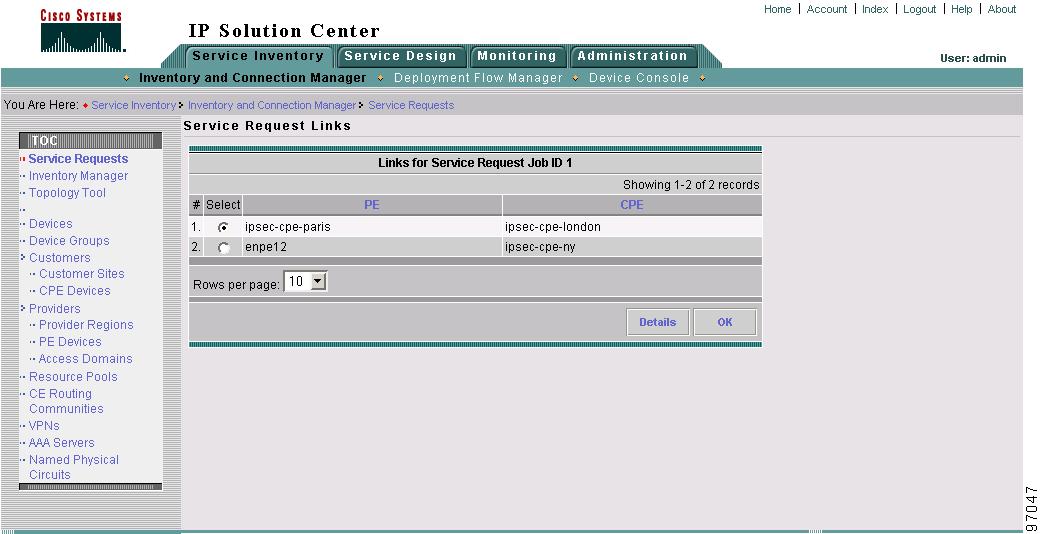
Figure 8-8 shows the Service Request Links window.

Figure 8-8 QoS Service Request Links

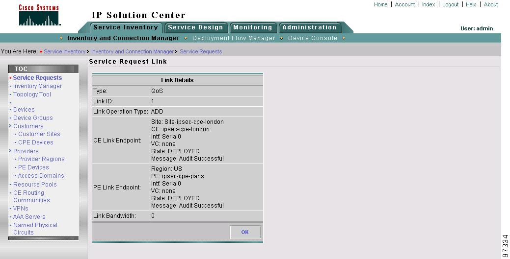
Click Details to display the devices marked with link QoS settings for this service request (Figure 8-9).

Figure 8-9 Service Request Link Details

Click OK (twice) to return to the Service Request Details page.

History

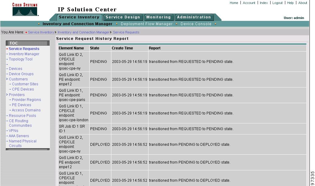
Figure 8-10 shows the Service Request History Report window.

Figure 8-10 Service Request History Report

The history report shows the following information about the service request:

Element name—The device, interface, and subinterfaces participating in this service request.

State—The transition states the element has gone through.

Create Time—The time the element was created for this service request.

Report—The action taken by ISC for the element in this service request.

Configlets

To view QoS configlets:
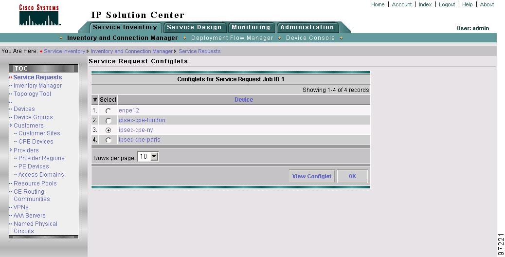

Step 1 Click Configlets on the Service Request Details window. The Service Request Configlets window appears (Figure 8-11).

Figure 8-11 Service Request Configlets

This window shows all devices whose configuration is affected by the service request.

Step 2 Select the device to view the configlet.

Step 3 Click View Configlet. The Configlet for Device window appears (Figure 8-12).

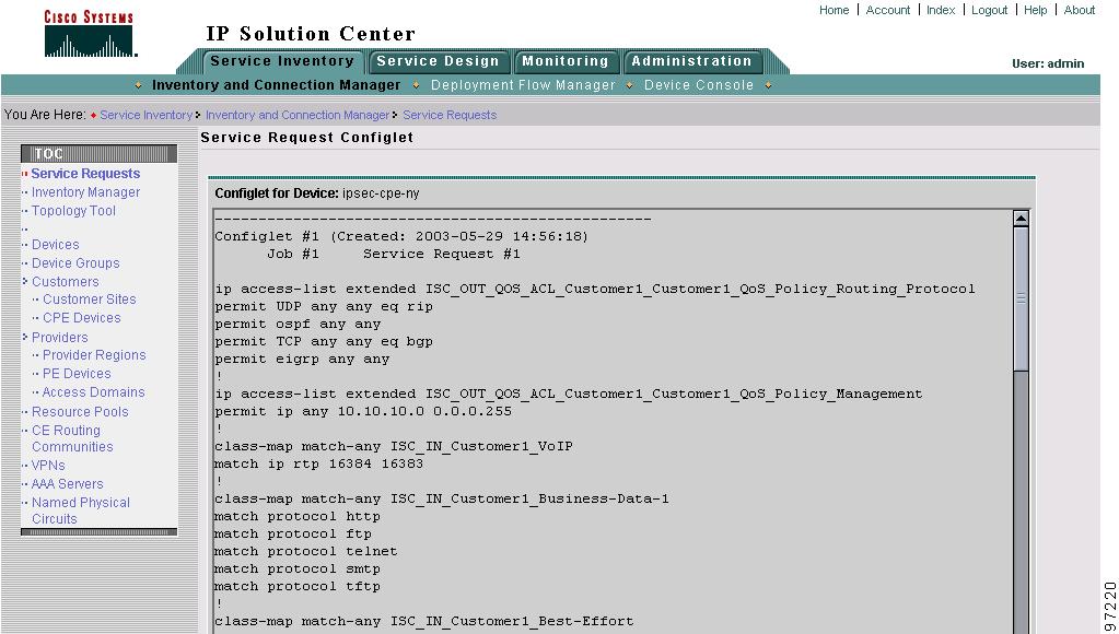
Figure 8-12 QoS Configlet Example

The device configlet shows all commands downloaded to the device configuration during the service request deployment operation.


Note For Ethernet QoS, class-maps corresponding to the Traffic Classifications All IP Traffic and All Mac Traffic are generated only once for a device and not each time a service request is deployed to that device. As a result, these class-maps will not be removed from the device when you decommission a service request.


Step 4 Click OK to exit.


QoS Task Logs

Use the task logs to help you troubleshoot why a service request has failed or to find more details about a service request. This section describes how to view the task logs generated for configuration messages.

To access the task logs:


Step 1 From the Monitoring tab, click Task Manager.

Step 2 Click Logs under the TOC heading.

Step 3 Select the task to view the logs for and click Instances.

Step 4 Select the log to view and click Log. The Task Log window appears.

Step 5 Select the log level from the drop-down menu and click Filter. The log levels are All, Severe, Warning, Info, Config, Fine, Finer, Finest.

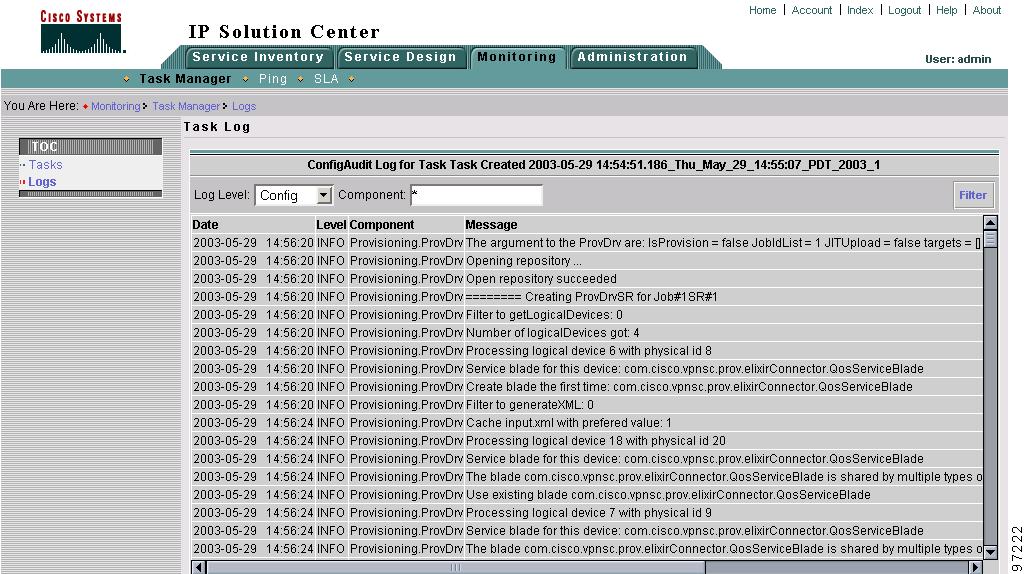
Figure 8-13 shows an example of the information contained in an ISC task log.

Figure 8-13 Task Log Example

Step 6 For example, this window shows all log entries related to the device configuration.

Step 7 To exit from task logs, you must click Task Manager above the TOC for this window.