Feedback
Table Of Contents
Service Level IP QoS Parameters
VoIP, Routing Protocol, and Management Service Classes
Editing the Routing Protocol Service Class
Editing the Management Service Class
Business-Data-1 and Best Effort Service Classes
Editing the Data Service Classes
Parent-level Class-Based Traffic Shaper
Interface-Based Aggregated Rate Limiters
IP QoS Policy Parameters
This chapter describes the parameters, both required and optional, for IP QoS provisioning using the Cisco IP Solution Center (ISC) user interface.
This chapter contains the following sections and subsections:
•
Service Level IP QoS Parameters
–
–
–
Note
Service Level IP QoS Parameters
Service level IP QoS parameters see the entry fields on the service class windows and dialog boxes. These parameters include all entry fields in the VoIP, Management, Routing Protocol, Business-Data-1 and Best Effort service classes, and the traffic classification options for data service classes.
You must enter the bandwidth parameter for all service classes. Typically, a value of one percent is sufficient for Routing Protocol traffic. However, it is common for customers or providers to combine the Management and Routing Protocol into one service class policy. In this case, a larger percentage of bandwidth might be required.
Any class of service can be a class-default class of service. You can simply name the class of service as class-default and ISC will generate the same. Bandwidth is not mandatory for this class of service. Traffic classification is assumed to be rest of traffic.
Note
VoIP, Routing Protocol, and Management Service Classes
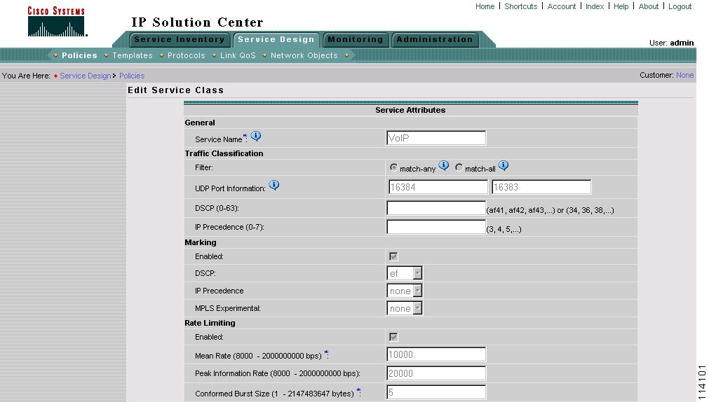
Each service class has a different set of entry fields. The VoIP, Routing Protocol, and Management service classes require similar parameters, and are combined in this section. Figure 6-1 and Figure 6-2 display these service classes.
For Business-Data-1 and Best Effort service class entry fields, see Business-Data-1 and Best Effort Service Classes. The window you see depends on the service class being edited.
Figure 6-1 Edit VoIP Service Class
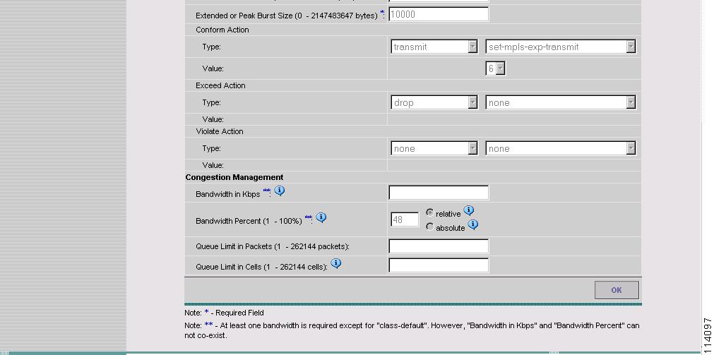
Figure 6-2 Edit VoIP Service Class (Continued)
Table 6-1 describes the entry fields for the VoIP, Routing Protocol, and Management service classes.
Table 6-1 Edit Service Class Entry Fields (VoIP, Routing Protocol, and Management)
Service Name
The name of the service class (VoIP, Routing Protocol, Management, or the name of your choice).
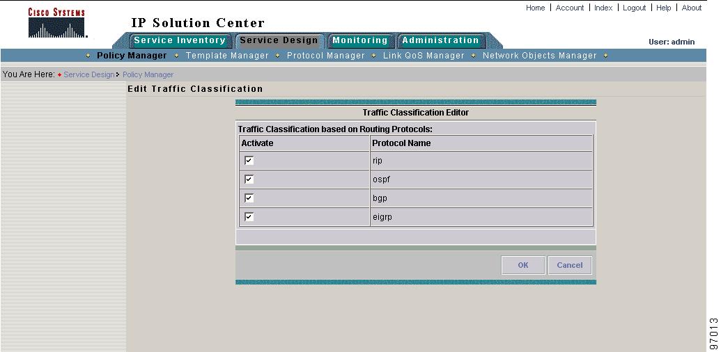
Traffic Classification (Routing Protocol service class only)
Traffic classification based on routing protocol.
Choose from the list of routing protocols. Click Edit to activate one or more of the following routing protocols: RIP, BGP, OSPF, EIGRP. These options are further described in Editing the Routing Protocol Service Class.
Filters:
match-any: Traffic classification passes when any one of the following classifications is met.
match-all: Traffic classification passes when all of the below classifications are met. This is restrictive; for example, combination of UDP Port and DSCP makes sense but not UDP Port and DSCP and IP_Precedence because an IP packet cannot have DSCP and IP_Precedence values at the same time.
UDP Port Information (VoIP service class only)
On routers supporting MQC these two fields see "lower bound UDP port" and "upper bound UDP port". On non-MQC routers, the two fields see port range.
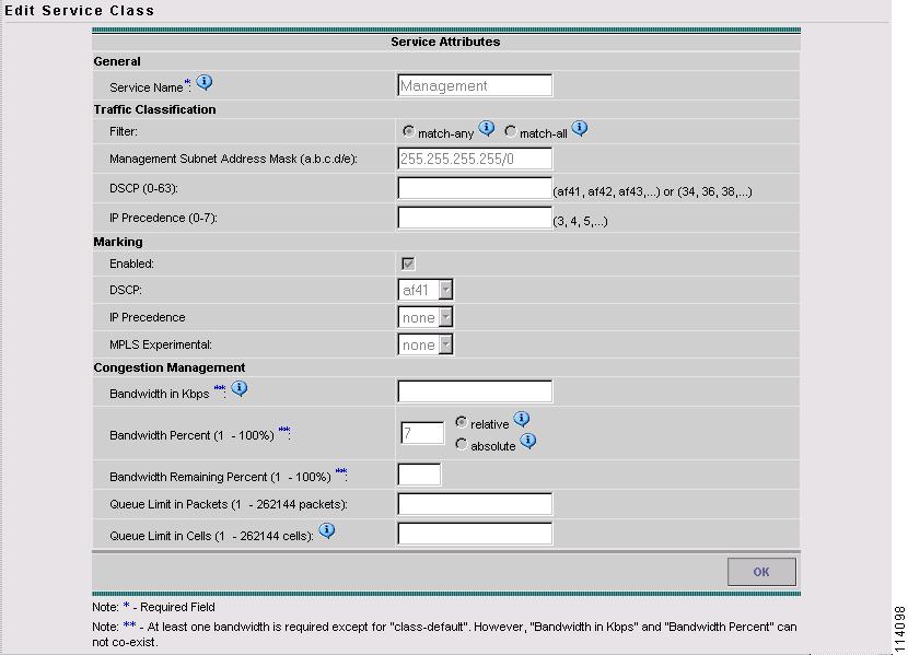
DSCP (VoIP and Management service classes only)
Traffic classification based on the packet's DSCP marking.
IP Precedence (VoIP and Management service classes only)
Traffic classification based on the packet's IP Precedence marking.
Management LAN Address (Management service class only)
Traffic classification based on management LAN address.
To change the default setting for this entry field, see Editing the Properties File.
Enabled
Enable packet marking.
DSCP
Mark packets with a DSCP value.
Note
IP Precedence
Mark packets with an IP Precedence value.
MPLS Experimental
Mark packets with an MPLS Experimental value. This field only appears if you select the Mark MPLS Exp. check box under At Provider Ingress: on the first window of the policy creation.
Enabled
Enable rate-limiting
Mean Rate
The long-term average transmission rate.
Peak Information Rate
Allows support for sustained excess rate.
Conformed Burst Size
How large traffic bursts can be before some traffic exceeds the rate limit.
Note
Extended or Peak Burst Size
How large traffic bursts can be before all traffic exceeds the rate limit. Traffic that falls between the conformed burst size and the extended burst size exceeds the rate limit with a probability that increases as the burst size increases. Configure extended burst by setting the extended burst value greater than the conformed burst value.
Conform Action-Type
The action to take on packets that conform to the specified rate limit.
Single Action
•
•
•
•
Note
Dual Action
•
•
•
Note
Conform Action-Value
The DSCP or IP Precedence or MPLS Exp value for the Conform Action-Type.
Exceed Action-Type
The action to take on packets that conform to the specified rate limit.
Single Action
•
•
•
•
Note
Dual Action
•
•
•
Note
Exceed Action-Value
The DSCP or IP Precedence or MPLS Exp value for the Exceed Action-Type.
Violate Action-Type
The action to take on packets that conform to the specified rate limit.
Single Action
•
•
•
•
Note
Dual Action
•
•
•
Note
Violate Action-Value
The DSCP or IP Precedence or MPLS Exp value for the Violate Action-Type.
Routing Protocol and Management CoS can be configured with Bandwidth Remaining.
Bandwidth in kbps
The bandwidth in kbps (absolute bandwidth) for this service class. This field translates to Priority x and Bandwidth x commands where x is in kbps.
Bandwidth Percent
Percentage of bandwidth to dedicate to congestion management parameters. The range is 1-100 percent. Bandwidth is relative or absolute.
•
•
Queue Limit in Packets
Limit the queue depth of the congesting traffic. The range is 1 to 262144 packets.
Queue Limit in Cells
Limit the queue depth of the congesting traffic. The range is 1 to 262144 cells.
Note
Editing the Routing Protocol Service Class
The Routing Protocol service class provides you with a method of classifying traffic based on the routing protocols. This is the default method for traffic classification in ISC.
Use the Edit Traffic Classification window to change the list of protocols to use for the Routing Protocol service class (Figure 6-3).
Figure 6-3 Edit Traffic Classification
Select the routing protocols to use and click OK.
Editing the Management Service Class
This section describes how to edit the Management service class.
Figure 6-4 shows the Edit Service Class window for the Management service class.
Figure 6-4 Edit Management Service Class
Use this window to specify QoS parameters for the Management service class. The following are required fields:
•
•
•
•
•
Note
To add another Management service class, use the Add Data CoS button on the Edit QoS Policy window. See Adding a Data Service Class for more information.
Business-Data-1 and Best Effort Service Classes
For the two data service classes, Business-Data-1 and Best Effort, the parameters are nearly identical. The entry field descriptions are combined in this section. The only difference between the two data service classes is the Traffic Classification parameter:
•
•
For VoIP, Routing Protocol, and Management service class entry fields, see VoIP, Routing Protocol, and Management Service Classes.
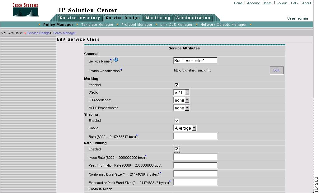
Figure 6-5 and Figure 6-6 show the general information, marking, and shaping fields for the Business-Data-1 service class.
Figure 6-5 Business-Data-1
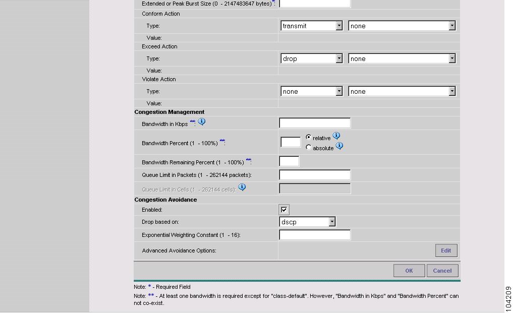
Figure 6-6 Business-Data-1 (continued)
Table 6-2 describes the entry fields for the data service classes. The entry fields you see depend on which service class is being edited.
Table 6-2 Edit Service Class Entry Fields (Business Data-1 and Best Effort)
Service Class
The name of the service class (Business-Data-1, Best Effort, or the name of your choice).
Traffic Classification
Traffic classification based on protocols.
Choose from the list of protocols, or add another protocol. Click Edit to activate one or more of the following protocols: HTTP, FTP, Telnet, SMTP, TFTP.
These options are further described in Traffic Classification.
Enabled
Enable packet marking.
DSCP
Mark packets with a DSCP value.
Note
IP Precedence
Mark packets with an IP Precedence value.
MPLS Experimental
Mark packets with an MPLS Experimental value. This field only appears if you select the Mark MPLS Exp. check box under At Provider Ingress: on the first window of the policy creation.
Enabled
Enable class-based traffic shaping parameters.
To specify interface-based traffic shaping parameters, see Aggregated Traffic Shapers.
Shape
Specify average or peak rate shaping.
•
•
Note
Rate
Committed information rate.
Enabled
Enable rate-limiting
Mean Rate
The long-term average transmission rate.
Peak Information Rate
Allows support for sustained excess rate.
Conformed Burst Size
How large traffic bursts can be before some traffic exceeds the rate limit.
Note
Extended or Peak Burst Size
How large traffic bursts can be before all traffic exceeds the rate limit. Traffic that falls between the conformed burst size and the extended burst size exceeds the rate limit with a probability that increases as the burst size increases. Configure extended burst by setting the extended burst value greater than the conformed burst value.
Conform Action-Type
The action to take on packets that conform to the specified rate limit.
Single Action
•
•
•
•
Note
Dual Action
•
•
•
Note
Conform Action-Value
The DSCP or IP Precedence or MPLS Exp value for the Conform Action-Type.
Exceed Action-Type
The action to take on packets that conform to the specified rate limit.
Single Action
•
•
•
•
Note
Dual Action
•
•
•
Note
Exceed Action-Value
The DSCP or IP Precedence or MPLS Exp value for the Exceed Action-Type.
Violate Action-Type
The action to take on packets that conform to the specified rate limit.
Single Action
•
•
•
•
Note
Dual Action
•
•
•
Note
Violate Action-Value
The DSCP or IP Precedence or MPLS Exp value for the Violate Action-Type.
Routing Protocol and Management CoS can be configured with Bandwidth Remaining.
Bandwidth in kbps
The bandwidth in kbps (absolute bandwidth) for this service class. This field translates to Bandwidth x commands where x is in kbps.
Bandwidth Percent
Percentage of bandwidth to dedicate to congestion management parameters. The range is 1-100 percent. Bandwidth is relative or absolute.
•
•
Bandwidth Remaining Percent
The range is 1-100 percent.
Queue Limit in Packets
Limit the queue depth of the congesting traffic. The range is 1- 262144 packets.
Queue Limit in Cells
Limit the queue depth of the congesting traffic. The range is 1- 262144 cells.
Enabled
Enable congestion avoidance.
Drop based on
Drops packets based on the IP Precedence or DSCP value.
Exponential Weighing Constant
The value used in the average queue size (weighted random early detection, or WRED) calculation. This value is used to determine the queue reserved for this service class.
Advanced Avoidance Options
Click Edit to add Advanced Avoidance Options. See Advanced Avoidance Options.
Editing the Data Service Classes
This section describes how to change the traffic classification parameters for the data service classes and how to add advanced options for congestion avoidance.
Traffic Classification
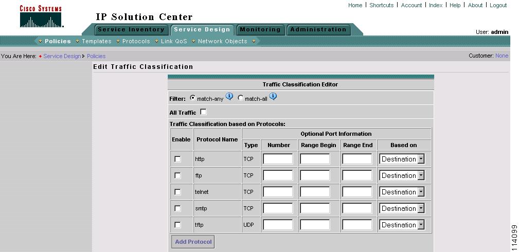
Use the Traffic Classification window to set or change the traffic classification parameters. Figure 6-7 and Figure 6-8 show the traffic classification settings for this service class. It includes some protocols that are enabled by default.
Figure 6-7 Traffic Classification Editor—Data Service Class
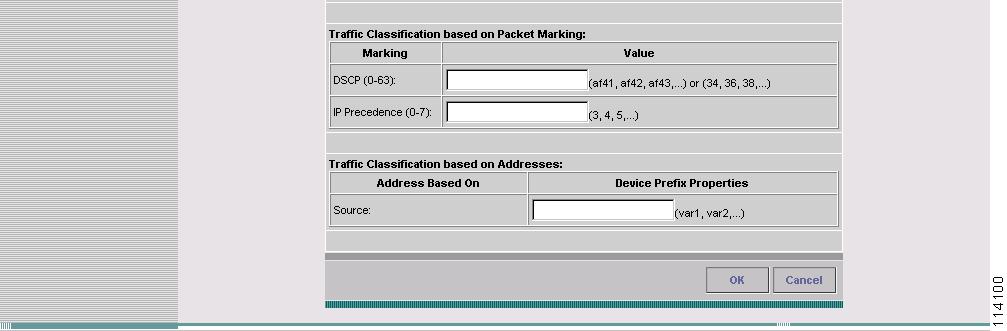
Figure 6-8 Traffic Classification Editor—Data Service Class (continued)
The entry fields are described in Table 6-3.
Table 6-3 Traffic Classification Editor Entry Fields
match-any: Traffic classification passes when any one of the following classifications is met.
match-all: Traffic Classification passes when all of the conditions below are met. This is restrictive; for example, a combination of any one protocol and DSCP makes sense but not more than one protocol and DSCP and IP_PRECEDENCE since an IP packet cannot belong to more than one Protocol and cannot have DSCP and IP_PRECEDENCE values at the same time.
Selects traffic classification based on all protocols.
Enable
Enables traffic classification for this protocol.
Port Type
TCP or UDP port (optional).
Port Number
The TCP or UDP port number to use for this protocol. (optional)
Port Range Begin
Specifies the beginning port number in a range of ports. (optional)
Port Range End
Specifies the end port number in a range of ports. (optional)
Based On
Traffic classification is based on the source or destination port for this protocol. (optional)
Add Protocol
Add another protocol to use for traffic classification.
NBAR
NBAR (Network Based Application Recognition)
On platforms running IOS that support NBAR based traffic classification, you can provide NBAR support such as:
•
where protocol name is citrix, cuseeme, for example.
•
To make use of this feature, enter the protocol or url name in the protocol name field. Do not edit the remaining fields for the protocol.
Extended ACL
Extended ACL (Access Control List)
To create named ACLs such as:
•
•
where port_type is UDP or TCP. Port information can be source-based or destination-based.
To make use of this feature, leave the protocol name field blank.
DSCP (0-63):
Selects traffic classification based on DSCP value.
IP Precedence (0-7):
Selects traffic classification based on IP Precedence value.
Source
Selects traffic classification based on source IP addresses. This is accomplished using variables defined using the Network Objects Manager. For more information, see the Traffic Classification Based on Variables.
Advanced Avoidance Options
This section describes the advanced congestion avoidance parameters for the data service classes.
To add advanced congestion avoidance options:
Step 1
Step 2
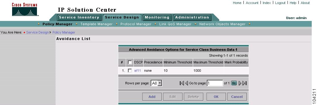
Figure 6-9 Avoidance List
This window lists any available congestion avoidance options that have been configured, including the DSCP or IP Precedence value, the minimum and maximum threshold, and the mark probability.
From this window you can also Add, Edit, or Delete any congestion avoidance option.
Step 3
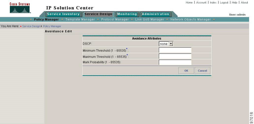
Figure 6-10 Avoidance Edit
Step 4
•
•
–
–
–
–
•
Step 5
Adding a Data Service Class
If your QoS policy requires additional service classes, use the data service class template provided with ISC to add another management or data service class.
To add another service class, click Add Data CoS from the Edit QoS Policy window. Enter a name and the service class attributes. See Table 6-2 for a description of each field.
Deleting a Service Class
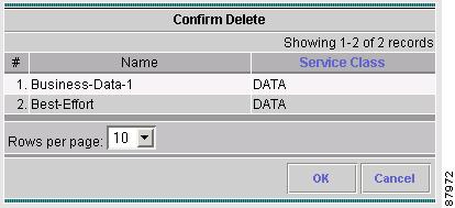
To delete an unwanted service class from your QoS policy, select the service class on the Edit QoS Policy window. Click Delete, confirm (Figure 6-11), and click OK.
Figure 6-11 Delete Service Class
Link Level QoS Parameters
Link level QoS parameters see QoS settings that are based on the CPE-PE link (called IP link QoS settings). These interface-based parameters include aggregated traffic shaping, link efficiency settings, and interface-based rate limiting.
This section describes the link level QoS parameters for IP link QoS settings. Link level QoS parameters include all entry fields for the link QoS settings.
Aggregated Traffic Shapers
Aggregated traffic shaping allows you to control the traffic leaving an interface. In ISC, you can select an aggregated traffic shaper for each IP link.
To apply class-based traffic shaping parameters, see the Editing the Data Service Classes.
Aggregated traffic shapers are optional. ISC supports the following aggregated traffic shapers:
•
•
•
•
•
•
•
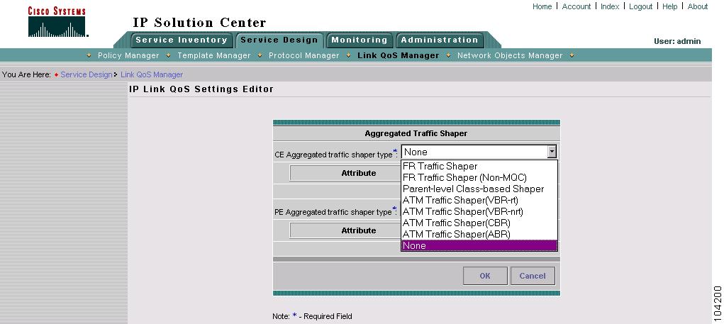
You set aggregated traffic shaping parameters from the IP Link QoS Settings Editor window (Figure 6-12).
Figure 6-12 Select Aggregated Traffic Shaper Type
Select one aggregated traffic shaper for the CE and one for the PE. Table 6-4 describes the aggregated traffic shaper types.
The following sections describe the windows and entry fields for the aggregated shaper types. You see a different dialog box depending on which of the following you choose.
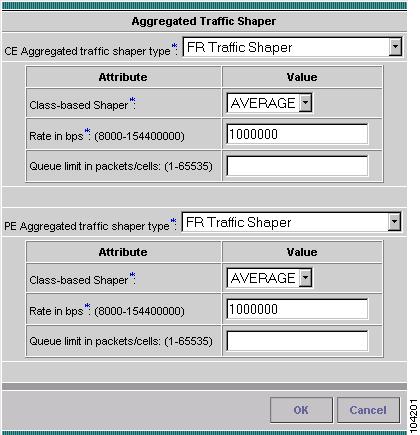
FR Traffic Shaper
The FR Traffic Shaper (Figure 6-13) is a version of a class-based parent level shaper that operates only in distributed mode on versatile interface processor-based routers, such as the Cisco 7500 series platforms.
Figure 6-13 FR Traffic Shaper
The entry fields are described in Table 6-5.
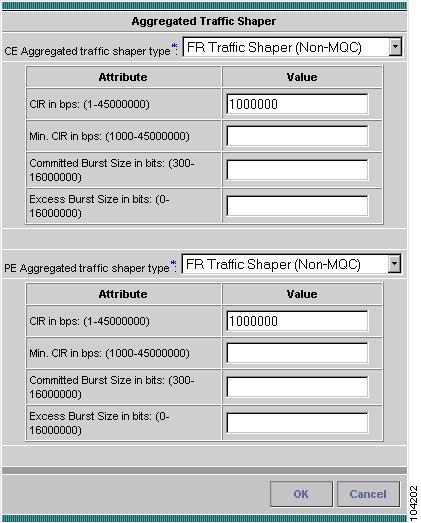
FR Traffic Shaper (Non-MQC)
The Non-MQC Frame Relay traffic shaper (FRTS) uses queues on a Frame Relay network to limit surges that can cause congestion. Data is buffered and then sent into the network in regulated amounts to ensure that the traffic will fit within the promised traffic envelope for the particular connection.
Use FRTS Non-MQC (Figure 6-14) on all ISC-supported low-end router platforms (Cisco 7200 series and below).
Figure 6-14 FRTS Non-MQC
The entry fields are described in Table 6-6.
Note
Parent-level Class-Based Traffic Shaper
Parent-level class-based traffic shapers are used for nested policies where a bottom-level policy identifies one or more classes of traffic, and a top-level policy shapes the output of the traffic classes into a single shape rate. You can apply nested policies to interfaces or subinterfaces.
The parent-level class-based shaper dialog box and entry fields are the same as the FR Traffic Shaper. See FR Traffic Shaper.
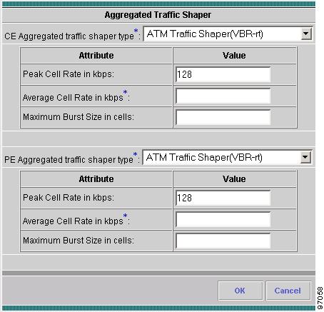
ATM Traffic Shaper (VBR-rt)
VBR-rt is intended for real-time applications, (for example, those requiring tightly constrained delay and delay variation, like voice and video applications). VBR-rt connections are characterized in terms of a peak cell Rate (PCR), sustainable cell rate (SCR), and maximum burst size (MBS). See Figure 6-15.
Figure 6-15 ATM Traffic Shaper VBR-rt
The entry fields are described in Table 6-7.
Tip
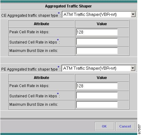
ATM Traffic Shaper (VBR-nrt)
This section describes ATM traffic shaping using variable bit rate non real-time.
VBR-nrt implementations follow a leaky bucket or token bucket algorithm. An ATM VC requires a token in the bucket to transmit a cell. The algorithm replenishes tokens in the bucket at the rate of the sustained cell rate (SCR). If a source is idle and does not transmit for a period of time, tokens accumulate in the bucket. An ATM VC can use the accumulated tokens to burst at the rate of peak cell rate (PCR) until the bucket is empty, at which point tokens are replenished at the rate of SCR. See Figure 6-16.
Figure 6-16 ATM Traffic Shaper VBR-nrt
The entry fields are described in Table 6-8.
Tip
The values for this dialog box can be calculated using the following formulas:
•
•
•
Tip
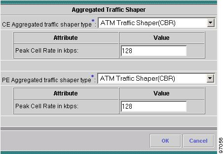
ATM Traffic Shaper (CBR)
The CBR traffic shaper is used by connections that require static amount of bandwidth that is continuously available during the connection lifetime. This amount of bandwidth is characterized by a Peak Cell Rate (PCR) value. Use CBR traffic shapers for real-time traffic. See Figure 6-17.
Figure 6-17 ATM Traffic Shaper CBR
The Peak Cell Rate is the maximum rate at which you expect to transmit data, voice and video.
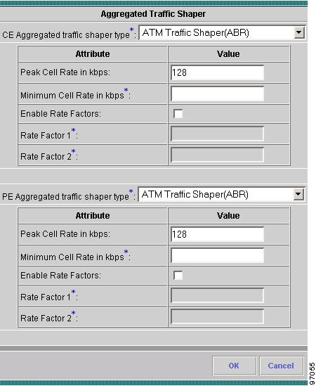
ATM Traffic Shaper (ABR)
ABR traffic shaping configures a router to transmit at a rate that varies with the amount of bandwidth available in the network or along the end-to-end transmission path. When the network is congested and other source devices are transmitting, there is little available or leftover bandwidth. However, when the network is not congested, bandwidth is available for use by other active devices. ABR allows end-system devices like routers to take advantage of this extra bandwidth and increase their transmission rates. See Figure 6-18.
Figure 6-18 ATM Traffic Shaper ABR
The entry fields are described in Table 6-9.
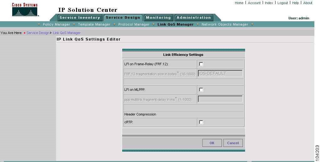
Link Efficiency Settings
Link efficiency settings are based on the CPE-PE link itself and are used to minimize serialization delay on the link. ISC uses methods of fragmentation and compression to minimize this delay.
ISC supports the following link efficiency settings:
•
•
•
Figure 6-19 shows the IP Link QoS Settings Editor window.
Figure 6-19 Link Efficiency Settings
Table 6-10 describes the entry fields for the Link Efficiency Settings window.
Tip
Interface-Based Aggregated Rate Limiters
Interface-based aggregated rate limiters allow you to control the maximum rate of traffic sent or received on an interface for the CPE-PE link. You can also specify traffic handling policies for when the traffic conforms or exceeds the specified rate limit.
Aggregate rate limits match all packets or a specified subset of packets on an interface or subinterface. To specify class-based rate limiting parameters, see the Creating the Service Level IP QoS Policy.
ISC supports the following interface-based rate limiter parameters:
•
•
•
•
•
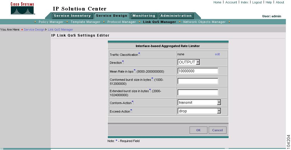
Figure 6-20 shows the Interface-based Aggregated Rate Limiter window.
Figure 6-20 Interface Based Aggregated Limiter
Table 6-11 describes the entry fields for the Interface-based Aggregated Rate Limiter window. All fields in this window are required.
Table 6-11 Interface-based Aggregated Rate Limiter Entry Fields
Traffic Classification
Specifies the method for classifying traffic. Click Edit to access the Traffic Classification Editor. For more information, see Traffic Classification.
Direction
The direction of traffic to apply rate limiting parameters to. Choose from Input or Output.
Mean rate in bps
The range is 8000 to 2000000000 bps.
Conformed burst size in bytes
The range is 1000 to 512000000 bytes.
Note
Extended burst size in bytes
The range is 2000 to 1024000000 bytes.
Conform-Action
Specifies how to handle packets that conform to the configured rate limit.
•
•
Note
•
•
•
•
•
•
Exceed-Action
Specifies how to handle packets that exceed the configured rate limit. The options are the same as Conform-Action.