Feedback
Table Of Contents
Service Provider Network Architecture
IP QoS Provisioning Strategies
Ethernet QoS Provisioning Strategies
Network Architecture
A service provider network architecture contains access routers, distributed routers and core routers or ATM switches. Access routers terminate customer connections at the edge of the network.
IP QoS provisioning with the Cisco IP Solution Center (ISC) is configured on the access circuit that involves the access router (provider edge devices, or PEs) in the service provider network and the customer premise equipment (CPEs) in the customer network.
Ethernet QoS provisioning with ISC supports a subset of the features required for the Metro Ethernet 2.1 Solution (Upper Kensington). With Ethernet QoS, ISC can deploy QoS Policies on Cisco Catalyst switches in a provider's network.
This chapter includes the following sections:
•
Service Provider Network Architecture
•
•
Service Provider Network Architecture
The service provider network architecture, supported within the scope of the IP QoS provisioning model in ISC is:
•
•
•
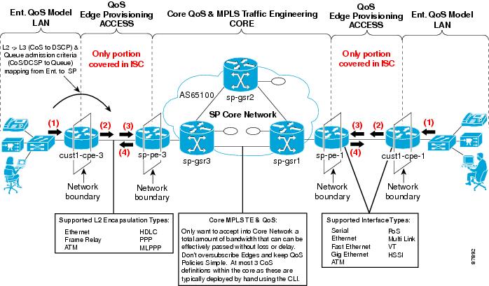
These QoS components and concepts are represented in Figure 2-1.
Figure 2-1 QoS Components and Concepts
IP QoS Service Model
The IP QoS service model in ISC is designed so that QoS provisioning is implemented for traffic that enters the access circuit at the network edge (CPE), and through the distribution portion (the CPE-PE link).
This type of IP QoS provisioning involves traffic through several different types of devices, link speeds, and encapsulation types. For this reason, an ISC QoS policy is divided into two categories:
•
Typically, a service provider creates 3 or 4 service classes for each QoS policy. For example, a service provider might have a Platinum, Gold, Silver, and Bronze QoS policies, and each of these policies might contain 3 service classes; a VoIP, a management, and a data service class (Best-Effort or Business-Data-1).
•
Typically, a service provider creates several link level QoS settings. For example, a service provider might create a link QoS setting for different bandwidths and encapsulation types, such as; FR_64K_gold, FR_64K_silver, FR_128K_bronze, ATM_1MBPS_gold, and Ethernet_2mbps_Silver.
ISC provides two levels of QoS policies because a QoS service request might contain one or more links with different circuit bandwidths and encapsulation types. The service level policy is designed for a type of service, like voice, but can apply to more than one link type. The link level policy is designed for different link speeds, like 1 Mbps, and can apply QoS provisioning per link.
To provision QoS parameters for devices in a service request, a network operator must:
•
•
For example, if the QoS service request is comprised of two links; a Frame-Relay link with a bandwidth of 64kbps, and an ATM link, with a bandwidth of 1 mbps, and the service level agreement (SLA) purchased by the enterprise customer is the Gold policy, the following settings might be associated with the QoS service request:
–
–
–
QoS policies can either be customer-oriented or provider-oriented. Typically, service provider networks have a combination of both service level and link level QoS policies.
For more information on the QoS service model, see "QoS Service Model Overview."
IP QoS Provisioning Strategies
ISC configures IP QoS at the access circuit, which involves the PE devices in the service provider network and the CPE devices in the customer network. A QoS policy is applied to the selected set of access circuits using a QoS service request.
Typically, the points of congestion in the access circuit are:
•
•
This section describes a QoS provisioning strategy: where the congestion points in the network might be, where to apply QoS parameters, and which QoS provisioning components to use.
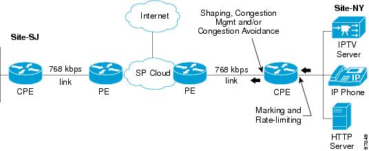
Managed CPE Scenario
A managed CPE scenario occurs when the CPE is owned and managed by the service provider. In this network scenario, you can either apply QoS provisioning for the CPE only or for both the CPE and PE.
This section describes QoS provisioning strategies for both CPE only and CPE-PE scenarios.
Managed CPE Only
Figure 2-2 illustrates a network where QoS provisioning is configured only for the managed CPE device.
Figure 2-2 Managed CPE Scenario
In this QoS provisioning scenario:
•
•
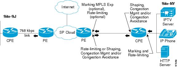
Managed CPE and PE
Figure 2-3 illustrates a network where QoS provisioning is configured for both the managed CPE and the PE device.
Figure 2-3 Managed CPE and PE Scenario
In this QoS provisioning scenario:
•
•
•
Unmanaged CPE Scenario
An unmanaged CPE scenario occurs when the CPE is not owned by the service provider, but ISC is aware of the device configuration and interface information. This information must be provided by the owner of the CPE device.
In this QoS provisioning scenario:
•
See Cisco IP Solution Center Infrastructure Reference, 4.0 for more information on manually creating CPE devices.
•
See Creating the Service Level IP QoS Policy for more information.
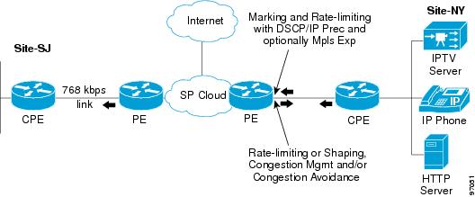
PE Only Scenario
For a PE only scenario, the service provider's enterprise customer is responsible for applying the QoS configuration at the CPE interfaces.
Figure 2-4 PE Only Scenario
In this QoS provisioning scenario:
•
•
See "Provisioning Process for IP QoS," for more information on the QoS provisioning process.
Ethernet QoS Service Model
The Ethernet QoS service model in ISC is designed so that QoS provisioning is implemented for traffic that enters the access circuit at the network edge (CPE), and through the distribution portion (the CPE-PE link).
Ethernet QoS policies correspond to Ethernet QoS service classes. QoS service classes provide a method for classifying traffic.
A typical service provider network might create different QoS policies, and each QoS policy might contain 3 to 4 service classes. For example, a service provider might have gold, silver, and bronze QoS policies, each specifying different service level agreements (SLA), and each of those QoS policies might contain one or more service classes. Most networks require at least a voice and a data service class.
To provision Ethernet QoS parameters for devices in a service request, a network operator must:
•
•
•
•
•
•
•
Ethernet QoS policies can either be customer-owned or provider-owned.
For more information on the Ethernet QoS service model, see "Applying QoS Policies to VPN Services".
Ethernet QoS Provisioning Strategies
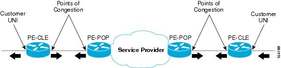
Each Ethernet link in a service request (L2VPN, MPLS, or VPLS) might contain one or two attachment circuits (end-to-end link). Each attachment circuit corresponds to one point-to-cloud QoS Link. A link contains one or two end-points: PE-CLE and PE-POP
An Ethernet QoS service request binds one or more QoS links to a QoS policy. A QoS template can be attached to each end-point in a QoS link.
In a service-provider managed Ethernet QoS environment, the following three points in the access circuit are regarded as potential points of congestion:
•
•
•
Figure 2-5 shows the Ethernet QoS points of congestion.
Figure 2-5 Ethernet QoS Points of Congestion