Feedback
Table Of Contents
Applying QoS Policies to VPN Services
Service Level Ethernet QoS Policy
Service Level Ethernet QoS Policy Entry Fields
Ethernet QoS for L2VPN, VPLS, and Layer 2 Access into MPLS VPN
Creating a QoS Service Request from an L2VPN, MPLS, or VPLS Service Request
Creating a QoS Service Request from an MPLS Service Request
Applying QoS Policies to VPN Services
The Cisco IP Solution Center (ISC) supports Ethernet QoS provisioning at the access circuit (the CPE-PE link). ISC can provision QoS policies for a network independent of VPN services (IP QoS) or in addition to VPN services that have been provisioned by ISC (Ethernet QoS and IP QoS for MPLS VPN).
•
IP QoS provisioning is described in "Provisioning Process for IP QoS."
•
Additionally, ISC supports the following QoS parameters for VPN services:
•
This chapter describes how to apply QoS policies to VPN services provisioned by ISC.
In ISC, the Ethernet QoS service model is comprised of:
•
•
The chapter contains the following sections:
•
•
Service Level Ethernet QoS Policy
The Ethernet QoS policy is the set of rules or conditions that apply to frames as they come across each port. This set of rules is defined in an Ethernet QoS service class.
An Ethernet QoS service class provides a method for classifying traffic flows into classes of service (CoS) so that you can apply the appropriate QoS parameters to a class of traffic instead of applying them to all traffic. For example, all IP traffic might be grouped into a single class so that bandwidth is allocated for the class and not for individual traffic flows.
An Ethernet QoS service class can include:
•
•
•
•
A typical service provider network might create different QoS policies, and each QoS policy might contain 3 to 4 service classes. For example, a service provider might have gold, silver, and bronze QoS policies, each specifying different service level agreements (SLA), and each of those QoS policies might contain one or more service classes. Most networks require at least a voice, and a data service class.
ISC provides four default CoS templates to modify.
•
•
•
•
Select the service classes to use in the Ethernet QoS policy and edit each one with the required parameters. All service classes should contain, at least, rate limiting information. You can also add a service class, delete an unused service class, or change the order of the service classes. ISC supports the number of service classes defined by the Cisco differentiated services (DiffServ) architecture; up to 64 classes for DSCP traffic, and up to 8 service classes for IP Precedence traffic.
The following sections describe how to create the CoS portion of an Ethernet QoS Policy using the ISC user interface. For detailed information on the entry fields for each service class parameter, see Service Level Ethernet QoS Policy Entry Fields.
To create an Ethernet QoS policy:
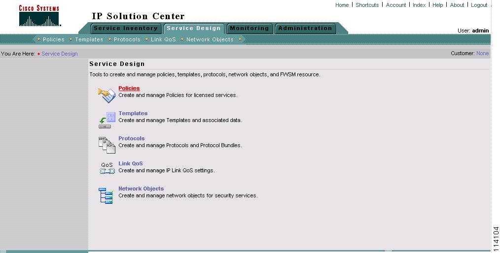
Step 1
Figure 7-1 Policy Manager
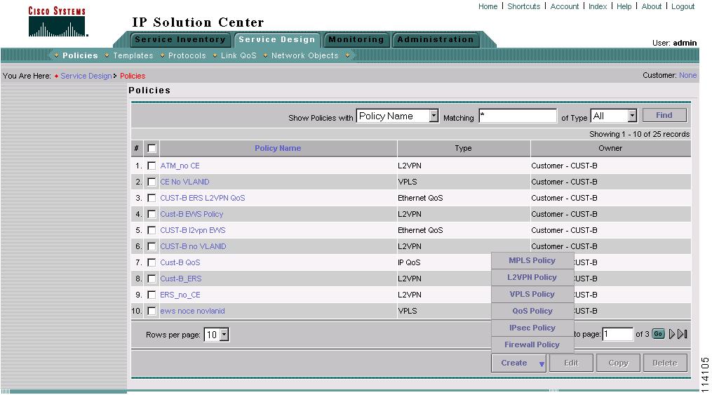
The Policies window appears (Figure 7-2).
Figure 7-2 Create QoS Policy
The Policies window lists all policies that currently exist for the different ISC services. Use this window to create, edit, or delete to an existing policy.
Note
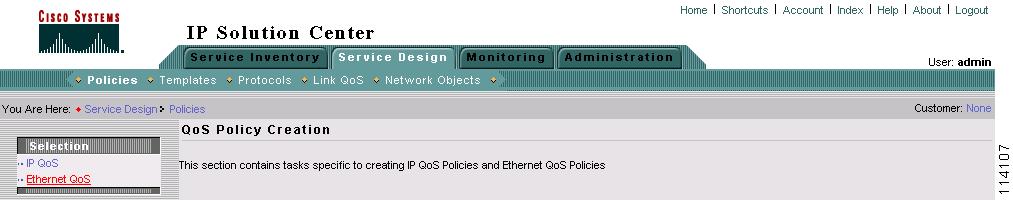
Step 2
Figure 7-3 Create QoS Policy
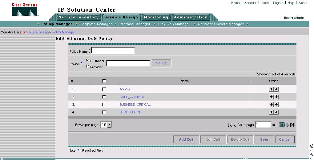
Step 3
Figure 7-4 Edit Ethernet QoS Policy
The Edit Ethernet QoS Policy window lists the policy name, the owner (customer or provider) for this policy, and the four default service classes for ISC. Use this window to select and edit the service classes to use in the QoS policy.
Step 4
Note
Step 5
Step 6
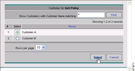
Figure 7-5 Select Customer for QoS Policy
This identifies the customer for the QoS policy. You return to the Edit Ethernet QoS Policy window.
Step 7
Step 8
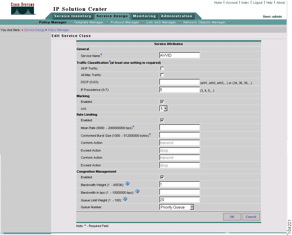
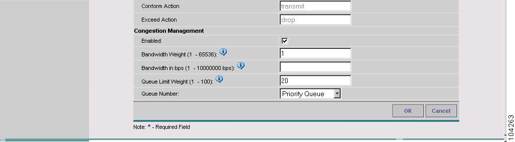
Figure 7-6 Edit Service Class—AVVID
Figure 7-7 Edit Service Class AVVID (continued)
Step 9
Depending on the service class you are editing, you receive the appropriate window. For a detailed explanation of the entry fields for this service class and the windows for the other service classes, see Service Level Ethernet QoS Policy Entry Fields.
Step 10
To change the processing order of the service classes, use the up and down arrow keys on the Edit Ethernet QoS Policy window. The processing order dictates the order in which the class-maps are applied to the policy map and subsequently the order in which they are processed.
Step 11
Step 12
Step 13
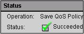
When you save an Ethernet QoS policy, a status information box is displayed on the bottom left of the ISC window. The following examples show the different status messages and user action required, to correct any problems.
a.
Figure 7-8 Save is Successful
b.
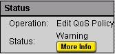
Figure 7-9 Edit QoS Policy with Warning
c.
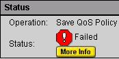
Figure 7-10 Save Unsuccessful
Note
Service Level Ethernet QoS Policy Entry Fields
The service level Ethernet QoS policy contains entry fields on the service class windows and dialog boxes. These include all entry fields in the Architecture for Voice, Video and Integrated Data (AVVID), Call Control, Business Critical, and Best Effort service classes.
All the Ethernet QoS service classes have the same set of entry fields, including newly created service classes.
The window you see depends on the service class being edited. Figure 7-11 and Figure 7-12 show the Edit Service Class window for the AVVID service class.
Figure 7-11 Edit Ethernet QoS Service Class
Figure 7-12 Edit Ethernet QoS Service Class (continued)
Table 7-1 describes the entry fields for the service classes.
Ethernet QoS for L2VPN, VPLS, and Layer 2 Access into MPLS VPN
This section describes how to apply QoS parameters to an existing Ethernet (L2VPN, MPLS, or VPLS) service request.
Note
Checking Prerequisites
Before you can apply QoS parameters to an Ethernet network, you must already have:
•
•
See Cisco IP Solution Center L2VPN User Guide, 4.0 for more information on creating L2VPN and VPLS service requests.
Creating a QoS Service Request from an L2VPN, MPLS, or VPLS Service Request
The steps for creating an Ethernet QoS service request are as follows:
•
•
•
•
•
•
•
Use the following procedure to create a QoS service request from an L2VPN, MPLS, or VPLS Service Request:
Step 1
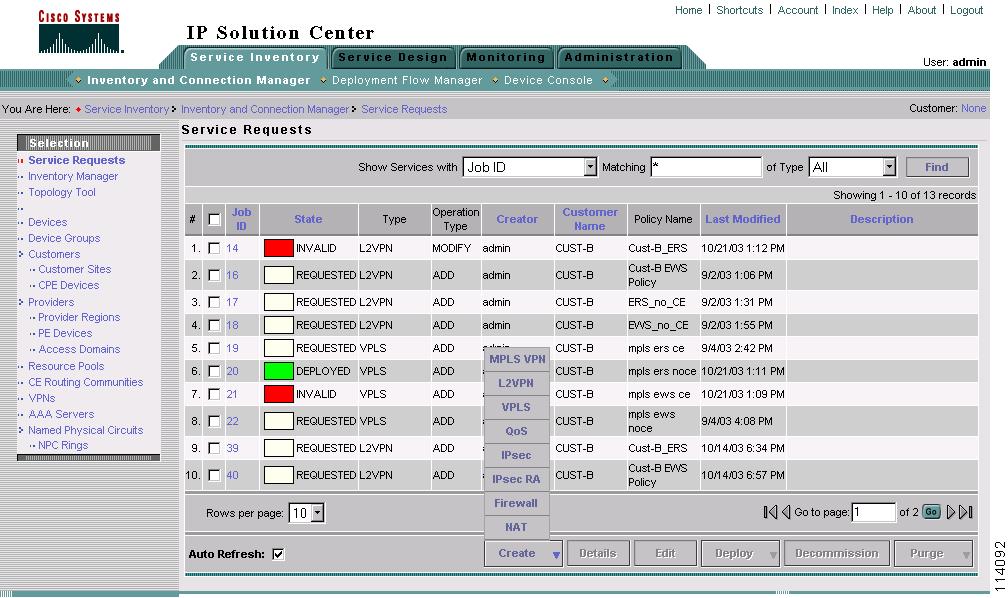
Figure 7-13 Service Requests List
The Service Requests window lists the current list of service requests for this user name.
Note
Step 2
Step 3
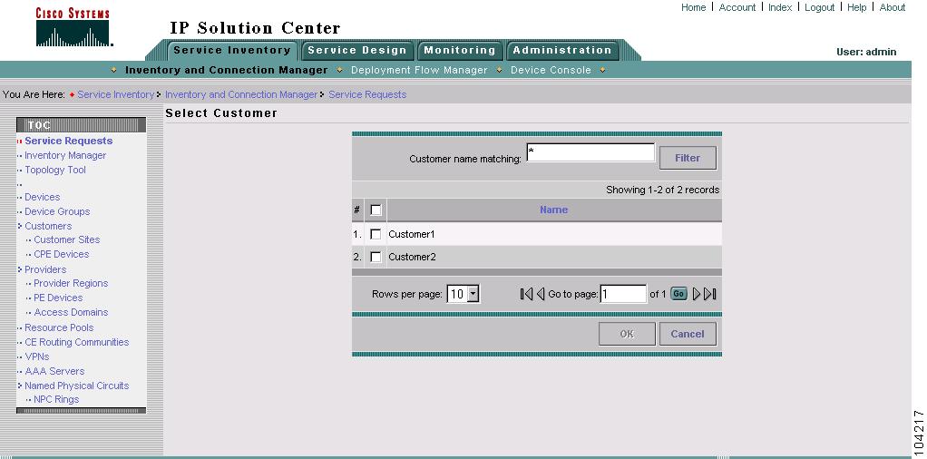
Figure 7-14 Select Customer
The QoS Service Editor window appears (Figure 7-15).
Figure 7-15 QoS Service Editor
Step 4
Figure 7-16 Select L2VPN Service Request for QoS
This window lists existing service requests, including the deployment state, the customer, and policy name.
Step 5
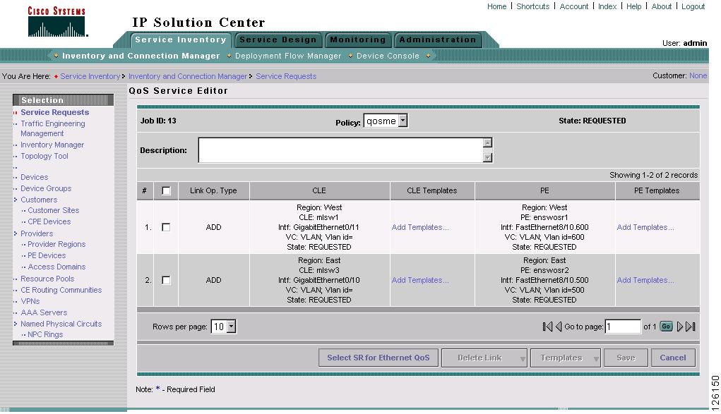
Figure 7-17 QoS Service Editor
This window lists the QoS links and includes the following information about the CLE-PE link:
•
•
•
•
•
Note
For more information on L2VPN and VPLS provisioning, see Cisco IP Solution Center L2VPN User Guide, 4.0. For more information on MPLS VPN provisioning, see Cisco IP Solution Center MPLS VPN User Guide, 4.0.
From this window you can delete links.
Step 6
Step 7
To apply QoS policies to the VPN service request, you must deploy the QoS service request. When you deploy a QoS service request, ISC compares the device information in the repository (the ISC database) with the current device configuration and generates a configlet.
When the configlets are generated and downloaded to the devices, the QoS service request enters the Pending state. When the devices are successfully audited, the QoS service request enters the Deployed state.
IP QoS for MPLS VPNs
ISC supports the following QoS parameters for MPLS VPNs:
•
•
•
The following sections describes how to apply IP QoS parameters to an MPLS service request.
Checking Prerequisites
For an MPLS network, ISC marks packets with MPLS Experimental values (MPLS Exp.) at the PE ingress interface. Before you can apply QoS parameters to an MPLS network, you must already have:
•
•
See Cisco IP Solution Center MPLS VPN User Guide, 4.0 for more information on creating MPLS service requests.
•
Creating a QoS Service Request from an MPLS Service Request
Use the following procedure to create a QoS service request from an MPLS service request:
Step 1
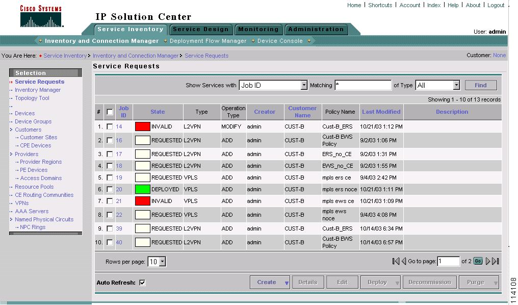
Figure 7-18 Service Requests List
The Service Requests window lists the current list of service requests.
Note
Step 2
Figure 7-19 Create QoS Service Request
The Select Customer window appears as shown in Figure 7-20.
Step 3
Figure 7-20 Select Customer
The QoS Service Editor window appears (Figure 7-21).
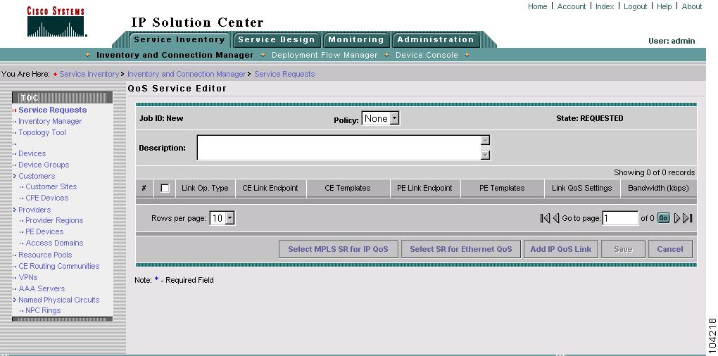
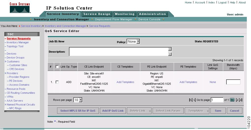
Figure 7-21 QoS Service Editor
The QoS Service Editor window displays the following information about a link:
•
•
•
•
•
•
•
Step 4
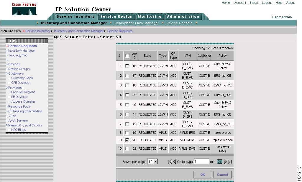
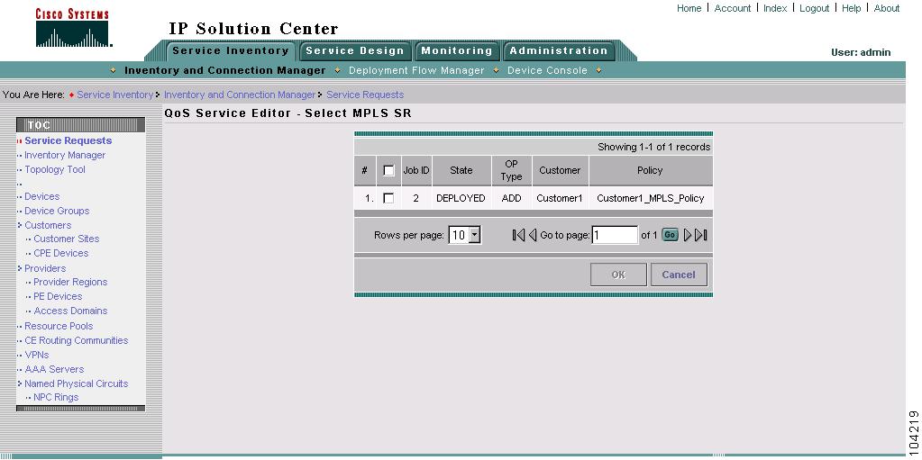
Figure 7-22 Select MPLS Service Request for QoS
This window lists existing MPLS service requests, including the deployment state, the customer, and policy name.
Step 5
Figure 7-23 QoS Service Editor
This window lists the CE and PE links that were created during MPLS provisioning. For more information on MPLS provisioning, see Cisco IP Solution Center MPLS VPN User Guide, 4.0.
From this window you can delete or add more links and apply link QoS settings to a link endpoint pair.
Step 6
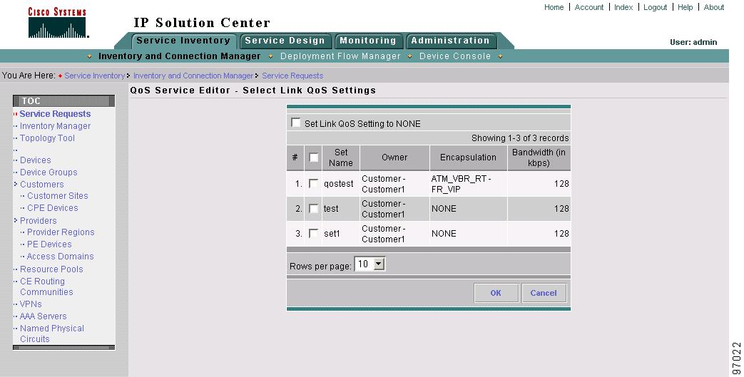
Figure 7-24 QoS Service Editor Select—Link QoS Settings
This window lists all set names (link QoS settings) previously defined in the link level QoS policy. See Defining the Link Level QoS Policy for more information.
Step 7
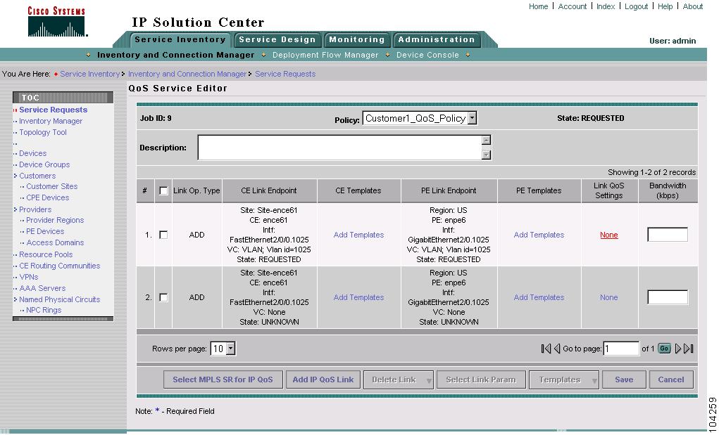
Figure 7-25 Completed QoS SR from MPLS SR
The CPE-PE links and link QoS settings for the QoS service request are listed. These are the QoS parameters that will be applied to the MPLS service request.
Step 8
Step 9
When the configlets are generated and downloaded to the devices, the QoS service request enters the Pending state. When the devices are audited, the QoS service request enters the Deployed state.
Note