Feedback
Table Of Contents
Prerequisites for QoS Provisioning
Traffic Classification Based on Variables
Prerequisites and Assumptions
To implement QoS parameters for a network using the Cisco IP Solution Center (ISC) 4.0, you must have specific configuration information about the devices participating in QoS provisioning.
This chapter describes how to check your devices for QoS configuration prerequisites, lists configuration and implementation assumptions, describes how to preconfigure certain QoS parameters using the ISC properties file.
Review all prerequisites and assumptions before you implement QoS provisioning.
This chapter contains the following sections:
•
Prerequisites for QoS Provisioning
•
Prerequisites for QoS Provisioning
ISC requires that you have certain pieces of configuration information about the devices participating in QoS provisioning. This configuration information can be obtained by ISC through one of the following three operations:
•
•
•
These operations are described in Cisco IP Solution Center Infrastructure Reference, 4.0.
Viewing Device Configuration
This section describes how to view the configuration for a device and determine if you have sufficient configuration information for QoS provisioning.
To view configuration information for a device:
Step 1
Step 2
Step 3
Step 4
Note
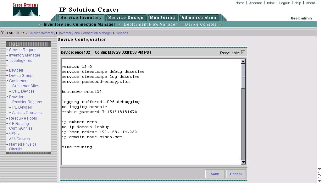
The Device Configuration window appears (Figure 4-1).
Figure 4-1 Device Configuration Example
This window shows the configuration information for the selected device.
Required Device Information
For QoS provisioning, you must also have the following device information. See System Requirements in Cisco IP Solution Center Installation Guide, 4.0 for specific configuration information.
•
•
•
•
•
Configuration Assumptions
This section describes device configuration assumption for QoS provisioning. These assumptions and other system requirements are further described in Cisco IP Solution Center Release Notes, 4.0.
All CPE and PE devices participating in a QoS provisioning service request must have the following as part of the initial configuration:
•
•
–
–
Note
ISC treats the global mls qos command as a prerequisite for Metro Ethernet QoS deployment. You must use this command to enable QoS on the Catalyst 3550. ISC does not automatically provision the mls qos command but requires it to be part of the initial configuration.
The mls qos command has a global effect on the switch and is not ever disabled by ISC. If you do not enable the QoS switch on the Catalyst 3550 with the mls qos command, all the QoS commands provisioned by ISC do download to the switch and the QoS service request does go to the DEPLOYED state. However QoS is not in effect until it is enabled with the mls qos command.
Implementation Assumptions
The QoS implementation model deployed in ISC is based upon the Differentiated Services (DiffServ) architecture. DiffServ describes a set of end-to-end QoS parameters that can be used in conjunction with Cisco IOS software, and allows the use of the differentiated service code point (DSCP) marking of the IP header. The DSCP header adds the capability of up to 64 service classes in a QoS policy.
ISC supports QoS provisioning in the context of the following:
•
•
•
ISC supports the following layer 2 encapsulations for QoS provisioning:
•
•
•
•
•
•
•
•
ISC supports the following Cisco IOS command structures for QoS provisioning:
•
•
–
–
–
–
Refer to the appropriate Cisco IOS documentation on Cisco.com for more information on Cisco IOS commands.
Editing the Properties File
The ISC Dynamic Component Properties Library (DCPL) file, which is the system properties file for ISC 4.0, contains several QoS-specific properties that can be preconfigured or edited prior to QoS provisioning.
The QoS configuration property in the DCPL file is the Management LAN Address
To edit QoS properties in the DCPL file:
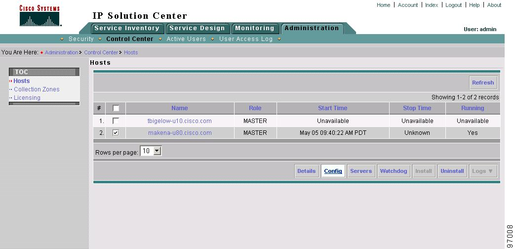
Step 1
Figure 4-2 ISC Hosts
The Host window lists ISC servers available for configuration edits.
Step 2
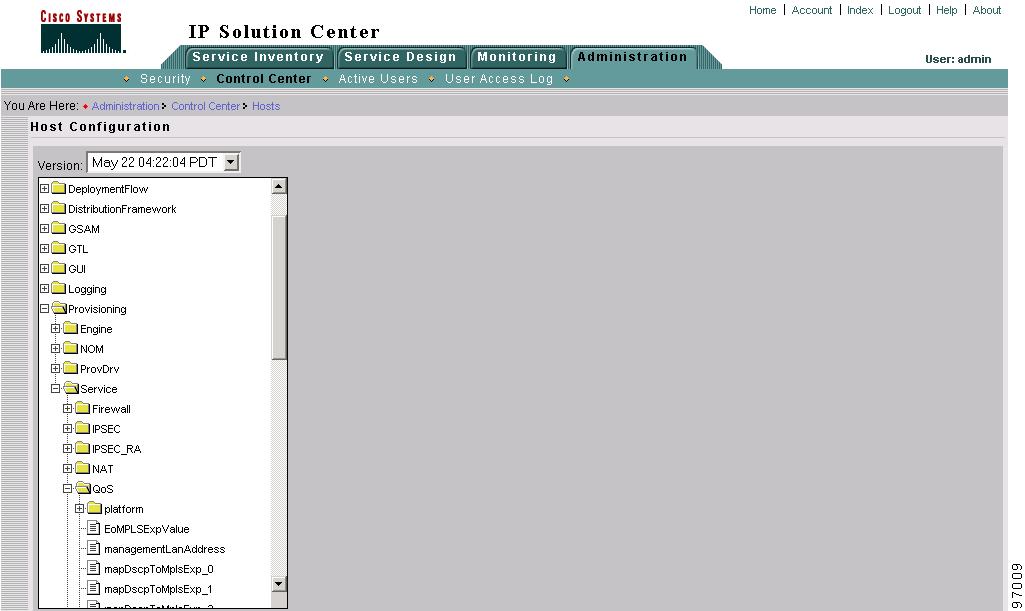
Figure 4-3 Host Configuration Files
This window displays the folder structure in the DCPL file. Each folder has a list of properties whose configurations can be edited.
This section describes the QoS configuration properties. For more information on other properties in the DCPL file, see Cisco IP Solution Center Infrastructure Reference, 4.0.
Step 3
Step 4
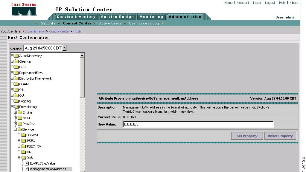
Figure 4-4 Host Configuration—Management LAN Address
Step 5
Enter the new management LAN address and subnet mask. This becomes the new default for the traffic classification field for the Management service class.
Step 6
Traffic Classification Based on Variables
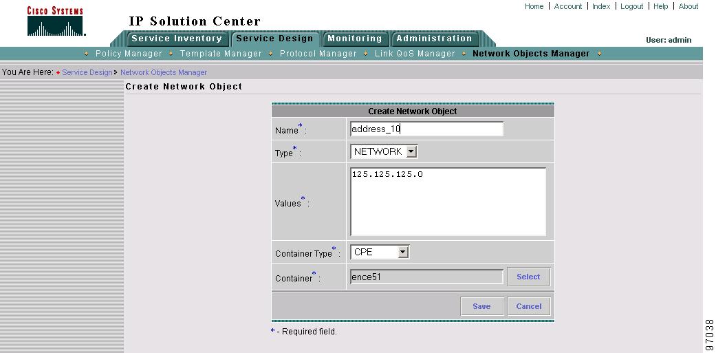
This section describes how to enter a variable containing a network address in the Network Objects Manager to be used later in the QoS provisioning process. This example describes how to classify traffic based on network addresses contained in variables, instead of based on protocols. You can then use this variable when configuring the traffic classification section within a service class.
To create network object variable:
Step 1
Step 2
Figure 4-5 Create Network Object
Step 3
For example, to configure a network address range, enter the following:
•
•
•
•
•
Step 4
This variable name (Address_10) is the value you enter in the Source field when configuring traffic classification based on addresses in a QoS service level policy. For more information on traffic classification based on addresses, see Traffic Classification.
The ISC configlet for this network address variable example becomes:
permit ip 125.125.125.0 0.0.0.255 anyInstead of:
match anyThe create network object variable feature can also be used by other ISC services.