-
Cisco Active Network Abstraction Managing MPLS User Guide, 3.6.5
-
preface.fm
-
Introducing MPLS VPN Maps
-
Creating and Manipulating VPN MPLS Maps
-
Creating and Manipulating Cisco ANA Business Configuration
-
Viewing VPN Properties In Service View
-
Viewing MPLS Related Inventory Properties
-
Fault Management In MPLS Networks
-
Calculating Impact Analysis
-
Working with PathTracer in VPN Service View
-
Running a VPN Leak Report Command
-
Additional Alarms
-
 Feedback
Table Of Contents
Working with PathTracer in VPN Service View
Cisco ANA PathTracer Tracing Capability
Opening Cisco ANA PathTracer Over MPLS Networks
Cisco ANA PathTracer Single-Path Window
Using PathTracer For Layer 3 VPN
Viewing Layer 3 Path Information
Using PathTracer For Layer 2 VPN
Viewing Layer 2 Path Information
Using PathTracer For MPLS Traffic Engineering Tunnels
Viewing MPLS TE Tunnel Information
Working with PathTracer in VPN Service View
This chapter describes the Cisco ANA PathTracer for Layer 2 and Layer 3 VPNs, and for MPLS Traffic Engineering tunnels, including opening the Cisco ANA PathTracer and viewing VPN and TE tunnel information in the PathTracer.
•
Cisco ANA PathTracer Tracing Capability—Provides a brief description of Cisco ANA PathTracer.
•
•
•
•
•
For more information about the Cisco ANA PathTracer, see the Cisco Active Network Abstraction 3.6.5 User Guide.
Cisco ANA PathTracer Tracing Capability
Based on its extensive, up-to-date knowledge of the network, Cisco ANA PathTracer traces service routes or network connectivity between two points in the network (or from a single starting point to an IP) providing performance information simultaneously for multiple networking layers along single as well as multiple routes. As it relies on the network model, end-to-end paths are provided across technologies and at different layers of the stack. It also displays various traffic and error statistics for each link and for each hop helping to pinpoint problems that may affect the service or cause service degradation.
Cisco ANA PathTracer immediately pinpoints and highlights exactly where the service affecting problems lie (namely, devices, slots, ports, protocol stacks, including comprehensive multi-layer status information with relevant configuration and traffic parameters). Cisco ANA understands and is able to display the various services on the network due to the up-to-date knowledge of the network.
Cisco ANA PathTracer enables the user to view multiple paths between the source and the destination (or from a source to number of destinations) in the Cisco ANA PathTracer Multi-Path window, or to view a selected single-path in the Cisco ANA PathTracer Single-Path window:
•
•
Opening Cisco ANA PathTracer Over MPLS Networks
You can open and view PathTracer information between service endpoints (for example, the IP interface which is attached to the VRF) over a MPLS network. The Label Switch Path (LSP) in the MPLS network is found according to the Cross Connect table of each router.
Note
In order to view a specific path you must specify an initial point like an IP interface and a destination IP address (optional). If the traced circuit (for example, VC, VLAN) ends in a router, Cisco ANA PathTracer finds the next hop according to the "destination IP address". When the user selects an endpoint the system extracts the relevant IP address from this point and uses it as the destination.
PathTracer Starting Points
The user can also enter the required destination IP address after opening the Cisco ANA PathTracer from the right-click shortcut menu. The table below describes the starting points available in the shortcut menu in order to open the PathTracer:
For information on opening Cisco ANA PathTracer from the Inventory window as starting point, see the Cisco Active Network Abstraction 3.6.5 User Guide.
PathTracer Endpoints
If you selected the "Start Here" option the following endpoints can be selected as a path destination to open the PathTracer:
The Cisco ANA PathTracer Multi-Path window is displayed. From this window you can open the Cisco ANA PathTracer Single-Path window with the appropriate VPN information displayed in the Layer 2 and Layer 3 tabs.
Note
Cisco ANA PathTracer Windows
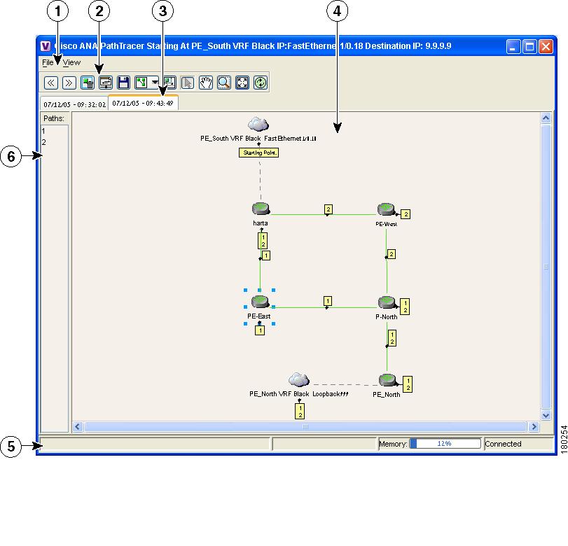
The Cisco ANA PathTracer Multi-Path window displays all the discovered paths for the selected context, including devices, links, and paths. For more information about opening Cisco ANA PathTracer, see Opening Cisco ANA PathTracer Over MPLS Networks.
The Cisco ANA PathTracer Multi-Path window enables you to perform the following functions:
•
•
•
•
Multi-path is the ability to display all the paths available between the selected source and destination.
An example of the Cisco ANA PathTracer Multi-Path window is displayed below.
Figure 8-1 Cisco ANA PathTracer Multi-Path Window
For a detailed description of the Cisco ANA PathTracer Multi-Path window, see the Cisco Active Network Abstraction 3.6.5 User Guide.
Cisco ANA PathTracer Single-Path Window
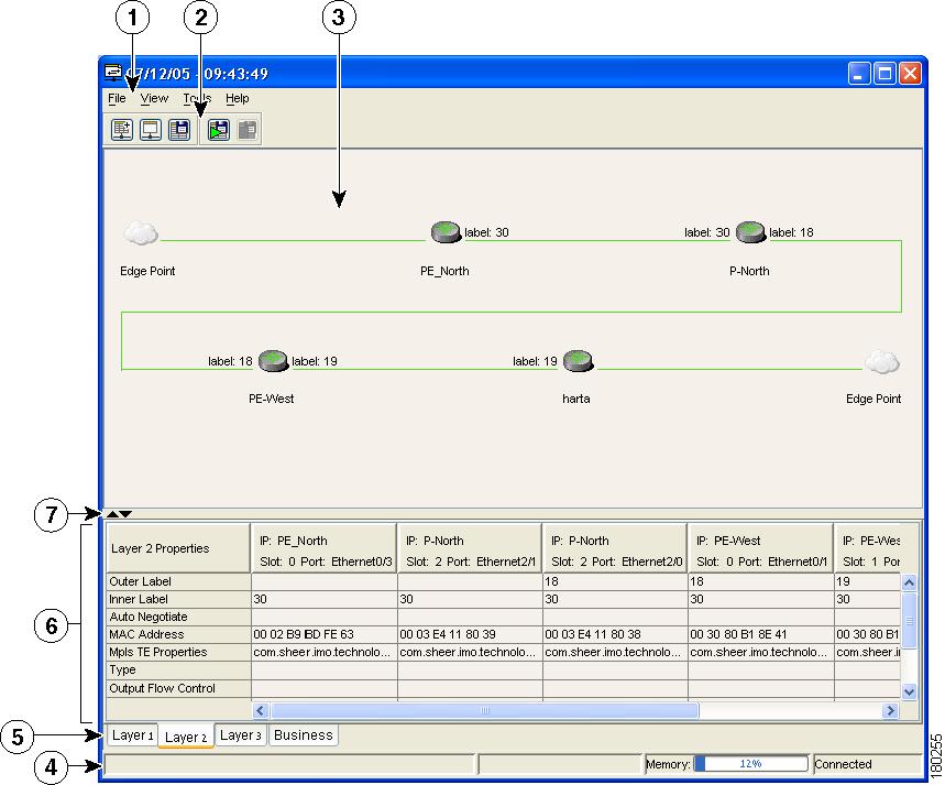
The Cisco ANA PathTracer Single-Path window displays the devices and links of the discovered path, as well as path layer Properties information in tables and subscribers.
The Cisco ANA PathTracer Single-Path window enables you to:
•
•
–
–
–
•
•
In addition, right-clicking an item in Cisco ANA PathTracer, enables you to perform certain functions. For example, you can view device information, namely, device properties and attach business tags.
An example of the Cisco ANA PathTracer Single-Path window is displayed below:
Figure 8-2 Cisco ANA PathTracer Single-Path Window
1
Menu bar
2
Toolbar
3
Map pane
4
Status bar
5
Layer tabs
6
Properties table
7
Hide/display Properties table
The Cisco ANA PathTracer Single-Path window displays information regarding each device. The information is either plain data that was extracted from the device or calculated data such as rates or statistics. The information is displayed in the Layer 1, Layer 2 and Layer 3 tabs.
In addition, the Cisco ANA PathTracer tabs display information regarding VPNs. The information is displayed in the Layer 2 and Layer 3 tabs.
For a detailed description of the Cisco ANA PathTracer Single-Path window, see the Cisco Active Network Abstraction 3.6.5 User Guide.
Using PathTracer For Layer 3 VPN
Cisco ANA Path Tracer uses VRF routing and label switching information in order to trace the path from one VRF interface to another.
By selecting a start and endpoint from the shortcut menu as described in Opening Cisco ANA PathTracer Over MPLS Networks, you can open the Cisco ANA PathTracer for Layer 3 VPNs.
The Cisco ANA PathTracer Multi-Path window is displayed showing the VPN topology map. From this window you can open the Cisco ANA PathTracer Single-Path window with the appropriate VPN information displayed in the Layer 2 and Layer 3 tabs.
Viewing Layer 3 Path Information
For Layer 3 path information Cisco ANA uses VRF routing and label switching information to trace the path from one VRF interface to another. Layer 3 PathTracer information is displayed in the Cisco ANA PathTracer window when the path goes over connections and ends in VRFs.
To view Layer 3 path information:
Step 1
Note
The Cisco ANA PathTracer Single-Path window with the Layer 3 tab is displayed.
The table displays the Layer 3 VPN information on the device that has a VRF. The following Layer 3 properties displayed in the Layer 3 tab relate specifically to VPNs:
•
•
•
•
•
•
PathTracer does not display or trace EXP bits for L3 VPNs that are using PBTS.
Using PathTracer For Layer 2 VPN
Cisco ANA uses VC ID and label switching information to trace the path from one tunnel interface to another over the MPLS network.
The Cisco ANA PathTracer also covers end-to-end Layer 2 VPN service paths from one customer edge (routers) to another, as part of Cisco ANA's capability of tracing service routes or network connectivity between two points in the network. The path goes over circuits (for example, a VC) or VLANs in the access networks and LSP between the Layer 2 tunnel edge.
For more information about Layer 2, see Viewing Layer 2 Path Information.
By selecting a start and endpoint from the shortcut menu, as described in Opening Cisco ANA PathTracer Over MPLS Networks, you can open the Cisco ANA PathTracer for Layer 2 VPNs.
The Cisco ANA PathTracer Multi-Path window is displayed showing the VPN topology map for the relevant devices and links. From this window you can open the Cisco ANA PathTracer Single-Path window with the appropriate VPN information displayed in the Layer 2 and Layer 3 tabs.
Viewing Layer 2 Path Information
For Layer 2 path information Cisco ANA uses VC ID and label switching information to trace the path from one tunnel interface to another. Layer 2 PathTracer information is displayed in the Cisco ANA PathTracer window when the path goes over PWE3 tunnels.
To view Layer 2 path information:
Step 1
Note
The Cisco ANA PathTracer Single-Path window with the Layer 2 tab is displayed.
The following Layer 2 properties that may be displayed in the Layer 2 tab relate specifically to VPNs:
•
•
•
•
•
•
•
•
•
•
•
•
Using PathTracer For MPLS Traffic Engineering Tunnels
Cisco ANA Path Tracer uses label switching information to trace the end-to-end path of a TE tunnel path from one PE router to another.
Using MPLS TE (Traffic Engineering) technology, Cisco ANA's PathTracer tool enables you to:
•
•
–
–
By selecting an IP destination from the shortcut menu as described in Opening Cisco ANA PathTracer Over MPLS Networks, you can open the Cisco ANA PathTracer for MPLS TE Tunnels.
The Cisco ANA PathTracer Multi-Path window is displayed showing the MPLS TE tunnel topology map. From this window you can open the Cisco ANA PathTracer Single-Path window with the appropriate MPLS TE tunnel information displayed in the Layer 2 tab.
PathTracer does not display or trace EXP bits for L3 VPNs that are using PBTS.
Viewing MPLS TE Tunnel Information
Layer 2 and Layer 3 PathTracer information is displayed in the Cisco ANA PathTracer windows when a path is traced over MPLS TE tunnels. This section specifically details Layer 2 TE tunnel properties.
To view Layer 2 path information:
Step 1
Note
The Cisco ANA PathTracer Single-Path window with the Layer 2 tab is displayed.
The following Layer 2 properties that may be displayed in the Layer 2 tab relate specifically to MPLS TE tunnels:
•
•
•
•
•
•
–
–
•
•
•
•
•
•
•
•
•
•
•
•
•
•