Table Of Contents
Calculating Impact Analysis
About Service Impact Analysis
Automatic Impact Analysis
Affected Severity
Proactive Impact Analysis
Service Impact Analysis For MPLS Based VPN Services
L3 VPN Report (VRFs As Affected)
Pseudo Wire (L2 VPN) Report (PWE3 Tunnels As Affected)
Supported Fault Scenarios
Link Down
Link Over Utilized/Data Loss
BGP Neighbor Loss
Supporting Route Reflector
Route Reflector Support
BGP Neighbor Loss Scenario 1
BGP Neighbor Loss Scenario 2
Broken LSP Discovered
MPLS TE Tunnel Down
Pseudo Wire (L2 VPN) MPLS Tunnel Down
Calculating Impact Analysis
This chapter provides an overview of the service impact analysis solution and supported scenarios, which are used in VPN networks that are based on MPLS, including Layer 3 and Layer 2 VPNs. In addition, it briefly describes proactive and automatic impact analysis.
•
About Service Impact Analysis—Describes the service impact analysis solution.
•
Service Impact Analysis For MPLS Based VPN Services—Describes the impact analysis process for Layer 3 VPN and Pseudo Wire (Layer 2 VPN) scenarios.
•
Supported Fault Scenarios—Describes the scenarios supported by the service impact analysis solution.
About Service Impact Analysis
Cisco ANA analyzes network faults in order to determine which network elements involved in the VPN services (such as interfaces on the PE) are affected or potentially affected by the fault.
Automatic Impact Analysis
When a fault occurs Cisco ANA automatically (this behavior can be configured by the user) generates the list of potential and actual service resources that were affected by a fault and embeds this information in the ticket along with all the correlated faults.
Note
Automatic impact analysis is not performed for every service alarm, but rather for small group of selected alarms, for example, BGP neighbor loss, broken LSP, link down, Layer 2 tunnel down and so on.
Affected Severity
When the impact analysis solution is automatic the affected parties can be marked with one of the following severities:
•
Potentially Affected—The service may be affected but it's real state is unknown.
•
Real Affected—The service is affected.
•
Recovered—The service is recovered. This state only relates to entries that were previously marked as potentially affected. It only indicates that there is an alternate route to the service, regardless of the service quality (level).
•
The initial impact report may mark the services as either Potentially Affected or Real Affected. As time progresses and more information is accumulated from the network the system may issue an additional report to indicate which of the potentially affected parties are Real Affected or Recovered.
•
The indications for these states are available both through the API and in the GUI.
Note
The reported impact severities vary between fault scenarios. For more information about specific support for each fault scenario, see Supported Fault Scenarios.
Note
When the alarm is cleared there is no Clear state for the affected services but the user can identify that the alarm was cleared by checking the Alarm Clear State column in the Affected Parties tab of the Ticket Properties window. For more information about the Affected Parties tab of the Ticket Properties window, see the Cisco Active Network Abstraction 3.6.5 User Guide.
For more information about automatic impact analysis, see the Cisco Active Network Abstraction 3.6.5 User Guide.
Proactive Impact Analysis
Cisco ANA provides `what-if' scenarios for determining the possible affect of network failures. This enables on-demand calculation of affected VPN Sites for physical links in the network, thus enabling an immediate service availability check and analysis for potential impact and identification of critical network links. Upon execution of the `what-if' scenario, the Cisco ANA fabric initiates an end-to-end flow, which determines all the potentially affected edges in the affected VPNs.
•
The proactive impact analysis solution is available in the:
•
Link Properties dialog box when selecting a physical link
•
Topological Link Properties window when selecting a physical link in the Links View.
•
For more information about proactive impact analysis, see the Cisco Active Network Abstraction 3.6.5 User Guide.
Service Impact Analysis For MPLS Based VPN Services
A MPLS network with Provider Edge (PE) routers is supported, where the PE routers implement either of the following:
•
L3 VPN (RFC2547)
•
Pseudo Wire - L2 VPN
Each scenario is described separately.
Note
The description provided in this chapter refers only to faults in the MPLS core and not to faults in access networks.
L3 VPN Report (VRFs As Affected)
When affected parties are generated using the impact solution the VRFs are displayed as the affected parties on the PE routers that lost connectivity between them in the Ticket Properties window.
Note
There is an option available in the registry to report on the IP interfaces which are attached to the VRFs as the affected parties as well. Changes to the registry should be performed only with the support of Cisco. For details, contact the Cisco Project Manager or Cisco Account Team.
The number of affected parties that are reported are calculated from the pairs of VRFs and are reported in the Ticket Properties window.
The structure of the edge points ID is Device ID \ VRF ID\ Subinterface (or interface) ID.
Note
In the structure described above "Subinterface (or interface) ID" is optional.
Note
VRF sites are not reported as affected pairs.
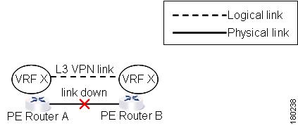
In the example below, there are two PEs A and B with the VRF X in the same VPN:
Figure 7-1 Layer 3 VPN Example
The Layer 3 VPN faults that are reported in this example are AX - BX.
Pseudo Wire (L2 VPN) Report (PWE3 Tunnels As Affected)
When a PWE3 tunnel goes down and an alarm occurs, the affected service resources are calculated by tracing the LSP to the edge of the PWE3 tunnel and collecting the affected pairs from both sides of the PWE3 tunnel. The edges of the tunnel are marked as affected.
The affected pairs are displayed in the Ticket Properties window. For more information about the Ticket Properties window, see the Cisco Active Network Abstraction 3.6.5 User Guide.
Supported Fault Scenarios
The following fault scenarios trigger automatic impact analysis calculation:
•
Link Down
•
Link Over Utilized/Data Loss
•
BGP Neighbor Loss
•
Broken LSP Discovered
•
MPLS TE Tunnel Down
•
Pseudo Wire (L2 VPN) MPLS Tunnel Down
The following criteria are used in the tables that are described in the sections that follow:
•
Impact Calculation—Describes the way in which the affected parties are calculated by system flows.
•
Reported Affected Severity—Describes the kind of severity generated by the alarm.
Note
Proactive impact analysis is only supported for links.
Link Down
Impact calculation
|
• Initiates an affected flow in order to determine the affected parties using the LSPs traversing the link.
|
Reported affected severity
|
• The "Link Down" alarm creates a series of affected severity updates over time. These updates are added to the previous updates in the system database. In this case the system provides the following reports:
– The first report of a "Link Down" reports on "X<->Y" as Potentially affected.
– Over time the VNE identifies that this service is Real affected or Recovered and generates an updated report (this only applies to cross-MPLS networks).
– The Affected Parties tab of the Ticket Properties dialog box displays the latest severity, namely, Real affected.
– The Affected Parties Destination Properties dialog box displays both reported severities.
This functionality is currently only supported for "Link Down".
|

Note
There is an option available in the registry to configure the real and recovered functionality. Changes to the registry should be performed only with the support of Cisco. For details, contact the Cisco Project Manager or Cisco Account Team.
Link Over Utilized/Data Loss
Impact calculation
|
Initiates an affected flow in order to determine the affected parties using the LSPs traversing the link.
|
Reported affected severity
|
Only reports on potentially affected.
|
BGP Neighbor Loss
Impact calculation
|
• Initiates a local affected flow to all VRFs that are present on the issuing device. Each local VRF which has route entries with a next hop IP that was learned from the BGP neighbor that was lost, collects VRFs from both sides and pairs them together as affected.
• Supports a Route Reflector configuration, whereby during the affected search, affected parties are located on all BGP neighbors learned via the Route Reflector.
|
Reported affected severity
|
Only reports on real affected on the IBGP domain.
|
Note
The "BGP Neighbor Loss" alarm represents a scenario where there is a BGP neighbor down.
Note
The affected only relate to L3 VPN services.
Supporting Route Reflector
Background—The Challenge of the Route Reflector:
BGP rules require that all routers within an autonomous system be fully meshed. For large networks, this requirement represents a severe scaling problem. Route reflectors enable a BGP entity to establish a single BGP connection with a peer, where through that single peer, routing information is learned from other peers. As a result the number of BGP sessions and connections is greatly reduced.
As a side effect of decreasing the amount of BGP connections, the presence of route reflectors also separates the data path and the control path. For example, data packets going from A to B do not go through the route reflector while the routing updates between A and B do.
Route Reflector Support
Each and every BGP router is uniquely identified by a router ID. A route reflector is not a configuration of a specific router. A router may act as a route reflector if it has a BGP neighbor configured as a BGP client. A router may act as both a route reflector to some of its BGP neighbors (those that are configured as BGP clients) as well as a non-client BGP neighbor to those BGP neighbors that are configured as non-client BGP neighbors.
A route reflector performs the following logic when distributing routes to its BGP neighbors:
•
A router will advertise to its client peers all routes learned from both other client and non-client peers.
•
A router will advertise to its non-client peers only routes received from client peers.
Router ID distribution follows the same logic described above.
Cisco ANA modeling provides for each interface, a list of one or more router IDs. This reflects the network behavior of receiving BGP updates from a BGP router (possessing that ID) through that interface.
The VNE also maintains the nature of the relationship (client and non-client) between the various VNEs representing the BGP routers.
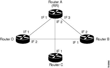
An example is displayed below.
Figure 7-2 Route Reflector Example
For example, in the setup above the following configuration is applied:
•
Router A (router ID A) has clients configured B, C and D. Therefore it serves as the route reflector for these BGP routers.
•
Routers B, C, and D all have Router A as a BGP non-client neighbor.
•
Router D and Router B also have each other configured as BGP nonclient neighbors.
In this case in Cisco ANA the following information is maintained by a VNE:
•
Router B learns router ID D from interface 1.
•
Router B learns router IDs (A, C, and D) from interface 2.
•
Router C learns router IDs (A, B, and D) from interface 1.
•
Router D learns router ID B from interface 2.
•
Router D learns router IDs (A, B, and C) from interface 1.
•
Router A learns router ID D from interface 1.
•
Router A learns router ID C from interface 2.
•
Router A learns router ID B from interface 3.
BGP Neighbor Loss Scenario 1
A BGP connection has been lost from Router A to Router B:
•
Router A notifies both Routers C and D of a loss of router ID B.
•
Router C removes the ID of Router B from its tables and completely loses connectivity to it, resulting in real affected impact analysis.
•
Router D loses the ID of Router B learned from interface 1 but it still has Router B's ID that was learned through interface 2 therefore no impact analysis is performed.
BGP Neighbor Loss Scenario 2
A BGP connection is lost from Router B to Router D:
•
Router B does not notify Router A of its router ID loss because Router A is configured in Router B's tables as a non-client peer.
•
Router D does not notify Router A of its router ID loss because Router A is configured in Router D's tables as a non-client peer.
•
Router B notes that the ID of Router D is no longer learned through interface 1.
•
Router D notes that the ID of Router B is no longer learned through interface 2.
•
No impact analysis is performed.
Broken LSP Discovered
Impact calculation
|
Initiates an affected flow in order to determine all the affected parties using the LSP.
|
Reported affected severity
|
Only reports on real affected. When the link down is cleared, all the correlated broken LSP alarms are auto-cleared.
|
Note
There is an option available in the registry to configure broken LSP functionality. Changes to the registry should be performed only with the support of Cisco. For details, contact the Cisco Project Manager or Cisco Account Team.
MPLS TE Tunnel Down
Impact calculation
|
Initiates a flow to look for affected parties.
|
Reported affected severity
|
Only reports on real affected.
|
Note
The MPLS TE Tunnel Flapping fault scenario is a transitory state of flapping.
Pseudo Wire (L2 VPN) MPLS Tunnel Down
Impact calculation
|
Initiates a flow to look for the affected parties.
|
Reported affected severity
|
Only reports on real affected on the MPLS domain.
|