-
Cisco Active Network Abstraction Managing MPLS User Guide, 3.6.5
-
preface.fm
-
Introducing MPLS VPN Maps
-
Creating and Manipulating VPN MPLS Maps
-
Creating and Manipulating Cisco ANA Business Configuration
-
Viewing VPN Properties In Service View
-
Viewing MPLS Related Inventory Properties
-
Fault Management In MPLS Networks
-
Calculating Impact Analysis
-
Working with PathTracer in VPN Service View
-
Running a VPN Leak Report Command
-
Additional Alarms
-
 Feedback
Table Of Contents
Viewing VPN Properties In Service View
Viewing a Virtual Router's Properties
Displaying the VRF Egress/Ingress Adjacents
Viewing VRF Properties In the Inventory Window
Viewing Cross VRF Routing Entries
Working With the VPN Service Overlay
Viewing VPN Properties In Service View
This chapter describes viewing the properties of the various business elements, as follows:
•
Viewing VPN Properties—Describes how to view VPN properties.
•
•
•
•
Viewing VPN Properties
Cisco ANA enables the user to view the properties of the VPN business element.
To view VPN properties:
Step 1
The following field is displayed in the VPN Properties dialog box:
•
Note
•
Step 2
Viewing Site Properties
Cisco ANA enables the user to view the properties of a Site, including the interfaces that are configured on the PE. The properties that are displayed reflect the configuration that is automatically discovered from the device.
Note
To view Site properties:
Step 1
The following fields are displayed in the Router IP Interface Properties dialog box:
•
•
•
•
•
The Addresses table displays the details of the IP interfaces on the PE side. The Subnet column is a combination of the IP address and the subnet mask.
Step 2
Viewing a Virtual Router's Properties
Cisco ANA NetworkVision enables the user to view the route distinguisher, and the import and export policies for each VRF.
To view a Virtual Router's properties:
Step 1
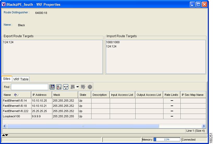
Figure 4-1 VRF Properties Dialog Box
The following field is displayed at the top of the VRF Properties dialog box:
•
The Export/Import Route Targets areas displayed in the VRF Properties dialog box specify separately the export and import policies for each VRF.
The VRF Properties dialog box is divided into two tabs, namely, the Sites and VRF Table tabs. The Sites tab displays the interfaces connected to the VRF and the configuration of the interfaces. The following columns are displayed in the Sites tab:
•
•
•
•
•
•
•
Note
•
Note
•
Note
•
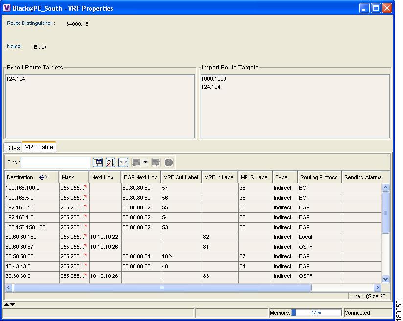
The VRF Table tab is displayed below.
Figure 4-2 VRF Table Tab
VRF Table tab contains the VRF routing table for the device, namely, a collection of routes that are available or reachable to all the destinations or networks in this VRF. In addition, the forwarding table also contains MPLS encapsulation information.
The following columns are displayed in the VRF Table tab:
•
•
•
•
•
•
•
•
•
•
Step 2
Opening the VRF Table
The user can view the VRF table for a Virtual Router.
To open the VRF Table:
Step 1
For more information about the columns displayed in the VRF Table dialog box, see Viewing a Virtual Router's Properties.
Step 2
Displaying the VRF Egress/Ingress Adjacents
Cisco ANA enables the user to view the exporting and importing neighbors by displaying the VRF egress and ingress adjacents. In addition, the user can view the connectivity between the VRFs regarding the route targets and view all their properties.
For example, if VRF A retrieved route target import X then the user will be able to view all the VRFs in the system that are exporting X as a route target whether its in the same VPN or in another VPN.
To display the VRF egress/ingress adjacents:
Step 1
The adjacents displayed are according to the route targets. The following columns are displayed in the table on the right side of the dialog box (properties pane) when the top branch is selected in the tree pane:
•
•
Selecting a specific VRF in the Cisco ANA NetworkVision window's tree pane the displays the properties of the VRF. For more information, see Viewing a Virtual Router's Properties.
Step 2
Viewing VRF Properties In the Inventory Window
This section describes viewing only the following VPN specific logical inventory items, namely, VRF and PWE3 Tunnels.
Note
For details on viewing the following VPN MPLS specific logical inventory items, namely, BGP Neighbor, MP BGP information, LSEs, and MPLS TE tunnels, and MPLS Black Holes, see Chapter 4 "Viewing VPN Properties In Service View".
To open the Inventory window:
Step 1
Step 2
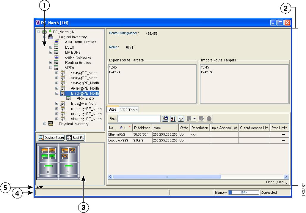
Figure 4-3 Inventory Window
The tree pane displays a tree and branch representation of the logical and physical inventory. The heading of the window and the root of the tree pane display the name of the selected router.
The properties pane displays physical and logical inventory information relating to the properties of the item selected in the tree pane.
Note
Step 3
You can view Inventory properties in the properties pane or properties pane tab tables, or view selected properties in separate window (Properties window).
Clicking a sub-branch tree pane option in the Inventory window displays the properties in the properties pane of the Inventory window:
Double-clicking a sub-branch tree pane option in the Inventory window, displays properties in a window.
Viewing Cross VRF Routing Entries
Cross VRF Routing entries are displayed by double-clicking an entry in the MP BGP properties pane. The Cross VRF Routing Entries table displays routing information learned from the BGP neighbors (BGP knowledge base). The parameters of the cross VRF routing entries are displayed in the Cross VRF MP BGP Properties window tab, an example of which is displayed.
The following information is displayed in the Cross VRF Routing Entries table:
•
•
•
•
•
•
Working With the VPN Service Overlay
In addition to Network and Service View maps the user can select and display an overlay of a specific VPN on top of the devices displayed on the Network map in the map pane. The overlay is a snapshot of the network which visualizes the flows between the Sites and tunnel peers When one of the VPNs in the network is selected (in the Network map), the provider edge routers, MPLS routers and physical links that carry the LSP that is being used by the VPN are highlighted in the Network map and all the devices and links that are not part of the VPN are grayed out.
This enables the user to isolate the parts of a network that are being used by a particular service and this information can then be used for troubleshooting. For example, the overlay can highlight configuration or design problems when a bottleneck exists and all the Site interconnections using the same link.
Note
Cisco ANA NetworkVision enables you to view overlays of specific VPNs on top of the devices displayed in physical Network maps. In addition, it enables you to view selected callouts for the links displayed on the Network map when the overlay is applied.
This section describes the following overlay functionality information:
•
•
•
Selecting an Overlay
The user may select and display an overlay of a specific VPN on top of the devices displayed on the physical Network map displayed in the map pane.
To select an overlay:
Step 1
Step 2
The Choose Overlay dialog box displays a list of the available VPNs in the network.
Step 3
Step 4
Note
You can choose to hide previously defined VPN network information in the map pane using the appropriate toolbar buttons:
•
•
Displaying or Hiding Overlays
The user can quickly and easily display or hide a previously defined overlay of a specific VPN on top of the physical devices displayed on the Network map in the map pane.
Note
To show or hide the overlay:
Step 1
Step 2
Displaying or Hiding Callouts
The user can display or hide the callouts for the links displayed in the map pane in order to show the details of the sites that are interconnected through the selected links.
Note
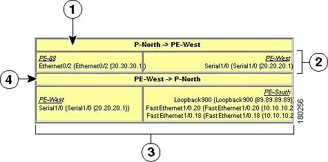
The Callouts dialog box enables the user to view the VPN traffic connections for a specific link (either bidirectional or unidirectional).
In the example below, P-North - > PE-West, the table displays the traffic connections from one Site/LCP to another.
Figure 4-4 Callouts Dialog Box
The user can hide the callouts displayed in the map pane.
To view the callouts:
Step 1
Step 2
To hide the callouts:
Step 1
Step 2