Table Of Contents
Viewing MPLS Related Inventory Properties
Introduction
Opening the Inventory Window
Viewing Routing Entities
Viewing the ARP Table
Viewing Rate Limit Information
Viewing Port Configuration
Viewing a LSE
Label Switching Table Tab
VRF Table Tab
LDP Neighbors Tab
Viewing MP BGP Information
Viewing BGP Neighbors
Viewing VRF Information
Opening the VRF Table
Viewing Cross VRF Routing Entries
Viewing Pseudo Wire End-to End Emulation (PWE3) Tunnels
Viewing MPLS TE Tunnel Information
Traffic Engineering LSPs
Viewing Access List Information
Viewing MPLS Related Inventory Properties
This chapter describes how to view general logical inventory information and describes the VPN specific items that are displayed in the Inventory window. For a general description of logical inventory and the Inventory window, see the Cisco Active Network Abstraction 3.6.5 User Guide.
•
Introduction—Introduces the concepts of physical and logical inventory.
•
Opening the Inventory Window—Describes how to open the Inventory window in order to view the logical inventory.
•
Viewing Routing Entities—Provides a brief description of the Routing Entities item. In addition, it briefly describes the ARP table.
•
Viewing Port Configuration—Provides a brief description of elements appearing in physical inventory branch that enable user determine what services, for example, are being used on a selected port.
•
Viewing a LSE—Describes the LSE item and its properties.
•
Viewing MP BGP Information—Describes the MP BGP item and its properties. In addition, it describes the BGP Neighbors item and properties
•
Viewing VRF Information—Describes the VRF item and its properties. In addition, it describes the import and export policies for each VRF.
•
Viewing Pseudo Wire End-to End Emulation (PWE3) Tunnels—Describes viewing the Layer 2 tunnel edge properties (per edge).
•
Viewing MPLS TE Tunnel Information—Describes the Traffic Engineering tunnel item and its properties.
•
Viewing Access List Information—Describes the Access List item and its properties, including access list entries.
Introduction
Every node that is managed by Cisco ANA is assigned to an autonomous VNE that manages it. The VNE continuously investigates the network element status and configuration in order to reflect it accurately and generate an accurate virtual model of the network.
The physical device inventory contains all the physical components (and their various properties) of the managed network element, such as chassis, shelves, cards and ports. The physical inventory is continuously updated for both status and configuration. Any change of status or addition or removal of a component (such as a card), is detected by the VNE and reflected in the network model instantly.
In addition to the physical network inventory, the Cisco ANA VNEs also investigate the logical inventory of each device. The logical inventory reflects dynamic data such as configuration data, forwarding and service-related components, which affects traffic handling in the device, such as traffic profiles, VC and cross-connect tables, routing, bridging, and LSE tables, and so on.
These logical device assets are also updated in the model of the network element in order to accurately reflect how the device handles its incoming and outgoing traffic.
Cisco ANA NetworkVision displays the device inventory and allows drill-down to detailed internal physical and logical inventory.
Opening the Inventory Window
The Cisco ANA solution continuously maintains a real-time, auto-discovered, physical and logical inventory of the network entities, and the relationships between them. Using Cisco ANA's distributed data model, the system automatically reflects every addition, deletion and modification that occurs in the network. The general logical inventory information displayed in the Inventory window changes according to the item selected in the tree pane.
This Guide describes viewing only the following VPN MPLS specific logical inventory items, namely, Routing Entities, LSE, BGP Neighbors, MP BGPs, VRFs, PWE3 tunnels, and TE tunnels.
Note
In addition to opening the Inventory window from a device, the user can also open and view logical inventory information for a specific Virtual Router directly by right-clicking the Virtual Router to display the shortcut menu and selecting Inventory.
To open the Inventory window:
Step 1
Right-click a device in the Cisco ANA NetworkVision window's tree pane or map pane to display the shortcut menu.
Step 2
Select Inventory. The Inventory window for the selected device is displayed.
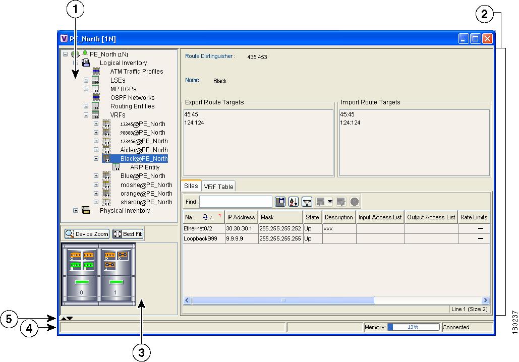
Figure 5-1 Inventory Window
1
|
Tree pane
|
2
|
Properties pane including tabs
|
3
|
Device View panel
|
4
|
Hidden ticket pane
|
5
|
Status bar
|
The tree pane displays a tree and branch representation of the logical and physical inventory. The heading of the window and the root of the tree pane display the name of the selected router.
The properties pane displays physical and logical inventory information relating to the properties of the item selected in the tree pane.
Note
The properties of the item selected in the tree pane or the row selected in the properties pane can be displayed by double-clicking it or by right-clicking the line and selecting Properties from the shortcut menu.
Step 3
Click to close the Inventory window.
Physical and logical inventory properties can be viewed in the properties pane (tabs or tables) or in a separate window (Properties dialog box).
•
Properties pane—Selecting a sub-branch in the tree pane of the Inventory window, displays the properties of the selected sub-branch in the properties pane of the Inventory window.
•
Properties dialog box—Double-clicking a sub-branch in the tree pane of the Inventory window, displays the properties of the selected sub-branch in a separate Properties dialog box.
Note
The examples used in this chapter are presented in the Properties dialog box, as described above.
Viewing Routing Entities
The Routing Entity sub-branch of the Routing Entities branch displays the IP interfaces and routing information.
The following information is displayed at the top of the Routing Entity - Routing Entity Properties dialog box (IP Interfaces):
•
Changes Number—The number of changes to the currently displayed routing entity.
•
Name—The name of the routing entity.
The Routing Entity Properties dialog box is divided into two tabs, namely, IP Interfaces and Routing Table tabs. The IP Interfaces tab lists the device IP interfaces and the Routing Table tab contains routing information.
The following information is displayed in the IP Interfaces tab:
•
Name—The name of the Site, for example, ATM4/0.100(10.0.0.1) is a combination of the interface name and IP address used to reach the Site.
•
IP Address—The IP address of the interface.
•
Mask—The details of the dotted decimal mask.
•
State—The state of the sub-interface, namely, Up or Down.
•
Description—A description of the interface.
•
Input Access List—If an access list is assigned to an IP interface it is available as a property of the IP interface, and a hyperlink highlights the related access list in the Access List table. When an access list is assigned to the inbound traffic on an IP interface, the actions assigned to the packet are performed. For information about actions see Viewing Access List Information.
Note
This parameter is only relevant for Cisco IOS devices.
•
Output Access List—If an access list is assigned to an IP interface it is available as a property of the IP interface, and a hyperlink highlights the related access list in the Access List table. When an access list is assigned to the outbound traffic on an IP interface, the actions assigned to the packet are performed. For information about actions see Viewing Access List Information.
Note
This parameter is only relevant for Cisco IOS devices.
•
Rate Limits—If a rate limit is configured on an IP interface it is available as a property of the IP interface. This option is checked when a rate limit has been defined on a specific IP interface of a device, meaning that the access list is defined as a rate limit access list. It measures traffic for the IP interfaces on Cisco devices, including the average rate, normal burst size, excess burst size, conform action and exceed action.
Note
Double-clicking a specific row displays the properties of the IP interface. When a rate limit has been configured on the IP interface the Rate Limits tab is displayed. For more information about rate limits see Viewing Rate Limit Information.
Note
This parameter is only relevant for Cisco IOS devices.
•
Site Name—The name of the business element to which the interface is attached.
•
Sending Alarms—This option is currently unavailable.
For more information about the IP Interfaces tab, see Viewing a Virtual Router's Properties, page 4-2.
The following information is displayed in the Routing Table tab:
•
Destination—The destination of the specific network.
•
Next Hop—The CE address from where to continue to get to a specific address. This field is empty when the routing entry goes to the PE.
•
Mask—The mask of the specific network.
•
Type—The type can be direct (local) or indirect.
•
Routing Protocol—The routing protocol used to communicate with other routers.
•
Sending Alarms—This option is currently unavailable.
•
Outgoing Interface Name—The name of the outgoing interface is displayed if the Routing Protocol type is local.
Viewing the ARP Table
The ARP Entity sub-branch of the Routing Entity branch displays ARP information.
The properties pane enables you to view MAC, interface, and IP address information. In addition, you can view the ARP type, namely:
•
Dynamic—An entry that has been learned by the device according to traffic in the network.
•
Static—An entry that has been learned by a local interface or by configuring a static ARP, like a static route.
•
Other—An entry that has been learned by another method which is not explicitly defined.
•
Invalid—In SNMP this is used to remove an ARP entry from the table.
Viewing Rate Limit Information
Select the Routing Entities > Routing Entity > IP Interfaces tab and double-click a specific row to display the properties of the IP interface. When a rate limit has been configured on the IP interface the Rate Limits tab is displayed.
Note
Rate limit information is only relevant for Cisco IOS devices.
The following information is displayed in the Rate Limits tab of the IP Interface Properties dialog box:
•
Type—The rate limit direction, namely, Input or Output.
•
Max Burst—Excess burst size in bytes.
•
Normal Burst—Normal burst size in bytes.
•
Bit Per Second—Average rate in bits per second.
•
Conform Action—The action that can be performed on the packet if it conforms to the specified rate limit (rule), for example, continue, drop, change a bit or transmit.
•
Exceed Action—The action that can be performed on the packet if it exceeds the specified rate limit (rule), for example, continue, drop, change a bit or transmit.
•
Access List—A hyperlink that highlights the related access list in the Access List table.
•
Sending Alarms—This option is currently unavailable.
Viewing Port Configuration
In addition to viewing logical inventory information in the Inventory window, when the user selects the physical source (port) in the physical inventory branch the user can determine what services are using the selected port. The user can view:
•
Physical layer information
•
Layer 2 information, for example, ATM and Ethernet
•
The sub-interfaces that the VRF is using.
For detailed information on viewing physical inventory information, see the Cisco Active Network Abstraction 3.6.5 User Guide.
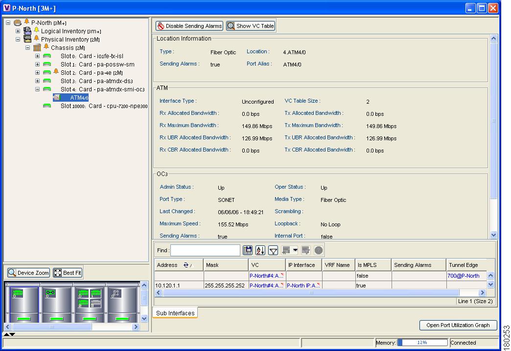
In the following example, port information (including the sub-interfaces), is displayed when a port is selected in the physical inventory branch of the Inventory window.
Figure 5-2 Port Information In the Inventory Window
The sub-interface is the logical interface defined in the device; all its parameters can be part of its configuration. The following information is displayed in the sub-interface table for the selected port:
•
Address—The IP address defined in the sub-interface.
•
Mask—The details of the dotted decimal mask.
•
VC—If the sub-interface is defined above an ATM or Frame-Relay physical interface and it uses a VC based encapsulation, it is the VC used in this encapsulation.
•
IP Interface—A hyperlink that displays the VRF properties in the Inventory window for the IP interface.
•
VRF Name—The name of the VRF.
•
Is MPLS—Whether this is a MPLS interface, namely, enabled (true) or disabled (false).
•
Sending Alarms—Whether the alarm for the required port has been enabled (true) or disabled (false).
•
Tunnel Edge—Whether this is a tunnel edge, namely, enabled (true) or disabled (false).
Viewing a LSE
The LSEs (Label Switch Entity) branch displays incoming and outgoing label information.
The Label Switching Properties dialog box may contain three tabs, which are described in the following sections:
•
Label Switching Table Tab
•
VRF Table Tab
•
LDP Neighbors Tab
Label Switching Table Tab
The Label Switching Table tab describes the MPLS label switching entries used for traversing the MPLS core networks.
The following information is displayed in the Label Switching Table tab:
•
Incoming Label—The details of the incoming MPLS label.
•
Action—The type of action, namely, POP, Swap, Aggregate, and untagged. When the action is defined as POP an outgoing label is not required. When the action is defined as untagged an outgoing label is not present.
•
Outgoing Label—The details of the outgoing MPLS label.
•
Out Interface—The name of the outgoing interface as a hyperlink that displays the physical inventory of the device, specifically the sub-interfaces of the port.
•
IP Destination—The IP address of the destination network.
•
Destination Mask—The mask of the destination network.
•
Next Hop—The IP Address of the next MPLS interface in the path. The IP address is used for resolving the MAC address of the next MPLS interface that we want to reach.
•
Sending Alarms—This option is currently unavailable.
When a TE Tunnel starts, the initial TE tunnel information can be viewed by selecting the LSEs/Label Switching sub-branch and viewing the information displayed in the Traffic Engineering LSPs tab. Later additional information, like bandwidth allocation can be viewed. For more information, see Traffic Engineering LSPs.
VRF Table Tab
The VRF Table tab describes all the MPLS paths that terminate locally at a VRF.
The following information is displayed in the VRF Table tab:
•
Incoming Label—The details of the incoming VRF label.
•
Sending Alarms—This option is currently unavailable.
•
VRF—The VRF name as a hyperlink that displays the VRFs properties.
LDP Neighbors Tab
The LDP Neighbors tab describes the details of all the peers of MPLS interfaces that use the LDP protocol.
LDP (Label Distribution Protocol) enables neighboring P or PE routers acting as label switch routers (LSRs) in an MPLS-aware network to exchange label prefix binding information which is required for forwarding traffic. The LSRs discover potential peers in the network with which they can establish LDP sessions in order to negotiate and exchange the labels (addresses) to be used for forwarding packets.
Two types of LDP peer discovery are supported:
•
Basic discovery—Used to discover directly connected LDP LSRs. An LSR sends hello messages to the "all routers on this subnet" multicast address, on interfaces for which LDP has been configured.
•
Extended discovery—Used between non directly connected LDP LSRs. An LSR sends targeted hello messages to specific IP addresses. Targeted sessions are configured since the routers are not physically connected, and broadcasting would not reach the peers. The IP addresses of both peers are required for extended discovery.
Note
If two LSRs are connected with two separate interfaces, two LDP discoveries are performed.
The following properties are displayed in the LDP Neighbors tab for each LDP peer:
•
LDP ID—The LDP identifier of the neighbor (peer) for the session.
•
Transport IP Address—The IP address advertised by the peer in the hello message or the hello source address.
•
Session State—The current state of the session, which may be one of the following:
–
Transient
–
Initialized
–
Open Rec
–
Open Sent
–
Operational
•
Protocol Type—The protocol used to establish the session, which may be LDP or TDP.
•
Label Distribution Method—The method of label distribution, which may be "Downstream" or "Downstream On Demand".
•
Session Keepalive Interval— The negotiated number of seconds between keepalive messages.
•
Session Hold Time—The amount of time (in seconds) that an LDP session can be maintained with an LDP peer, without receiving LDP traffic or an LDP keepalive message from the peer.
•
Discovery Sources—An indication of whether the peer has one or more discovery sources.
Note
You can see the discovery sources in the LDP Neighbor Properties window, by double-clicking the row of the peer in the table.
•
Sending Alarms—This option is currently unavailable.
Double-clicking an entry (peer) in the table opens the LDP Neighbor Properties window that displays the basic and targeted discovery sources for the peer. Each peer can have several discovery sources.
The following information is displayed in the LDP Neighbor Properties window for each discovery source:
•
Interface Name—The interface on which LDP is configured.
•
Source IP Address—The IP address of the peer that sends the targeted hello messages for extended discovery.
•
Adjacency Type—The type of LDP adjacency used for discovery, which may be "Link" (basic) or "Targeted" (extended).
•
Sending Alarms——This option is currently unavailable.
Viewing MP BGP Information
The MP BGPs branch displays the VRF name and cross VRF routing entries.
The following information is displayed in the MP BGPs - FW Component Container Properties dialog box:
•
Cross VRFs—The cross VRF routing entries are displayed if you double-click a row. For a description of the table displayed, see Viewing a Virtual Router's Properties, page 4-2.
•
MPBGP—The Multi Protocol BGP peer running on the local router.
•
Sending Alarms—This option is currently unavailable.
•
BGP Identifier—The local BGP router (ID of the local system) IP address used by the local BGP peer when advertising routing information.
•
Local As—The Autonomous System (AS) to which the BGP neighbor belongs.
•
BGP Neighbors—The table contains information on BGP entities that are known to the local BGP entity and exchange information with it.
Viewing BGP Neighbors
The MP BGP sub-branch, BGP Neighbors tab displays a list of the routers used in the BGP network, including, the configuration and status of the connections between the routers in the inventory and all the other BGP members (routers displayed in the table).
The MP BGP - MP BGP Properties dialog box is divided into two tabs, namely, Cross VRFs and BGP Neighbors tabs. The Cross VRFs tab is currently unavailable.
The BGP Neighbors tab displays a list of the routers used in the BGP network, including the configuration and status of the connections between the router displayed in the inventory, and all the other BGP members (routers displayed in the table).
The following information is displayed in the BGP Neighbors tab:
•
Peer Keep Alive—The time interval in seconds between successive KEEPALIVE messages. The BGP process negotiates the KEEPALIVE time with its neighbor upon establishment of the connection.
•
Peer Remote Address—The BGP peer remote IP address used by the BGP peer to exchange routing information with the local BGP peer.
Note
If the BGP peer is "Client" or "Non Client", the advertising policy is different for the different types of peers.
•
Peer State—The state of the connection between the local BGP peer to the remote BGP peer. Valid values are Idle, Connect, Active, Open Set, Open Confirm, and Established.
•
Sending Alarms—This option is currently unavailable.
•
Bgp Neighbor Type—Every BGP neighbor that is configured locally on a BGP router is either defined as a client or non-client type. Route reflector functionality is not specific behavior that is assigned to the device, but rather is defined according to the way that the BGP neighbor types are defined.
A route reflector performs the following logic when distributing routes to its BGP neighbors:
•
A router will advertise to its client peers all routes learned from both other client and non-client peers.
•
A router will advertise to its non-client peers only routes received from client peers.
For more information about route reflectors see Supporting Route Reflector, page 7-5.
•
Peer Hold Time—The BGP Hold Time value (in seconds) that is used when negotiating with peers. According to BGP specifications, if the router does not receive successive KEEPALIVE, UPDATE, or NOTIFICATION messages within the period specified in the Hold Time field of the OPEN message, then the BGP connection to the peer will be closed.
•
Peer Remote As—The autonomous system ID of the BGP neighbor.
•
Distribute through Interface—The local interface through which BGP information is distributed to BGP neighbors.
•
Peer Identifier—The IP address by which the BGP recognizes and converses with its neighbor.
Viewing VRF Information
Cisco ANA NetworkVision enables the user to view the VRF, and the import and export policies for each VRF.
Note
The Inventory window only displays VRF associations if they exist.
To view a VRF's properties:
Step 1
Right-click a VRF in the tree pane or map pane of the Cisco ANA NetworkVision window to display the shortcut menu.
Step 2
Select Properties. The VRF Properties dialog box for the VRF is displayed.
The following fields are displayed at the top of the VRF Properties dialog box:
•
Route Distinguisher—The route distinguisher configured in the VRF.
•
Name—The name of the VRF.
The Export/Import Route Targets areas displayed in the VRF Properties dialog box specify separately the export and import policies for each VRF.
The VRF Properties dialog box is divided into two tabs, namely, the Sites and VRF Table tabs. The Sites tab displays the interfaces connected to the VRF and the configuration of the interfaces. The following columns are displayed in the Sites tab:
•
Name—The name of the Site, for example, ATM4/0.100(10.0.0.1) is a combination of the interface name and IP address used to reach the Site.
•
IP Address—The IP address of the interface.
•
Mask—The details of the dotted decimal mask.
•
State—The state of the sub-interface, namely, Up or Down.
•
Description—A description of the interface.
•
Input Access List—The access list applied to the inbound traffic of the interface.
Note
This parameter is only relevant for Cisco IOS devices.
•
Output Access List—The access list applied to the outbound traffic of the interface.
Note
This parameter is only relevant for Cisco IOS devices.
•
Rate Limits—Measures traffic for the IP interfaces on Cisco devices, including the average rate, normal burst size, excess burst size, conform-action and exceed action.
•
Site Name—The name of the business element to which the interface is attached.
•
Sending Alarms—This option is currently unavailable.
The VRF Table tab contains the VRF routing table for the device, namely, a collection of routes that are available or reachable to all the destinations or networks in this VRF. In addition, the forwarding table also contains MPLS encapsulation information.
The following columns are displayed in the VRF Table tab:
•
Destination—The destination of the specific network.
•
Mask—The mask of the specific network.
•
Next Hop—The CE address from where to continue to get to a specific address. This field is empty when the routing entry goes to the PE.
•
BGP Next Hop—The PE address from where to continue to get to a specific address. This field is empty when the routing entry goes to the CE.
•
VRF Out Label—The label sent with MPLS traffic.
•
VRF In Label—The label that is expected when MPLS traffic is received.
•
MPLS Label—The MPLS label.
•
Type—The type can be direct (local) or indirect
•
Routing Protocol—The routing protocol used to communicate with the other Sites/VRFs, namely, BGP or local.
•
Sending Alarms—This option is currently unavailable.
•
Outgoing Int. Name—The name of the outgoing interface is displayed if the Routing Protocol type is local.
Step 3
Click to close the VRF Properties dialog box.
Opening the VRF Table
Cisco ANA NetworkVision enables you to view the VRF table for a VRF.
To open the VRF Table:
Step 1
Right-click the required VRF in the tree pane or map pane of the Cisco ANA NetworkVision window to display the shortcut menu.
Step 2
Select Open VRF Table. The VRF Table dialog box is displayed.
For more information about the columns displayed in the VRF Table dialog box see Viewing a Virtual Router's Properties, page 4-2.
Step 3
Click to close the VRF Table dialog box.
Viewing Cross VRF Routing Entries
The Cross VRF routing entries display routing information learned from the BGP neighbors (BGP knowledge base). The parameters of the cross VRF routing entries are displayed in the Cross VRF Properties dialog box.
The Cross VRF Routing entries are displayed by double-clicking an entry (row) in the Cross VRFs tab of the MP BGP Properties pane.
The following information is displayed in the Cross VRF Properties dialog box:
•
Destination—The destination of the specific network.
•
Mask—The mask of the specific network.
•
Next Hop—The PE address from where to continue to get to a specific address.
•
Out Going VRF—The VRF routing entry that points to the other VRF in the same PE. The Out Going VRF is the VRF that is pointed to by the Cross VRF entry.
•
Out Tag—The MPLS label inserted in the MPLS label stack by this PE router in order to reach the destination address that is connected to the other VRF.
•
In Tag—The MPLS label used by this router in order to identify traffic arriving at the destination address, it was advertised by this PE router and is inserted in the MPLS label stack by the PE from where the traffic originated.
•
Sending Alarms—This option is currently unavailable.
Viewing Pseudo Wire End-to End Emulation (PWE3) Tunnels
The Pseudo Wire Tunnels (PWE3) branch displays a list of the Layer 2 tunnel edge properties (per edge), including, tunnel status and VC labels.
The following information is displayed in the Tunnel Edges table:
•
Port—The name of the sub-interface or port.
•
Peer—The details of the selected LCP peer (edge peer).
•
Peer VC Label—The MPLS label that is used by this router to identify or access the tunnel. It is inserted in the MPLS label stack by the peer router.
•
Tunnel Status—The operational state of the tunnel, namely, up or down.
•
Local VC Label—The MPLS label that is used by this router to identify or access the tunnel. It is inserted in the MPLS label stack by the local router.
•
Local Router IP—The IP of this tunnel edge, which is used as the MPLS router ID.
•
Tunnel ID—The identifier that along with the router IPs of the two tunnel edges identifies the PWE3 tunnel.
•
Peer Router IP—The IP of the peer tunnel edge, which is used as the MPLS router ID.
•
Signaling Protocol—The protocol used by MPLS to build the tunnel, for example, LDP or TDP.
•
Sending Alarms—This option is currently unavailable.
For information on viewing Links in MPLS-TE (Traffic Engineering) tunnels see Chapter 7, "Calculating Impact Analysis" and Chapter 8, "Working with PathTracer in VPN Service View".
Viewing MPLS TE Tunnel Information
The Traffic Engineering Tunnels branch displays specific TE tunnel information on TE tunnels.
The name of the table is displayed at the top of the Properties window in the title bar. The following information is displayed in the Tunnel Edges table:
•
Name—The name of the TE tunnel (in Cisco devices it is the interface name).
•
Tunnel Destination—The IP address of the device in which the tunnel ends.
•
Administrative Status—The administrative state of the tunnel, namely, up or down.
•
Operational Status—The operational state of the tunnel, namely, up or down.
•
Outgoing Label—The TE tunnel's MPLS label distinguishing the LSP selection in the next device.
•
Description—A textual description of the tunnel.
•
Outgoing Interface—The interface through which the tunnel exits the device.
•
Bandwidth (Kbps)—Bandwidth specification for this tunnel.
•
Setup Priority—The tunnel's priority upon path setup.
•
Hold Priority—The tunnel's priority after path setup, when other tunnels try to remove it and claim its resources.
•
Affinity—The tunnel's preferential bits for specific links.
•
Affinity Mask—Dictates which bits from the tunnel's affinity should be compared to which bits of the link's attribute bits.
•
Auto Route—If enabled, destinations behind the tunnel are routed through the tunnel.
•
Lockdown—If enabled, the tunnel cannot be rerouted.
•
Path Type—The tunnel's path can be either dynamic, in which case, the tunnels is routed along the ordinary routing decisions after taking into account the constraints the tunnel imposes (attributes, priority, bandwidth) or explicit, in which case the route is explicitly plotted with included and excluded links.
•
Average Rate, Burst and Peak—Flow specification measured for this tunnel (in Kbps).
•
LSP ID—LSP identification number.
•
Sending Alarms—This option is currently unavailable.
•
EXP Bit—The MPLS Experimental bit used for PBTS traffic. This information is available only for Cisco CRS-1 routers running Cisco IOS XR 3.6 software in MPLS or MPLS VPN networks.
Traffic Engineering LSPs
The Label Switching sub-branch, Traffic Engineering LSPs tab displays TE tunnel LSPs information. Devices which have LSPs running TE tunnels (either as head-ends, mid-point or tail-ends), display tunnel information in the Traffic Engineering LSPs tab.
The following information is displayed in the Traffic Engineering LSPs tab:
•
LSP Type—The type of LSP:
–
Head—a tunnel starting in this device
–
Midpoint—a tunnel passing through this device
–
Tail—a tunnel terminating in this device
•
Source Address—IP address of the device in which the tunnel starts (where the tunnel's "head" is).
•
In Interface and Label—Occupied only for midpoint or tail LSPs, this label is advertised to the previous device on this interface as the LSP's next label.
•
Out Interface and Label—Occupied only for head or midpoint LSPs, this label will be appended to tunnel packets going out via this interface to the next hop along the tunnel's path.
•
Destination Address—The IP address of the device at the end of the tunnel.
•
LSP name—A name identifying the tunnel.
•
LSP ID—LSP identification number.
•
Average Bandwidth—Flow specification measured for this tunnel (in Kbps).
•
Burst—Flow specification measured for this tunnel (in Kbps).
•
Peak—Flow specification measured for this tunnel (in Kbps).
•
Sending Alarms—This option is currently unavailable.
Viewing Access List Information
The Access List branch enables users to classify and filter IP packets on inbound and outbound interfaces in the system. The Access List consists of a set of entries that define what traffic is permitted or denied access according to several parameters, such as IP subnet, protocol or port and so on. The Access List is defined by defining the access list on the device, and then adding the rules.
Note
Access limit information is only relevant for Cisco IOS devices.
Each row in the Access List table represents an access list. The following information is displayed in the Access List table:
•
Name—The name of the access list.
•
Type—The type of access list:
–
Standard—tests the source address (does not check for protocols)
–
Extended—tests the source and destination addresses as well as the TCP/IP protocols and source or destination ports
–
Named—the same as the standard and extended types described above, but has a string identifier
•
Access List Entries—Whether the access list has entries (checked) or not (unchecked).
•
Sending Alarms—This option is currently unavailable.
Double-clicking a row in the Access List table displays the entries of the list. The entries define what happens (permit or deny the action) when the rules are met. The following information is displayed in the Access List Properties dialog box:
•
Id—The identifier (name) of the access list entry.
•
Action—The type of action that will occur when the rules are met:
–
Permit—If the rules match, proceeds to the next rule. If all the rules are met then the packet is a match for the access list.
–
Deny—If the rules match, does not proceed to the next rule. The packet is not a match for the access list.
•
Protocol—The type of protocol that is checked, for example, IP, TCP, ICMP and so on.
•
Source—The IP source of the packet.
•
Source Wildcard—Defines the source range that will be included in the match using wildcard masking to identify whether to check (0) or ignore (1) corresponding IP address bits.
•
Source Port Action—Defines the action to be performed at the source port level. Examples of actions that can be performed are, the port number is equal to, or lower than or greater than x, where x is defined in the Source Port Range field.
•
Source Port Range—Defines the single source port or range of source ports to be checked according to the Source Port Action field.
•
Destination—The IP destination of the packet.
•
Destination Wildcard—Defines the destination range that will be included in the match using wildcard masking to identify whether to check (0) or ignore (1) corresponding IP address bits.
•
Destination Port Action—Defines the action to be performed at the destination port level. Examples of actions that can be performed are, the port number is equal to, or lower than or greater than x, where x is defined in the Destination Port Range field.
•
Destination Port Range—Defines the single destination port or range of destination ports to be checked according to the Destination Port Action field.
•
Precedence—The QoS of the IP packet for packet classification purposes, namely, TOS (Type of Service) or DSCP (Differentiated Services Code Point).
•
Protocol Specific—Whether this entry has additional specific protocol definitions (checked) or not (unchecked). The details of any additional protocol definitions can be viewed by double-clicking the required row (entry) in the Access List Properties dialog box. The Access List Entry Properties dialog box is displayed with the details, for example, if the protocol is ICMP, the Access List Entry Properties dialog box defines the exact message in ICMP, for example, echo (which is the ping request).
•
Matches—The number of packets matching the specific rule.
•
Sending Alarms—This option is currently unavailable.