-
Cisco Active Network Abstraction Managing MPLS User Guide, 3.6.5
-
preface.fm
-
Introducing MPLS VPN Maps
-
Creating and Manipulating VPN MPLS Maps
-
Creating and Manipulating Cisco ANA Business Configuration
-
Viewing VPN Properties In Service View
-
Viewing MPLS Related Inventory Properties
-
Fault Management In MPLS Networks
-
Calculating Impact Analysis
-
Working with PathTracer in VPN Service View
-
Running a VPN Leak Report Command
-
Additional Alarms
-
 Feedback
Table Of Contents
Introducing the Cisco ANA Business Configuration
Layer 3 VPN Business Configuration
Layer 2 VPN Business Configuration and Tunnels
Introducing MPLS VPN Maps
This chapter provides an introduction to the Service View, business configuration, and Service View maps, as follows:
•
Introducing VPN MPLS Maps—Describes Service View maps, including the concepts of VPN topology.
•
•
•
For a more detailed description of the Cisco ANA NetworkVision window, menus, and toolbars, and working with tables, see the Cisco Active Network Abstraction 3.6.5 User Guide.
Note
Introducing VPN MPLS Maps
Cisco ANA automatically discovers VPN services and provides a view of their configuration and topology (Service View map), in addition to discovering the physical and logical inventory of the devices (Network maps). Multiple maps may exist in the Cisco ANA system.
The VPNs that are discovered and displayed in Service View maps enable the user to drill down into specific VPNs and view information about the business elements contained in each VPN. For more information, see Introducing the Cisco ANA Business Configuration.
Note
Cisco ANA has the capability to automatically determine the different Layer 3 VPNs in the network and their associated Virtual Routers. For more information, see Layer 3 VPN Business Configuration.
After creating a Service View map the user can, for example:
•
•
•
The Service View also enables the user to:
•
•
•
•
•
•
•
Introducing the Cisco ANA Business Configuration
Cisco ANA supports the mapping of service related information to the network resources. This mapping is achieved using a business element that is a wrapper to a network element or service.
The VPN is a business element, which represents a set of interconnected Sites forming a single virtual private network over a public network. Sites can be inter-connected either over VRF or through a collection of PWE3 tunnels that relate to one customer.
Cisco organizes the business elements in a way that creates a containment hierarchy that reflects the VPN structure. For more information about the Layer 3 VPN hierarchy, see Layer 3 VPN Business Configuration and for more information about the Layer 2 VPN hierarchy, see Layer 2 VPN Business Configuration and Tunnels.
Business elements are available via the Northbound interface as well as in Cisco ANA NetworkVision.
Any changes that are made to the business configuration are reflected in all maps. For example, if a link is removed this change will be reflected in all the maps.
Layer 3 VPN Business Configuration
The following business elements are used to represent the Layer 3 VPN configuration:
•
•
The Layer 3 VPN configuration hierarchy is composed of VPN business elements that in turn contain multiple Virtual Routers and Sites. The relationship between the contents of VPNs and Virtual Routers can be changed, for example, by moving a Virtual Router between VPNs, which causes each Site connected to the moved Virtual Router to move as well. The relationship between Virtual Routers and Sites cannot be changed; as Sites are automatically attached to Virtual Routers (Sites cannot be moved on their own).
In the Layer 3 VPN configuration the VPNs are created and named automatically and new Virtual Routers are automatically detected. The Virtual Router is then automatically related or matched to the VPN based on the VRF name. If there is no related or matching VPN, then a new VPN is automatically created and a VRF is assigned to it. The user can then add these VPNs to a map. The user can manually change the auto-discovered service information, for example, by manually creating new VPNs, by deleting empty VPNs, or by renaming VPNs and so on.
Cisco ANA can use different criteria in order to determine the different Layer 3 VPNs in the network and their associated Virtual Routers. By default, Cisco ANA uses the most intuitive criterion - the VRF name in order to deduce the VPNs on the network.
It is possible to change this criterion to fit specific environments through Cisco's Project Manager or Cisco Account Team, and it can be modified to reflect virtually any criteria. A common change is to identify VPNs by specific Route Distinguisher (RD) bits.
Layer 2 VPN Business Configuration and Tunnels
In Layer 2 VPN there is no automatic creation of VPNs. You can create the VPNs and then add the tunnels. The following business elements are used to represent the Layer 2 VPN configuration:
•
Note
•
LCAs can be manually or automatically created:
•
•
For more information about creating LCAs, see Creating an LCA, page 3-5.
VPN Topology Connections
Cisco uses route targets (based on the router configuration) to determine the topology between VRFs. Layer 3 VPN topology information is continuously updated to reflect the actual state of the network connections.
Cisco uses the VC ID and the Router IP address (based on the router configuration) to determine the connectivity between the Layer 2 tunnel edges forming the PWE3 tunnels.
The current version reflects the actual state of the tunnel (up/down) for the logical link in Layer 2 topology (if it has already been discovered). The link is displayed with a minor severity (yellow) on the map when the tunnel is down.
The different kinds of topology that may be displayed on the Service View map are described in the following tables:
Note
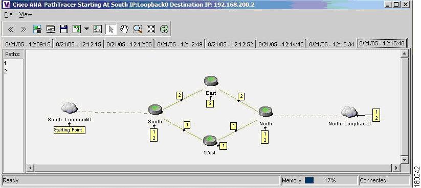
The example below displays several devices that are connected in a multipath VPN MPLS map in the Cisco ANA PathTracer Multipath window:
Figure 1-1 Cisco ANA PathTracer Multipath Window
For more information about the icons displayed in the maps of the Cisco ANA NetworkVision window, see Table 1-3.
In addition to the topology described previously, the associations described in the table below may also be displayed on the Service View map:
Table 1-2 Associations
•
•
•
•
•
•
VPN Service View Map
Cisco ANA automatically discovers VPN services and provides a view of their configuration and topology (VPN Service View map), in addition to discovering the physical and logical inventory of the devices (Network maps).
Layer 3 VPN Service View Map
The Service View map presents existing Layer 3 VPNs in the network. At the top level, the user can see inter-VPN (Extranet) connections. Drilling down into each VPN presents the Service View map, with the following:
•
•
•
Layer 2 VPN Service View Map
For Layer 2 VPNs the Service View map presents existing Layer 2 VPNs in the network. At the top level, the user can see inter-VPN (Extranet) associations. Drilling down into each VPN presents the Service View map, with the following:
•
•
•
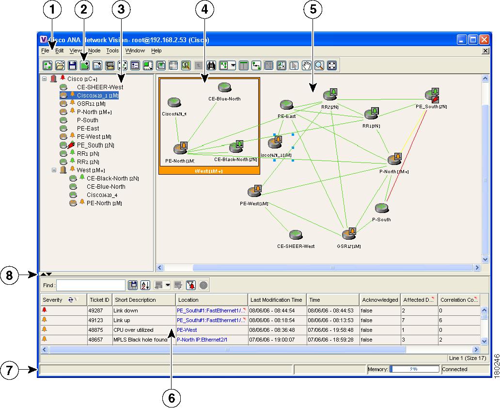
An example of the Cisco ANA NetworkVision window with an open Service View map is displayed below.
Figure 1-2 Cisco ANA NetworkVision Window
Menu bar
Toolbar
Tree pane
Aggregation
Workspace
Ticket pane
Status bar
Hide/display ticket pane buttons
The Cisco ANA NetworkVision window is divided into three areas or panes, as follows:
•
For a general description of the Cisco ANA NetworkVision window, menus and toolbar, see the Cisco Active Network Abstraction 3.6.5 User Guide.
Note
Tree Pane
The tree pane displays the business configuration for the VPN business elements, as described previously, in a tree and branch representation.
Each business element is displayed using an icon that has a color that reflects its severity and may have a management state icon or alarm. For more information, see the Cisco Active Network Abstraction 3.6.5 User Guide.
The following icons are used in the tree and map panes:
Table 1-3 Tree and Map Pane Icons
Root (map name) or aggregation
VPN business element
Virtual Router business element
Site business element
Site business element with an actively associated CE device and where the device is hidden
Logical Circuit Aggregator (LCA) business element
Logical Circuit Peer (LCP) business element
LCP business element with an actively assigned tunnel edge for the CE device and where the device is hidden
Note
In addition, the following management state icons are also used in Service View maps:
Table 1-4 Management State Icons
The reconciliation icon. The network element wrapped by this business element does not exist, for example, the device configuration has changed. Network problem.
The neighboring LCP does not exist or was not discovered. Stranded.
The highest level of the tree pane displays the root or map name. The branches display the VPN and aggregated business elements as well as their names.
The Layer 3 VPN sub-branches display the Virtual Routers and Sites contained in the VPN along with the names of the business elements. In addition, CE devices can also be displayed in the Layer 3 VPN subbranches.
The Layer 2 VPN sub-branches display the LCAs and LCPs contained in the VPN along with the names of the business elements. In addition, CE devices can also be displayed in the Layer 2 VPN subbranches.
When an aggregated business element is selected in the tree pane, the map pane displays the business elements contained within the aggregated business element.
Map Pane
The map pane displays the VPN business elements and aggregated business elements loaded in the Service View map along with the names of the business elements. In addition, the map pane displays the VPN topology (between the Virtual Routers in the VPNs) and the topology and associations between other business elements, as described on page 1-3.
When the root is selected in the tree pane the Service View map displays all the VPNs.
Ticket Pane
When Cisco ANA presents tickets related to the map, these tickets are displayed in the ticket pane enabling the user to view and manage the VPN tickets that have been generated by Cisco ANA. For more information about the alarms that Cisco ANA detects and reports for Layer 2 and Layer 3 VPNs, see Chapter 6, "Fault Management In MPLS Networks".
For more information about the ticket pane, see the Cisco Active Network Abstraction 3.6.5 User Guide.
In addition, the user can calculate the affected parties. For more information, see the Cisco Active Network Abstraction 3.6.5 User Guide.
Note