Feedback
Table Of Contents
C6576M NE Config/Mgmt Dialog Box
Backup/Restore Catalyst OS Image Area
Backup/Restore Configuration Area
Backup/Restore Configuration Area
802.1Q Trunk Remapped VLANs Area
VLAN Database Backup/Restore Area
C6576M EtherChannel Dialog Box
Global EtherChannel Ports Assignment Area
BGP Network Path Attribute Table Area
Edit Redistribution Table Area
Global Network Configuration Table
Edit Redistribution Table Area
Edit Redistribution Table Area
Edit Distribution List Table Area
Edit Redistribution Table Area
C6576M NDE Configuration Dialog Box
C6576M ACL Configuration Dialog Box
C6576M QoS Policy Map Dialog Box
Logical Object Dialog Boxes
This chapter describes the C65/76M dialog boxes for the logical objects. The following logical object dialog boxes are available in the C65/76M:
•
C6576M NE Config/Mgmt Dialog Box
•
•
•
•
Table 6-1 lists the pop-up menu launch points for all C65/76M dialog boxes.
C6576M NE Config/Mgmt Dialog Box
The C6576M NE Config/Mgmt dialog box provides monitoring and management information for properties related to the Catalyst 6000 family switch or Cisco 7600 series Internet Router. These properties include the Telnet and Enable passwords, global performance logging, and SNMP properties for the entire switch. This dialog box can be launched from a Network Element object within the Network or Physical views.
The Network Element object list (left-hand side of the dialog box) allows multiple objects to be selected, so that configuration changes can be applied to multiple Network Element objects at the same time.
Configuration Tab
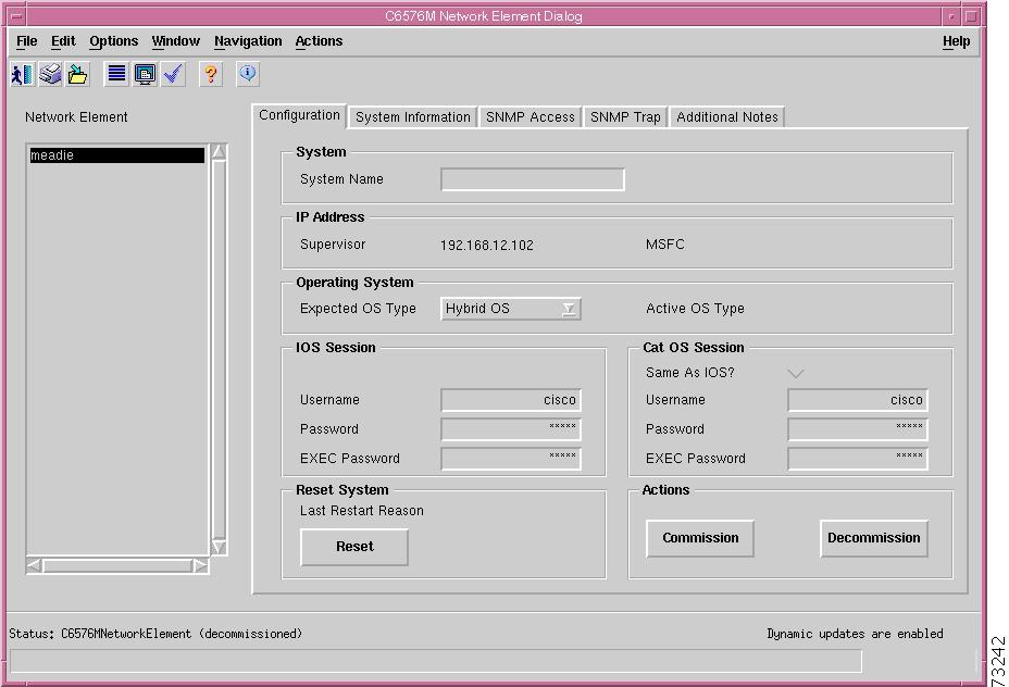
Figure 6-1 shows the Configuration tab of the C6576M Network Element dialog box.
Figure 6-1 Configuration Tab of the C6576M Network Element Dialog Box
System Area
The System area of the C6576M Network Element dialog box provides the following information:
•
IP Address Area
The IP Address area of the C6576M Network Element dialog box provides the following information:
•
•
Operating System Area
The Operating System area of the C6576M Network Element dialog box provides the following information:
•
•
IOS Session
The IOS Session area of the C6576M Network Element dialog box provides the following information:
•
•
•
Cat OS Session Area
The Cat OS Session area of the C6576M Network Element dialog box provides the following information:
•
•
•
•
Note
Reset System Area
The Reset System area of the C6576M Network Element dialog box provides the following information:
•
•
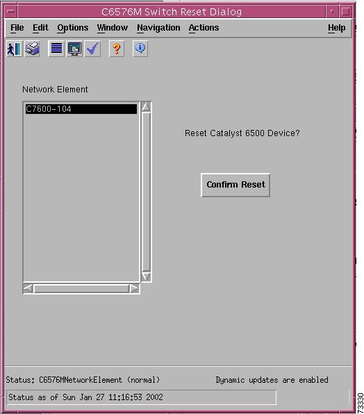
Note
Note
Figure 6-2 Confirmation Reset Window for a Network Element
Actions Area
The Actions area of the C6576M Network Element dialog box provides the following information:
•
•
Status Field
The display-only Status field located at the bottom of the window indicates the current state of the object. This field has the following values:
•
•
•
•
•
•
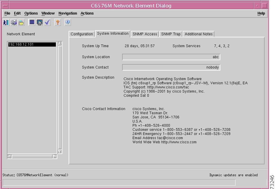
System Information Tab
Figure 6-3 shows the System Information tab of the C6576M Network Element dialog box.
The System Information tab provides the following information:
•
•
•
•
•
•
Figure 6-3 System Information Tab of the C6576M Network Element Dialog Box
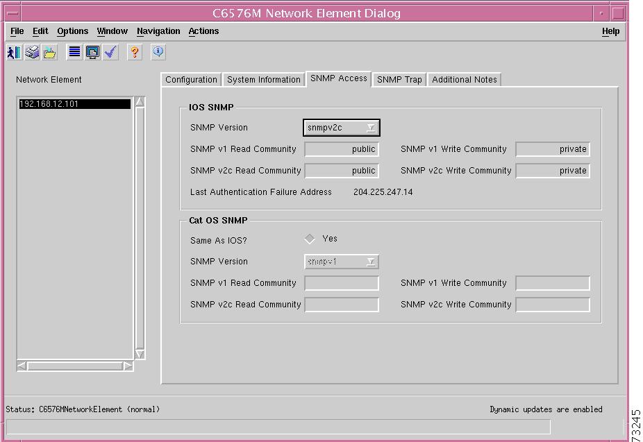
SNMP Tab
Figure 6-4 shows the SNMP tab of the C6576M Network Element dialog box.
Figure 6-4 SNMP Access Tab of the C6576M Network Element Dialog Box
IOS SNMP Area
The IOS SNMP area of the C6576M Network Element dialog box provides the following information:
•
–
–
–
•
•
•
•
•
Cat OS SNMP Area
The Cat OS SNMP area of the C6576M Network Element dialog box provides the following information:
•
•
–
–
–
•
•
•
•
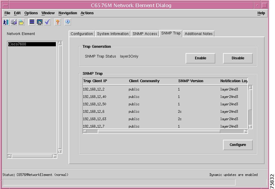
SNMP Trap Tab
Figure 6-5 shows the SNMP Trap tab of the C6576M Network Element dialog box.
Figure 6-5 SNMP Trap Tab of the C6576M Network Element Dialog Box
Trap Generation Area
The Trap Generation area of the C6576M Network Element dialog box provides the following information:
•
–
–
–
–
•
•
SNMP Trap Area
The SNMP Trap area of the C6576M Network Element dialog box provides the following information:
•
–
–
–
•
•
–
•
•
•
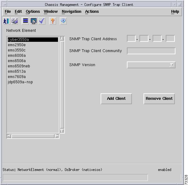
Note
•
–
–
–
–
Note
Figure 6-6 Configure Trap Client List Popup Window
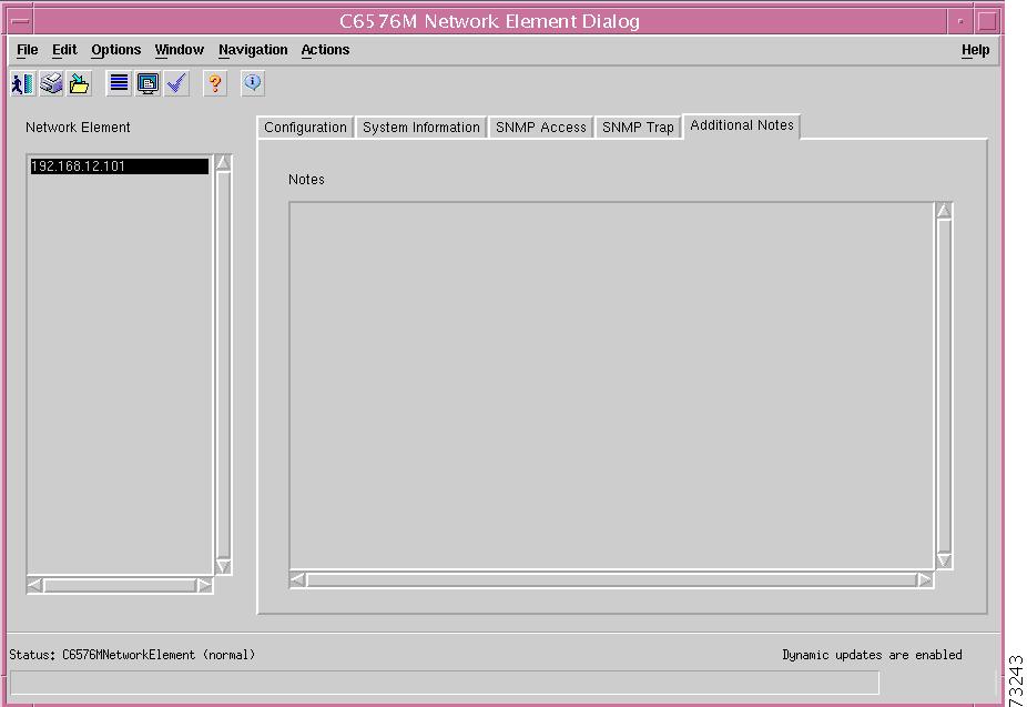
Additional Notes Tab
Figure 6-7 shows the Additional Notes tab of the C6576M Network Element dialog box.
Figure 6-7 Additional Notes Tab of the C6576M Network Element Dialog Box
Notes Area
The Notes area is a text box that allows you to type in additional notes. For example, this information can include text indicating why global performance logging is turned on.
C6576M Software Dialog Box
This dialog box provides information on the IOS image and configuration of the switch or router. This dialog box is launched from a Network Element object within the Network or Physical view and the Software object in the Physical view.
You can choose only one software object at a time from the object list on the left side of the dialog box.
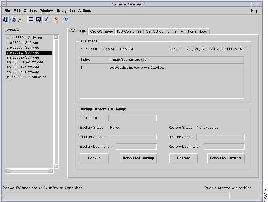
IOS Image Tab
Figure 6-8 shows the IOS Image tab of the C6576M Software dialog box.
Figure 6-8 IOS Image Tab of the C6576M Software Dialog Box
IOS Image Area
The IOS Image area of the C6576M Software dialog box provides the following information:
•
•
•
•
Backup/Restore IOS Image Area
The Backup/Restore IOS Image area of the C6576M Software dialog box provides the following information:
•
•
–
–
–
•
•
•
–
–
–
•
•
•
•
–
–
–
•
Note
•
–
–
–
Figure 6-9 Scheduled Backup/Restore IOS Image Dialog Box
Note
Status Field
The Status display-only field located at the bottom of the window indicates the current state of the object. This field has the following values:
•
•
•
•
•
Cat OS Image Tab
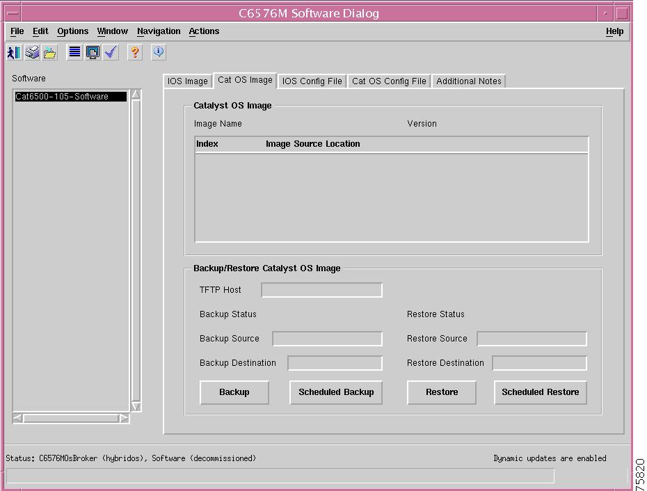
Figure 6-10 shows the Cat OS Image tab of the C6576M Software dialog box.
Figure 6-10 Cat OS Image Tab of the C6576M Software Dialog Box
Catalyst OS Image Area
The Catalyst OS Image area of the C6576M Software dialog box provides the following information:
•
•
•
Backup/Restore Catalyst OS Image Area
The Backup/Restore Catalyst OS Image area of the C6576M Software dialog box provides the following information:
•
•
–
–
–
•
•
•
–
–
–
•
•
•
•
–
–
–
•
Note
•
–
–
–
Figure 6-11 Scheduled Backup/Restore Cat OS Image Dialog Box
Note
IOS Config File Tab
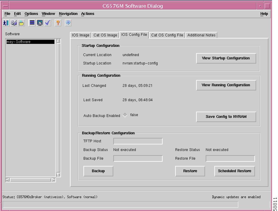
Figure 6-12 shows the IOS Config File tab of the C6576M Software dialog box.
Figure 6-12 IOS Config File Tab of the C6576M Software Dialog Box
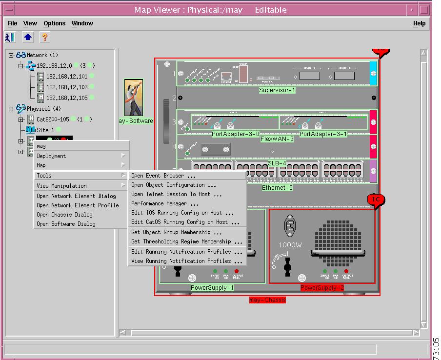
The running configuration file can be edited by selecting the pop-up menu option of the network element object, shown in Figure 6-13.
Figure 6-13 Pop-up Menu Option to Edit the Running Configuration File
Startup Configuration Area
The Startup Configuration area of the C6576M Software dialog box provides the following information:
•
•
•
Figure 6-14 Startup Configuration Window Action Report
Running Configuration Area
The Running Configuration area of the C6576M Software dialog box provides the following information:
•
•
•
•
•
Figure 6-15 Running Configuration Window Action Report
Backup/Restore Configuration Area
The Backup/Restore Configuration area of the C6576M Software dialog box provides the following information:
•
Note
•
–
–
–
•
Note
•
•
–
–
–
•
•
•
Note
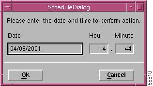
Figure 6-16 Scheduled Restore Configuration Dialog Box
The Scheduled Restore Configuration dialog box provides the following information:
•
•
•
Tip
Cat OS Config File Tab
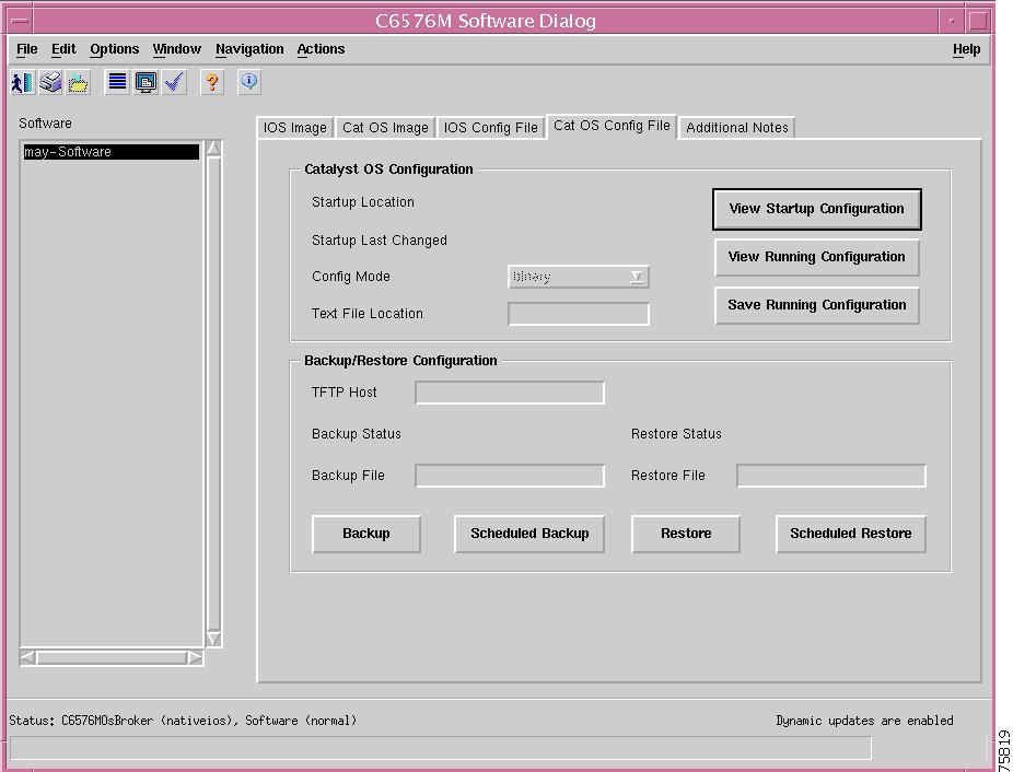
Figure 6-17 shows the Cat OS Config File tab of the C6576M Software dialog box.
Figure 6-17 Cat OS Config File Tab of the C6576M Software Dialog Box
The running configuration file can be edited by selecting the pop-up menu option of the network element object, shown in Figure 6-18.
Figure 6-18 Pop-up Menu Option to Edit the Running Configuration File
Startup Configuration Area
The Startup Configuration area of the C6576M Software dialog box provides the following information:
•
•
•
–
–
•
•
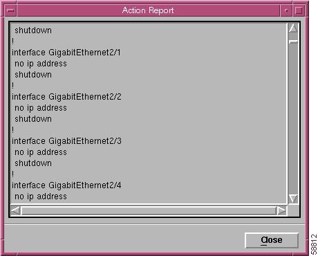
Figure 6-19 Startup Configuration Window Action Report
•
•
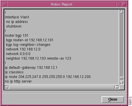
Figure 6-20 Running Configuration Window Action Report
Backup/Restore Configuration Area
The Backup/Restore Configuration area of the C6576M Software dialog box provides the following information:
•
Note
•
–
–
–
•
Note
•
•
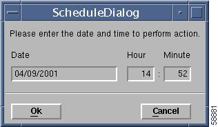
Figure 6-21 Scheduled Backup Configuration Dialog Box
The Scheduled Backup Configuration dialog box provides the following information:
•
•
•
Tip
•
–
–
–
•
•
•
Note
Figure 6-22 Scheduled Restore Configuration Dialog Box
The Scheduled Restore Configuration dialog box provides the following information:
•
•
•
Tip
Additional Notes Tab
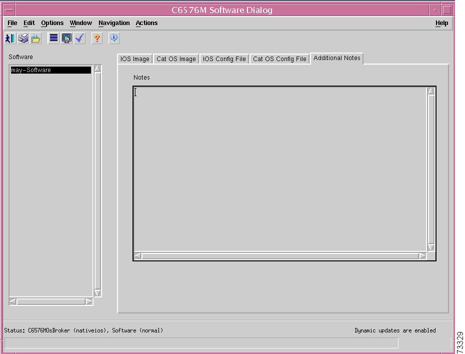
Figure 6-23 shows the Additional Notes tab of the C6576M Software dialog box.
Figure 6-23 Additional Notes Tab of the C6576M Software Dialog Box
Notes Area
The Notes area is a text box that allows you to type in additional notes for the object.
C6576M Syslog Dialog Box
This dialog box displays attributes for the system log messages on the switch or router. This dialog box can be launched from a Software object or Syslog object within the Physical view.
You can choose more than one Software object at a time from the object list on the left side of the dialog box.
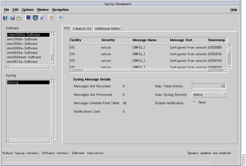
IOS Tab
Figure 6-24 shows the IOS tab of the C6576M Syslog dialog box.
The IOS tab provides the following information:
•
•
•
•
•
Note
Figure 6-24 IOS Tab of the C6576M Syslog Dialog Box
Syslog Message Details Area
The Syslog Message Details area of the C6576M Syslog dialog box provides the following information:
•
•
•
•
•
•
–
–
–
–
–
–
–
–
Note
•
–
–
Status Field
The Status display-only field located at the bottom of the window indicates the current state of the object. This field has the following values:
•
•
•
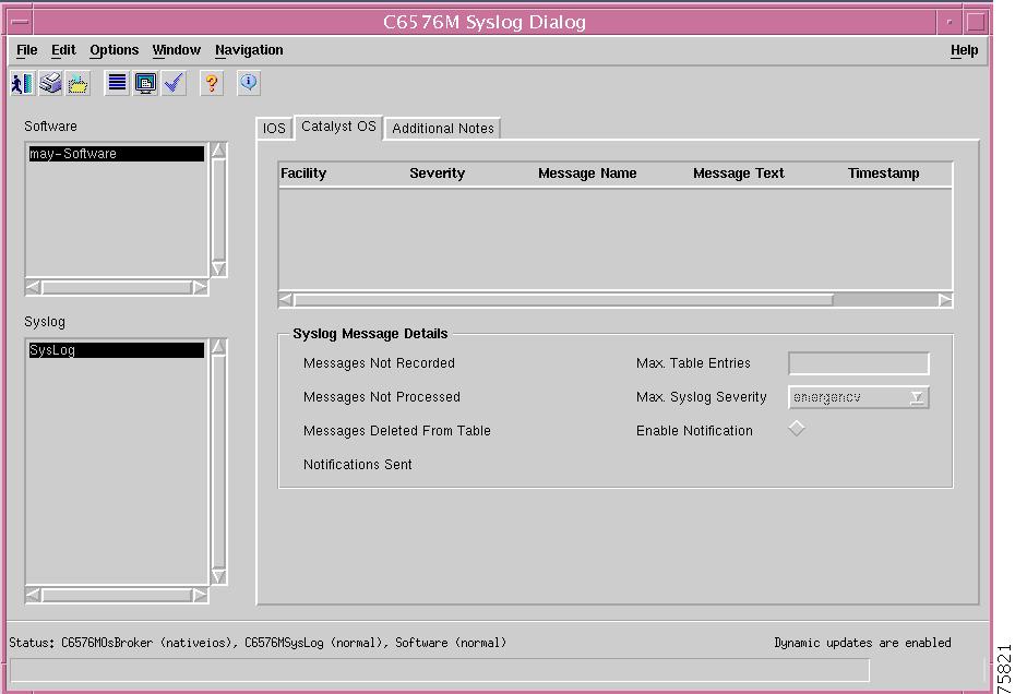
Catalyst OS Tab
Figure 6-25 shows the Catalyst OS tab of the C6576M Syslog dialog box.
The Catalyst OS tab provides the following information:
•
•
•
•
•
Note
Figure 6-25 Catalyst OS Tab of the C6576M Syslog Dialog Box
Syslog Message Details Area
The Syslog Message Details area of the C6576M Syslog dialog box provides the following information:
•
•
•
•
•
•
–
–
–
–
–
–
–
–
Note
•
–
•
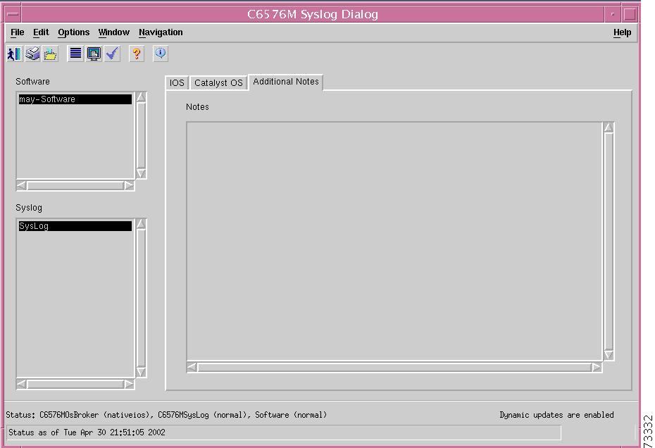
Additional Notes Tab
Figure 6-26 shows the Additional Notes tab of the C6576M Syslog dialog box.
Figure 6-26 Additional Notes Tab of the C6576M Syslog Dialog Box
Notes Area
The Notes area is a text box that allows you to type in additional notes for the object.
C6576M VTP Dialog Box
The VTP dialog box allows you to configure VTP domains on the switch or router. This dialog box can be launched from a Software object or VTP object within the Physical view.
You can choose more than one Software object at a time from the object list on the left side of the dialog box.
Details Tab
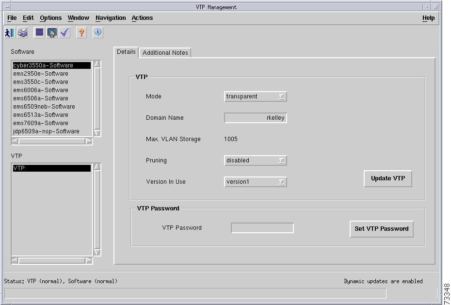
Figure 6-27 shows the Details tab of the C6576M VTP dialog box.
Figure 6-27 Details Tab for the C6576M VTP Dialog Box
VTP Area
The VTP area of the C6576M VTP dialog box provides the following information:
•
–
–
–
Note
•
•
•
•
•
Note
Note
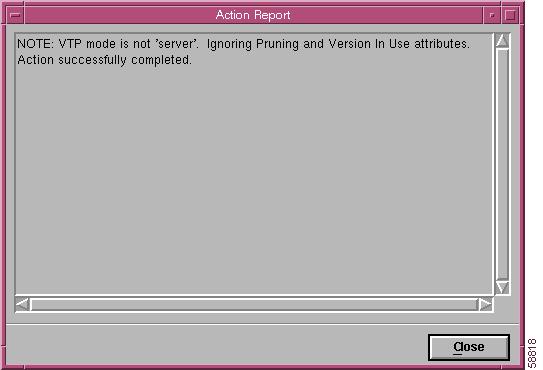
Note
Figure 6-28 Update Button Selected in Client Mode Message
Status Field
The Status display-only field located at the bottom of the window indicates the current state of the object. This field has the following values:
•
•
•
Additional Notes Tab
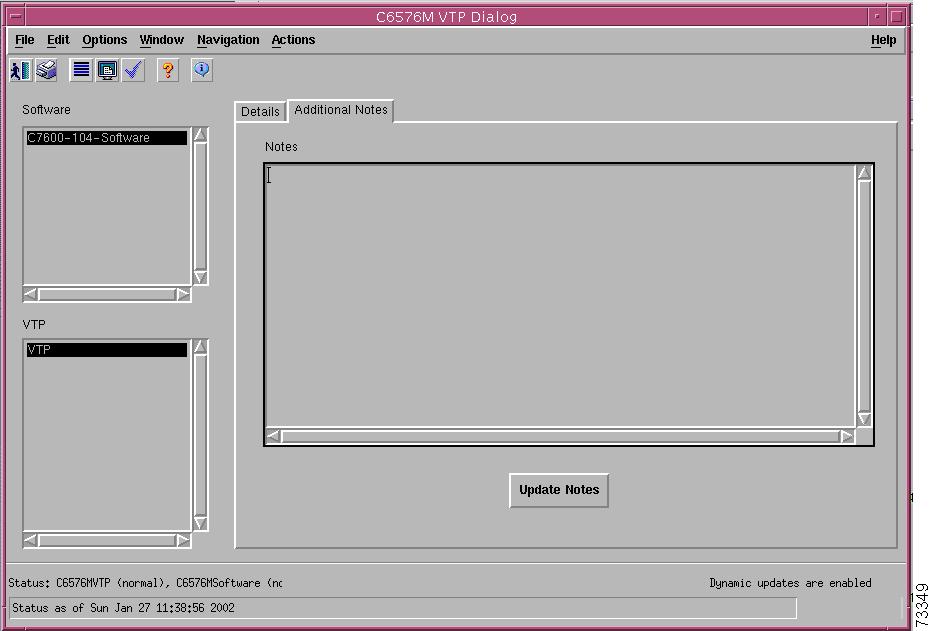
Figure 6-29 shows the Additional Notes tab of the C6576M VTP dialog box.
Figure 6-29 Additional Notes Tab of the C6576M VTP Dialog Box
Notes Area
The Notes area is a text box that allows you to type in additional notes for the object.
C6576M VLAN Dialog Box
This dialog box provides attributes for VLAN configurations. This dialog box can be launched from the Software object or VLAN object in the Physical view.
You can choose only one Software object and one VLAN object at a time from the object list on the left side of the dialog box.
Status Tab
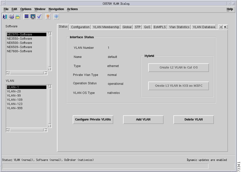
Figure 6-30 shows the Status tab of the C6576M VLAN dialog box.
Figure 6-30 Status Tab for the C6576M VLAN Dialog Box
Interface Status Area
The Details area of the C6576M VLAN dialog box provides the following information:
•
•
•
•
–
–
–
•
•
–
–
–
–
•
•
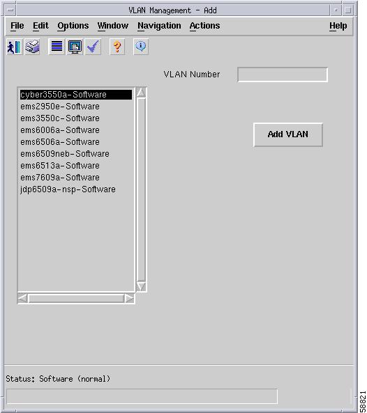
•
Specify the VLAN number to be added and click the Add VLAN button. The string VLAN- will prepended to the VLAN number specified.
Note
Figure 6-31 Add VLAN Subdialog Box
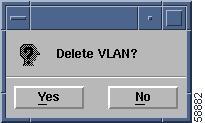
•
Figure 6-32 Delete VLAN Subdialog Box
Status Field
The Status display-only field located at the bottom of the window indicates the current state of the object. This field has the following values:
•
•
•
Configuration Tab
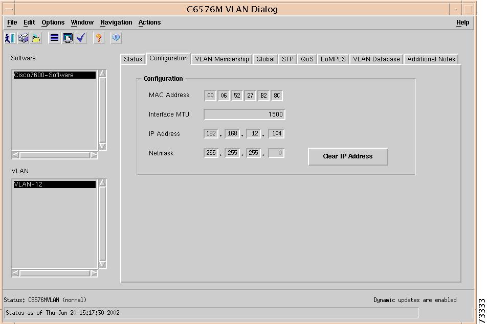
Figure 6-33 shows the Configuration tab of the C6576M VLAN dialog box.
Figure 6-33 Configuration Tab for the C6576M VLAN Dialog Box
Configuration Area
•
Note
•
Note
•
•
•
VLAN Membership Tab
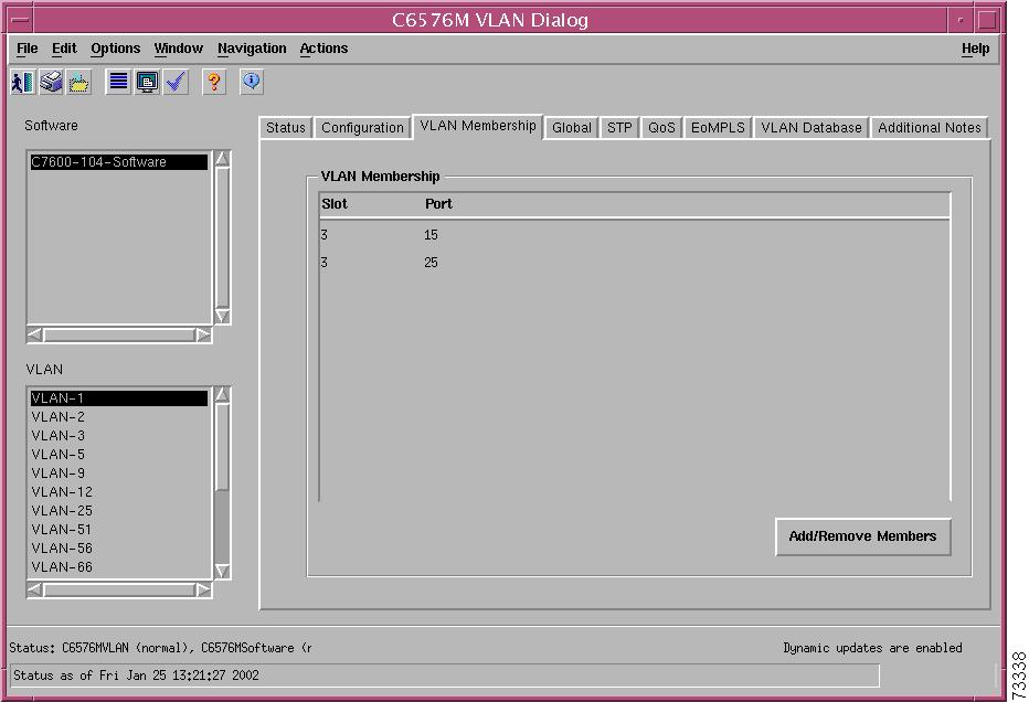
Figure 6-34 shows the VLAN Membership tab of the C6576M VLAN dialog box.
Figure 6-34 VLAN Membership Tab for the C6576M VLAN Dialog Box
VLAN Membership Area
The VLAN Membership area displays the members of this VLAN.
•
•
Specify the slot and port number of the interface that you want to add to the VLAN or delete from the VLAN.
Figure 6-35 Add/Remove VLAN Members Subdialog Box
Global Tab
Figure 6-36 shows the Global tab of the C6576M VLAN dialog box.
Figure 6-36 Global Tab of the C6576M VLAN Dialog Box
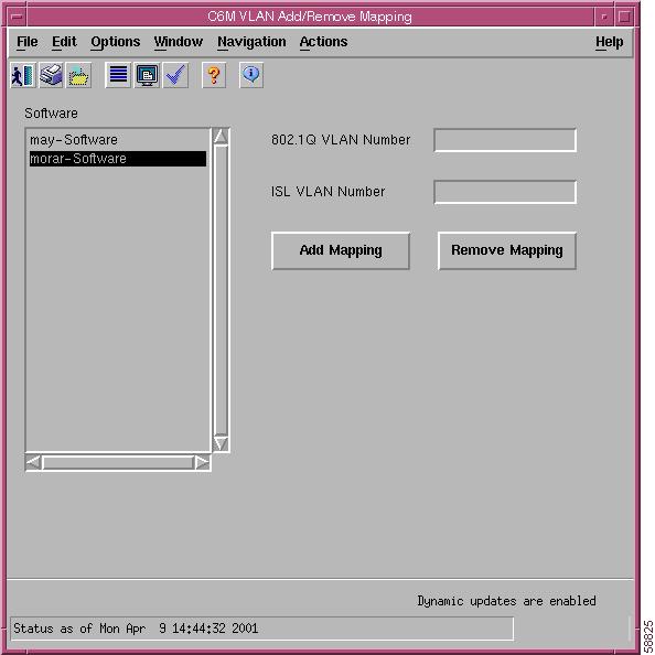
802.1Q Trunk Remapped VLANs Area
This area lists the mappings between 802.1Q and ISL VLANs. The information in this area is common to all VLAN objects for a particular switch or router:
•
–
–
•
Note
Enter the 802.1Q VLAN and ISL VLAN numbers for which a mapping is to be added or removed.
Note
Figure 6-37 Add/Remove VLAN Mapping Subdialog Box
•
•
•
•
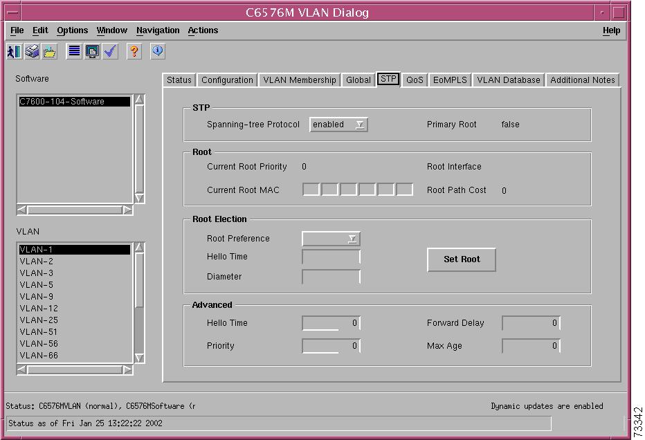
STP Tab
Figure 6-38 shows the VLAN STP tab of the C6576M VLAN dialog box.
Figure 6-38 VLAN STP Tab for the C6576M VLAN Dialog Box
STP Area
The STP area of the C6576M VLAN dialog provides the following information:
•
–
–
–
•
Root Area
The Root area of the C6576M VLAN dialog provides the following information:
•
•
•
•
Root Election Area
The Root Election area of the C6576M VLAN dialog provides the following information:
•
–
–
–
•
•
•
Advanced Area
The Advanced area of the C6576M VLAN dialog box allows you to configure the attributes described in this section. While these attributes are configurable, this is not the recommended method for configuring them. Alternately, if you specify a network diameter but no hello time, forward-delay timer, or max-age timer, using the Set Root button (in the Root Election Area) causes the switch to automatically calculate the optimal hello time, forward-delay timer, and max-age timer for that diameter.
•
•
•
•
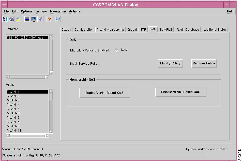
QoS Tab
Figure 6-39 shows the QoS tab of the C6576M VLAN dialog box.
Figure 6-39 QoS Tab of the VLAN Dialog Box
QoS Area
The QoS area allows you to enable or disable Microflow policing of bridged traffic on the VLAN, and attach or detach service policies to VLAN interfaces.
Note
•
•
•
Note
•
Membership QoS Area
The Membership QoS area allows you to enable or disable VLAN-based QoS on the VLAN's member interfaces.
•
•
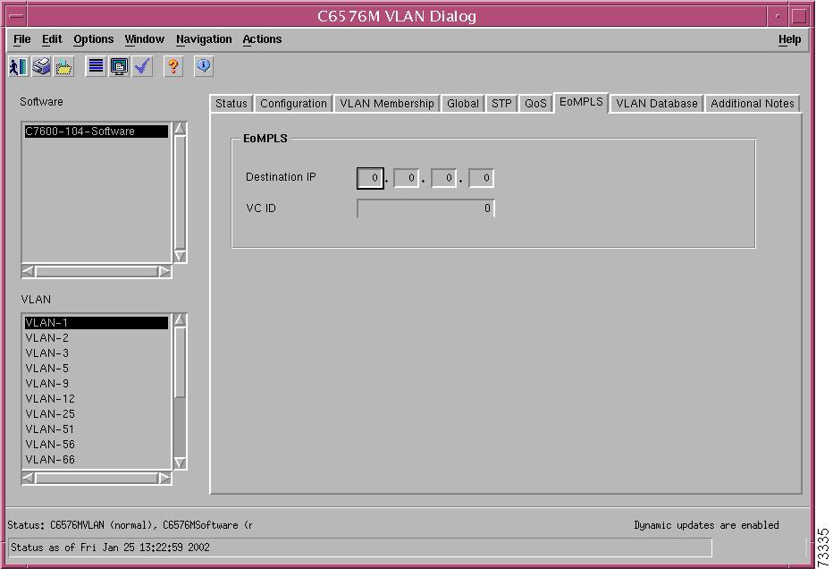
EoMPLS Tab
Figure 6-40 shows the EoMPLS tab of the C6576M VLAN dialog box.
Figure 6-40 EoMPLS Tab of the C6576M VLAN Dialog Box
EoMPLS Area
This area contains the followng information:
•
•
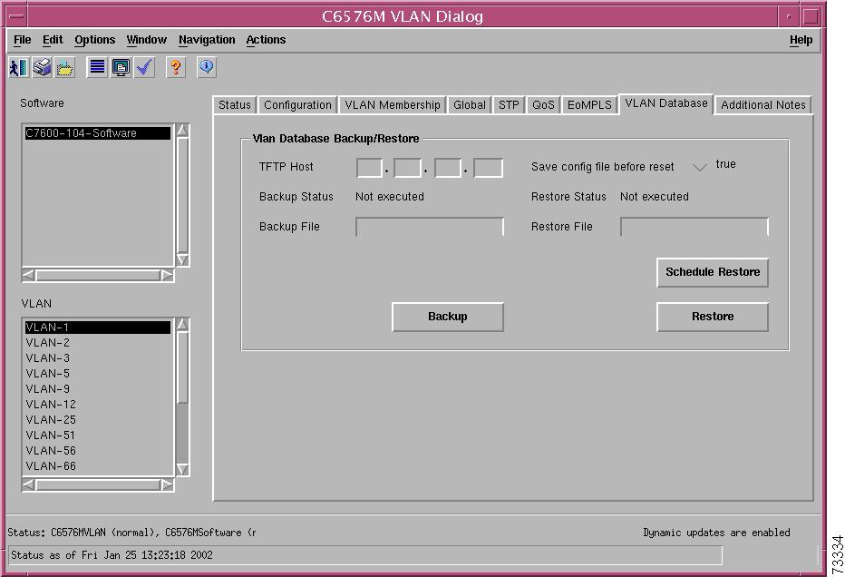
VLAN Database Tab
Figure 6-41 shows the VLAN Database tab of the C6576M VLAN dialog box. There is no VLAN Database in Hybrid OS.
Figure 6-41 VLAN Database Tab of the C6576M VLAN Dialog Box
VLAN Database Backup/Restore Area
The VLAN Database Backup/Restore area of the C6576M VLAN dialog box allows you to back up and restore the VLAN configuration to a remote TFTP server.
•
•
–
–
–
•
•
•
–
–
–
•
•
•
Caution
•
Figure 6-42 Scheduled Restore VLAN Configuration Dialog Box
Note
Note
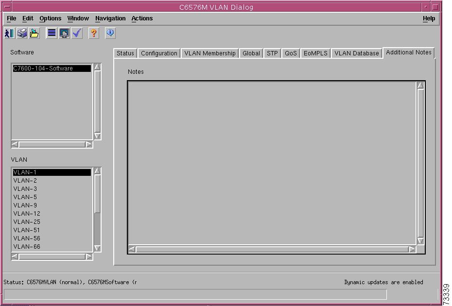
Additional Notes Tab
Figure 6-43 shows the Additional Notes tab of the C6576M VLAN dialog box.
Figure 6-43 Additional Notes Tab of the C6576M VLAN Dialog Box
Notes Area
The Notes area is a text box that allows you to type in additional notes for the object.
C6576M EtherChannel Dialog Box
This dialog box provides attributes for EtherChannel configurations. This dialog box can be launched from the Software object or EtherChannel objects in the Physical view.
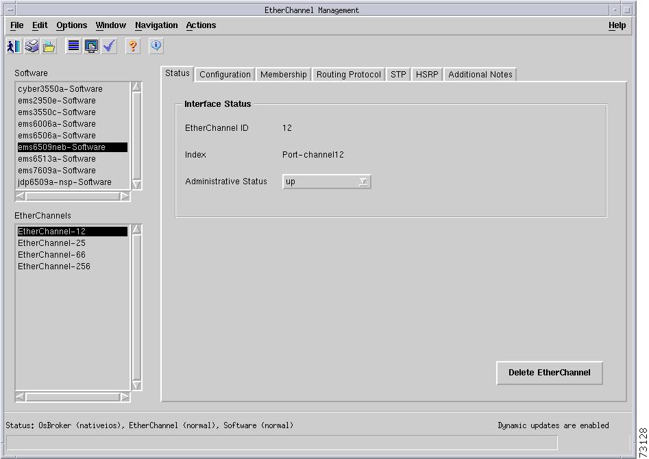
Status Tab
Figure 6-44 shows the Status tab of the C6576M EtherChannel dialog box.
Figure 6-44 Status Tab of the C6576M EtherChannel Dialog Box
Interface Status Area
The Details area of the C6576M EtherChannel dialog box provides the following information:
•
•
•
–
–
–
Note
Note
•
Status Field
The Status display-only field located at the bottom of the window indicates the current state of the object. This field has the following values:
•
•
•
Configuration Tab
Figure 6-45 shows the Configuration tab of the C6576M EtherChannel dialog box.
Figure 6-45 Configuration Tab of the C6576M EtherChannel Dialog Box
General Area
The General area provides the following information:
•
–
–
•
•
Note
•
Note
•
–
–
•
–
–
–
Layer 2 Area
The Layer 2 area contains the following information:
•
Layer 3 Area
The Layer 3 area contains the following information:
•
•
•
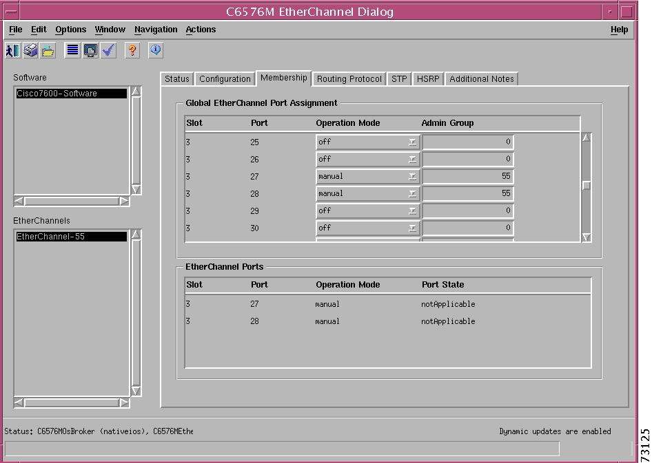
Membership Tab
Figure 6-46 shows the Membership tab of the C6576M EtherChannel dialog box.
Figure 6-46 Membership Tab of the C6576M EtherChannel Dialog Box
Global EtherChannel Ports Assignment Area
This area lists the EtherChannel assignments for all interfaces on the selected software (switch) instance and is not specific to any EtherChannel instance. In native IOS, this can be used to add ports to an EtherChannel instanceby setting the operational mode to "manual" or "auto" and specifying the channel number. If the specified channel number does not exist, it will be immediately created on the switch. In hybrid mode, this area assigns ports to channel admin groups, from which the switch will automatically form active EtherChannel instances. The table contains the following information:
•
•
•
–
–
•
Note
EtherChannel Ports Area
The EtherChannel Ports area lists the interfaces that belong to the selected EtherChannel:
•
•
•
–
–
–
–
•
–
–
–
–
–
–
–
–
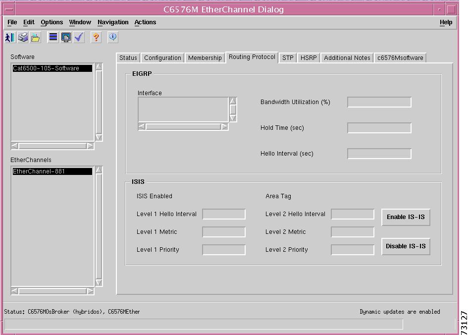
Routing Protocol Tab
Figure 6-47 shows the Routing Protocol tab of the C6576M EtherChannel dialog box.
Figure 6-47 Routing Protocol Tab of the C6576M EtherChannel Dialog Box
EIGRP Area
The EIGRP area of the C6576M EtherChannel dialog box provides the following information:
•
•
•
•
ISIS Area
The ISIS area of the C6576M EtherChannel dialog box provides the following information:
•
–
–
•
•
•
•
•
•
•
•
Note
•
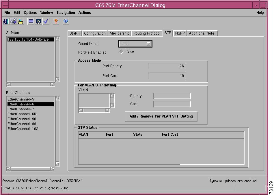
STP Tab
Figure 6-48 shows the STP tab of the C6576M EtherChannel dialog box.
Figure 6-48 STP Tab for the C6576M EtherChannel Dialog Box
The area at the top of the STP tab provides the following information:
•
–
–
•
–
–
Access Mode Area
The Access Mode area of the C6576M Ethernet Interface dialog box provides the following information:
•
–
–
–
–
•
Note
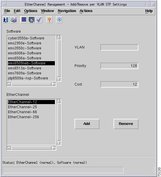
Per VLAN STP Setting Area
The Per VLAN STP Setting area in the STP tab of the C6576M Ethernet Interface dialog box provides the following information:
•
Note
•
–
–
–
–
•
Note
•
–
–
–
–
–
Figure 6-49 Add / Remove Per VLAN STP Setting Subdialog Box
STP Status Area
The STP Status area of the C6576M Ethernet Interface dialog box provides the following information:
•
–
–
–
–
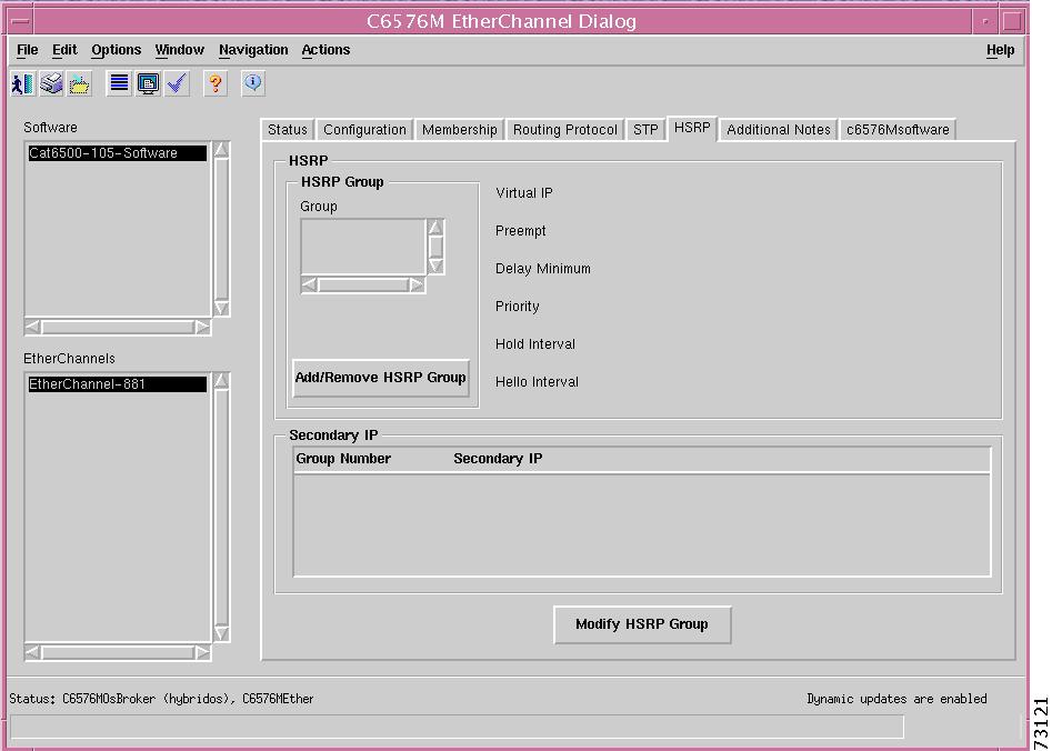
HSRP Tab
Figure 6-50 shows the HSRP tab of the C6576M EtherChannel dialog box.
Figure 6-50 HSRP Tab for the C6576M EtherChannel Dialog Box
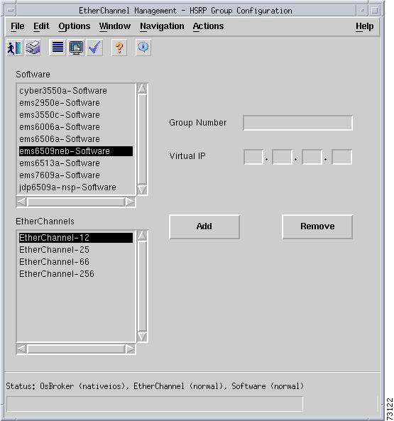
HSRP Area
The HSRP area of the C6576M Ethernet Interface dialog box provides the following information:
•
Note
•
•
–
–
•
•
•
•
•
Figure 6-51 HSRP Group Configure Subdialog Box
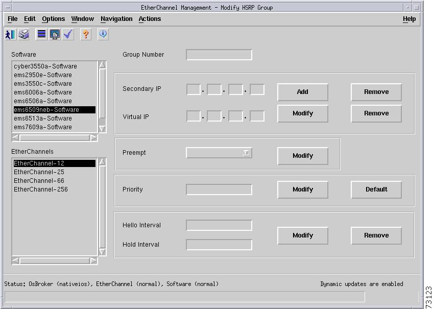
Secondary IP Area
The Secondary IP area of the C6576M Ethernet Interface dialog box provides the following information:
•
–
–
•
–
–
–
–
–
–
–
Figure 6-52 HSRP Secondary IP Modify Subdialog Box
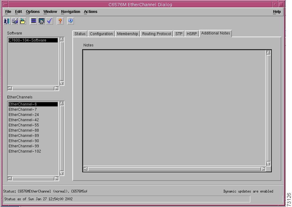
Additional Notes Tab
Figure 6-53 shows the Additional Notes tab of the C6576M EtherChannel dialog box.
Figure 6-53 Additional Notes Tab of the C6576M EtherChannel Dialog Box
Notes Area
The Notes area is a text box that allows you to type in additional notes for the object.
C6576M BGP Dialog Box
The C6576M BGP dialog box provides information for the IOS Border Gateway Protocol (BGP). This dialog box can be launched from the Software object or BGP object in the Physical view.
BGP Tab
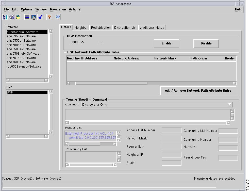
Figure 6-54 shows the BGP tab of the C6576M BGP dialog box.
Figure 6-54 BGP Tab of the C6576M BGP Dialog Box
BGP Information Area
The BGP Information area of the C6576M BGP dialog box provides the following information:
•
•
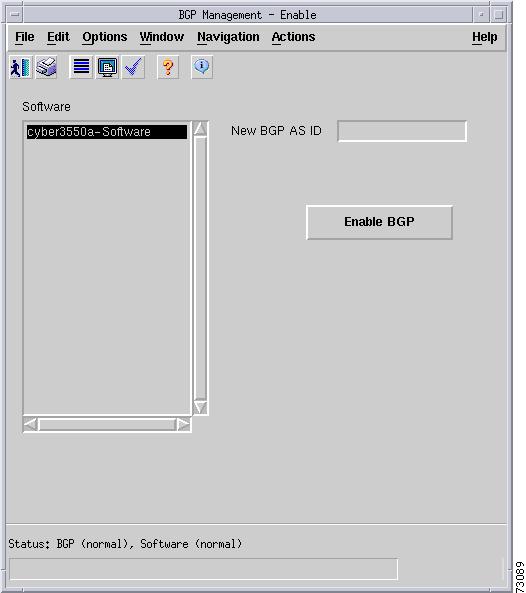
To enable BGP on the switch or router, specify the BGP autonomous system number and then click Enable BGP. An error will be reported if BGP is already enabled on the switch or router.
•
Figure 6-55 BGP Enable Dialog Box
BGP Network Path Attribute Table Area
The BGP Network Path Attribute Table area contains information about paths to destination networks received from all BGP peers. This area contains the following columns:
•
•
•
•
–
–
–
•
•
•
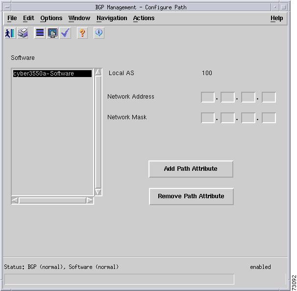
•
Specify the IP and network mask of the network to be added or removed from the BGP process.
Figure 6-56 Add or Remove BGP Path Attributes Dialog Box
Status Field
The Status display-only field located at the bottom of the window indicates the current state of the object. This field has the following values:
•
•
•
Neighbor Tab
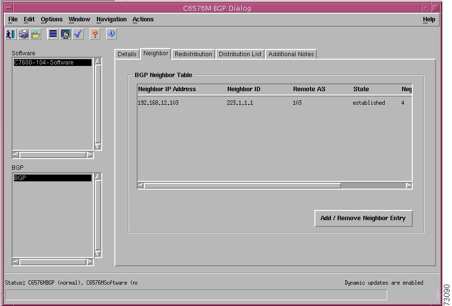
Figure 6-57 shows the Neighbor tab of the C6576M BGP dialog box.
Figure 6-57 Neighbor Tab of the C6576M BGP Dialog Box
BGP Neighbor Table Area
This area lists the BGP neighbors of the local BGP process:
•
•
•
•
–
–
–
–
–
–
•
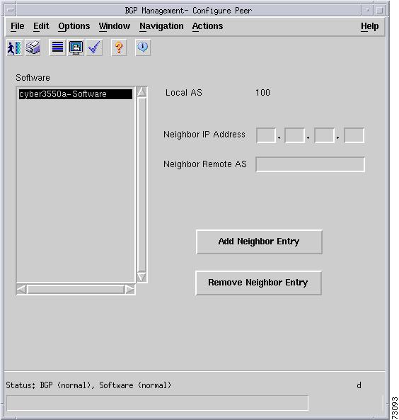
•
Specify the neighbor IP address and remote AS number to add or remove the neighbor from the local BGP neighbor table.
Figure 6-58 Add or Remove BGP Peers Dialog Box
Redistribution Tab
Figure 6-59 shows the Redistribution tab of the C6576M BGP dialog box.
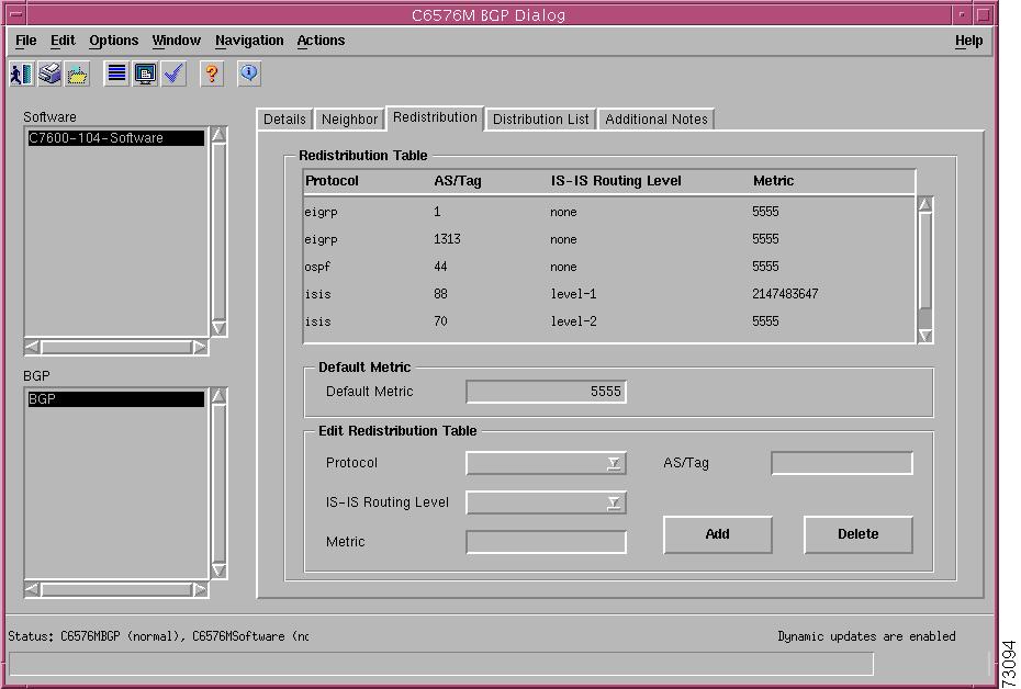
Figure 6-59 Redistribution Tab of the C6576M BGP Dialog Box
Redistribution Table Area
This area describes the route redistribution configuration of the BGP routing process. Routes learned from other interior and exterior routing protocols may be redistributed into the BGP routing domain.
•
–
–
–
•
•
–
–
–
–
•
Default Metric Area
This area has one attribute:
•
Edit Redistribution Table Area
This area allows changes to be made to the Redistribution Table:
•
•
•
–
–
–
•
•
•
Distribution List Tab
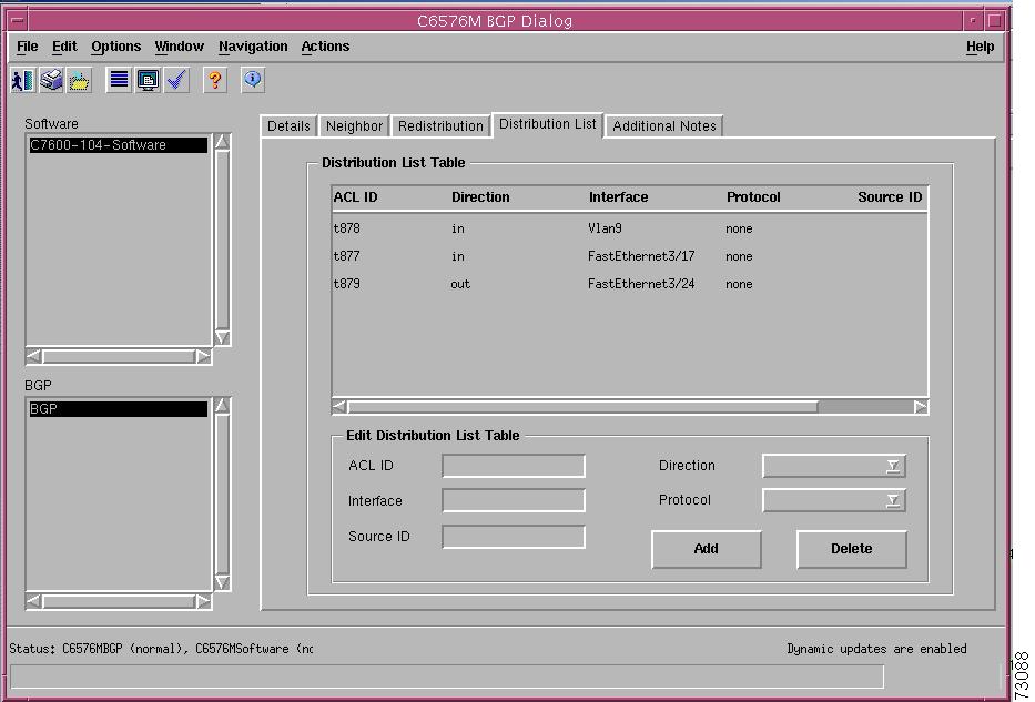
Figure 6-60 shows the Distribution List tab of the C6576M BGP dialog box.
Figure 6-60 Distribution List Tab of the C6576M BGP Dialog Box
Distribution List Table Area
This area describes filtering of routing updates sent or received by the routing process.
•
–
–
–
•
–
–
•
–
–
–
–
–
–
–
–
•
•
–
–
–
–
Edit Distribution Table Area
This area allows changes to be made to the Distribution Table attributes described in the "Distribution List Table Area" section:
•
•
•
•
•
•
•
Additional Notes Tab
Figure 6-61 shows the Additional Notes tab of the C6576M BGP dialog box.
Figure 6-61 Additional Notes Tab of the C6576M BGP Dialog Box
Notes Area
The Notes area is a text box that allows you to type in additional notes for the object.
C6576M OSPF Dialog Box
The C6576M OSPF dialog box provides information for all IOS Open Shortest Path First (OSPF) routing protocol processes. This dialog box can be launched from the Software object or OSPF objects in the Physical view.
Details Tab
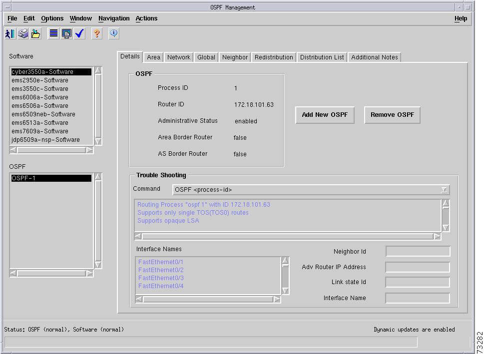
Figure 6-62 shows the Details tab of the C6576M OSPF dialog box.
Figure 6-62 Details Tab of the C6576M OSPF Dialog Box
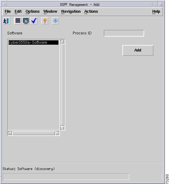
OSPF Area
The OSPF area of the C6576M OSPF dialog box describes the OSPF area configurations:
•
•
•
•
•
•
Note
Specify the OSPF Process ID (number only) and click Add to create the OSPF process on the switch or router. The string "OSPF-" will be prepended automatically to the process ID.
Note
•
Figure 6-63 Add OSPF Processes Dialog Box
Status Field
The Status display-only field located at the bottom of the window indicates the current state of the object. This field has the following values:
•
•
•
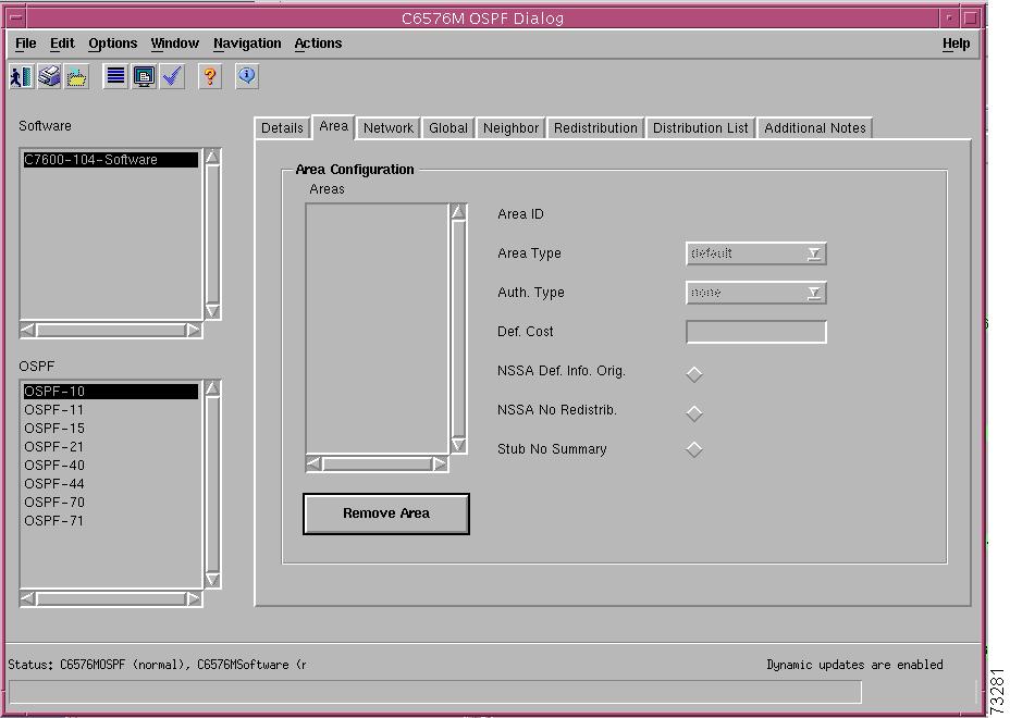
Area Tab
Figure 6-64 shows the Area tab of the C6576M OSPF dialog box.
Figure 6-64 Area Tab of the C6576M OSPF Dialog Box
Area Configuration Area
This describes OSPF NSSA and stub area configurations. The information for a particular area can be displayed by selecting the desired area from the Areas list. When you select an area, the following information is provided:
•
•
–
–
–
•
–
–
–
•
•
•
•
•
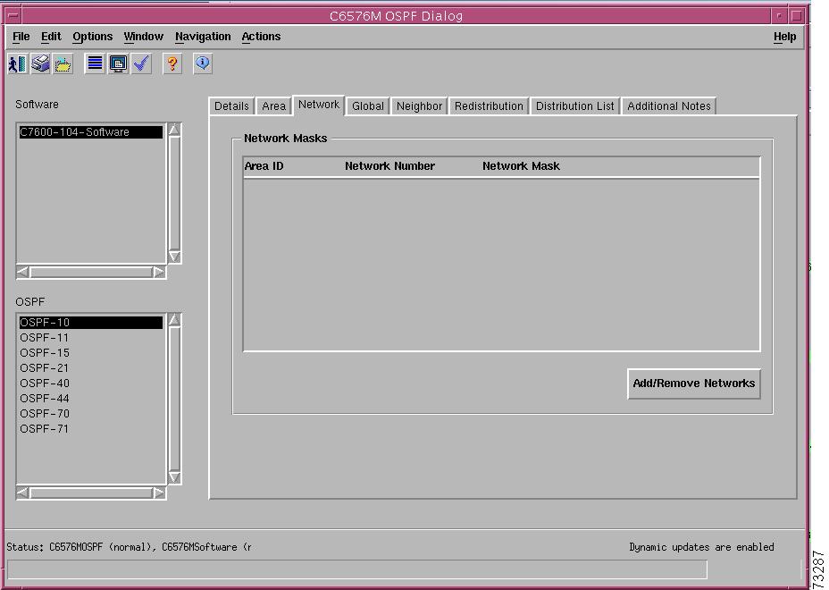
Network Tab
Figure 6-65 shows the Network tab of the C6576M OSPF dialog box.
Figure 6-65 Network Tab of the C6576M OSPF Dialog Box
Network Masks Area
The table in this area displays the networks associated with the selected OSPF process. This table contains the following information:
•
•
•
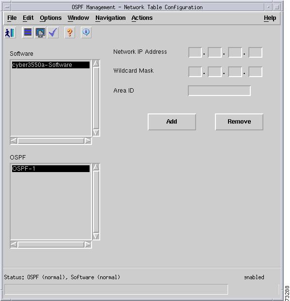
•
Specify the Network IP Address, Wildcard Mask, and the Area ID to be added or removed from the OSPF process.
Figure 6-66 Add or Remove OSPF Networks Dialog Box
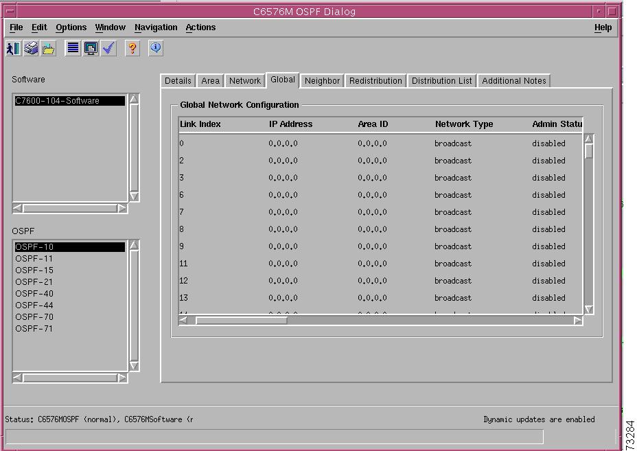
Global Tab
Figure 6-67 shows the Global tab of the C6576M OSPF dialog box.
Figure 6-67 Global Tab of the C6576M OSPF Dialog Box
Global Network Configuration Table
This describes the OSPF view of all interfaces on the router. This table contains the following columns:
•
•
•
•
–
–
–
–
•
–
–
•
•
•
•
•
•
•
•
•
•
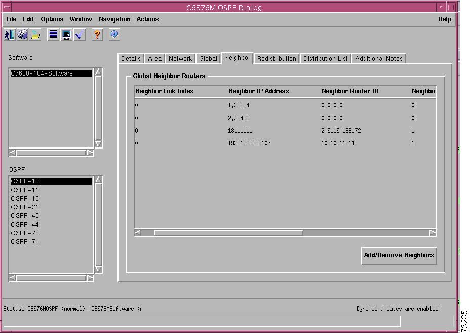
Neighbor Tab
Figure 6-68 shows the Neighbor tab for the C6576M OSPF dialog box.
Figure 6-68 Neighbor Tab of the C6576M OSPF Dialog Box
Global Neighbor Routers Area
This area lists all OSPF neighbors for all OSPF processes. This area consists of the following columns:
•
•
•
•
•
–
–
–
–
–
–
–
–
•
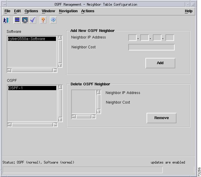
•
When adding a new neighbor, specify the neighbor router's IP address and the cost associated for this neighbor, and click the Add button.
To remove a neighbor, choose the neighbor in the Neighbor Table and click the Remove button. The Neighbor IP Address and Cost are displayed for the neighbor selected.
Figure 6-69 Add or Remove OSPF Neighbors Dialog Box
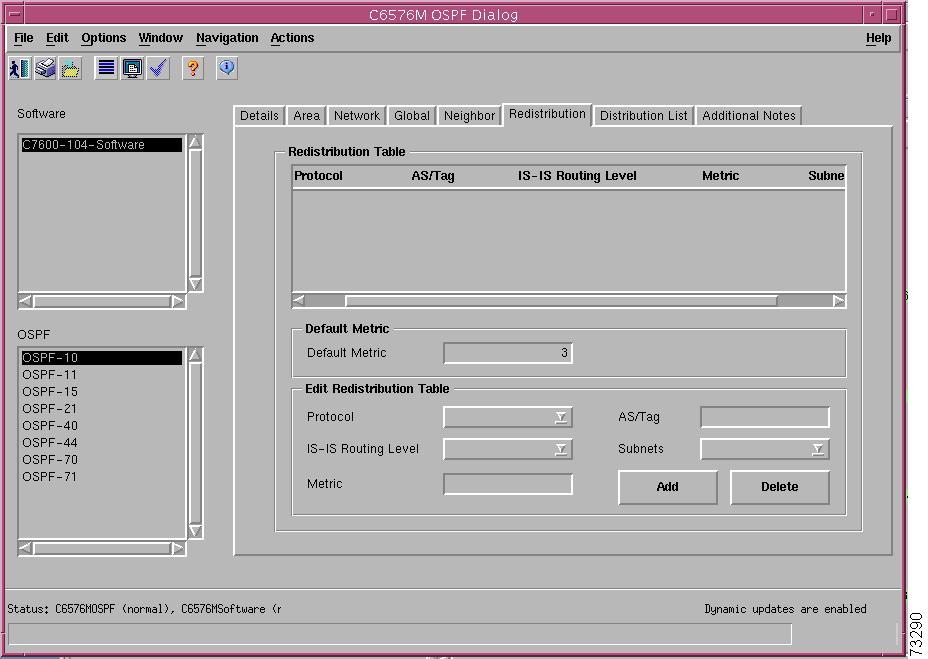
Redistribution Tab
Figure 6-70 shows the Redistribution tab of the C6576M OSPF dialog box.
Figure 6-70 Redistribution Tab of the C6576M OSPF Dialog Box
Redistribution Table Area
This area describes the route redistribution configuration of the OSPF routing process. Routes learned from other interior and exterior routing protocols may be redistributed into the OSPF routing domain.
•
–
–
–
–
•
•
–
–
–
–
•
•
Default Metric Area
•
Edit Redistribution Table Area
This area allows changes to be made to the attributes in the Redistribution Table. These attributes are discussed in detail in the "Redistribution Table Area" section.
•
•
•
•
•
•
•
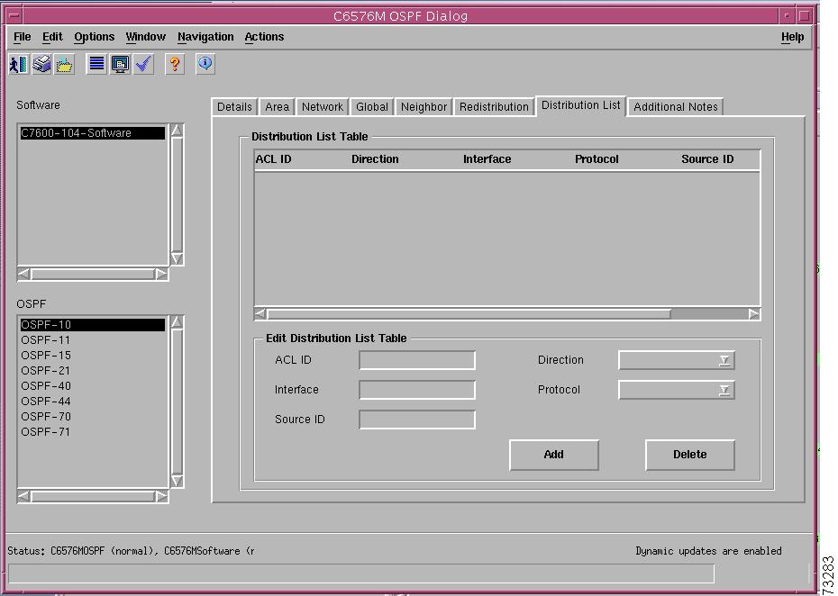
Distribution List Tab
Figure 6-71 shows the Distribution List tab of the C6576M OSPF dialog box.
Figure 6-71 Distribution List Tab of the C6576M OSPF Dialog Box
Distribution List Table Area
This area describes filtering of routing updates sent or received by the routing process.
•
–
–
–
•
–
–
•
–
–
–
–
–
–
–
–
•
•
Edit Distribution Table Area
This area allows changes to be made to the Distribution Table:
•
•
•
•
•
•
•
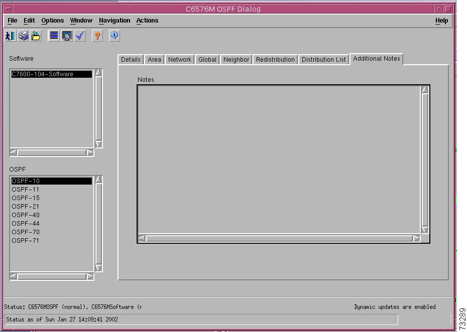
Additional Notes Tab
Figure 6-72 shows the Additional Notes tab of the C6576M OSPF dialog box.
Figure 6-72 Additional Notes Tab of the C6576M OSPF Dialog Box
Notes Area
The Notes area is a text box that allows you to type in additional notes for the object.
C6576M EIGRP Dialog Box
The C6576M EIGRP dialog box provides information on the Enhanced Interior Gateway Routing Protocol (EIGRP) enabled in IOS. This dialog box is launched from the Software object or EIGRP objects in the Physical view.
Note
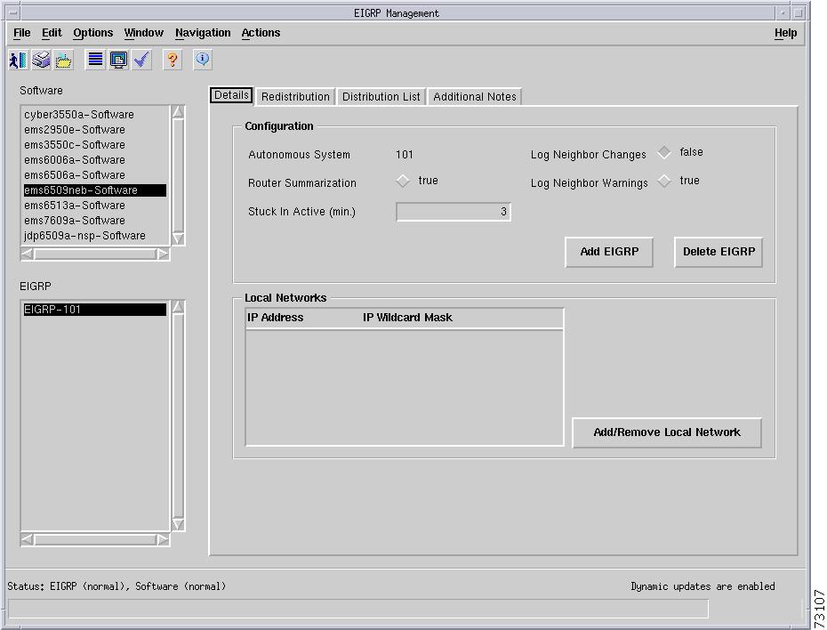
Details Tab
Figure 6-73 shows the Details tab of the C6576M EIGRP dialog box.
Figure 6-73 Details Tab of C6576M EIGRP Dialog Box
Configuration Area
The Configuration area of the C6576M EIGRP dialog box provides the following information:
•
•
•
•
•
•
•
–
–
–
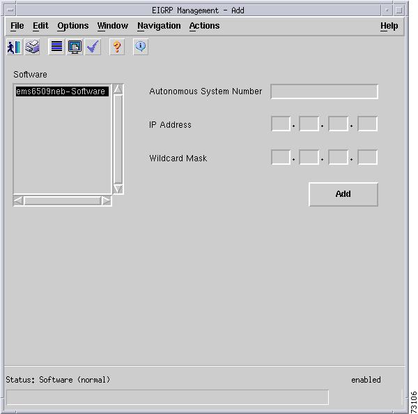
Figure 6-74 Add EIGRP Processes Dialog Box
Note
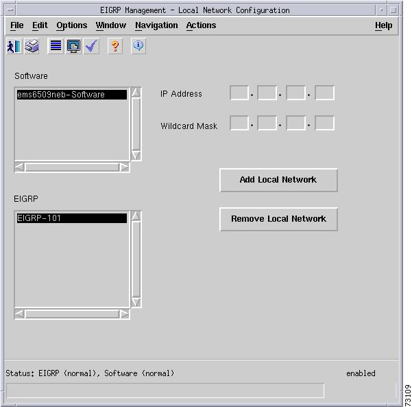
Local Networks Area
This area describes the networks supported by EIGRP. EIGRP will send routing updates on the interfaces in the networks. If the network of an interface is not specified, it will not be advertised by EIGRP. This area consists of the following columns:
•
•
•
Specify the IP address and IP mask of the entry to be added or removed from the local network table.
Figure 6-75 Add or Remove Networks to the EIGRP Process Dialog Box
Status Field
The Status display-only field located at the bottom of the window indicates the current state of the object. This field has the following values:
•
•
•
Redistribution Tab
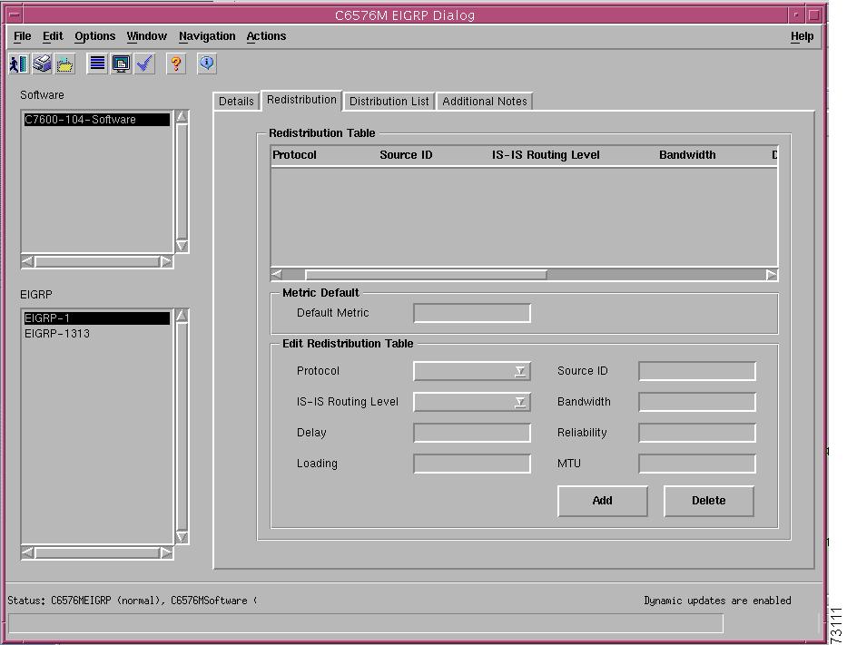
Figure 6-76 shows the Redistribution tab of the C6576M EIGRP dialog box.
Figure 6-76 Redistribution Tab of the C6576M EIGRP Dialog Box
Redistribution Table Area
This area describes the route redistribution configuration of the EIGRP routing process. Routes learned from other interior and exterior routing protocols may be redistributed into the EIGRP routing domain.
•
–
–
–
–
–
•
–
–
–
–
•
–
–
–
–
•
•
•
•
•
Metric Default Area
•
Edit Redistribution Table Area
This area allows changes to be made to the attributes shown in the Redistribution Table. These attributes are discussed in detail in the "Redistribution Table Area" section.
•
–
–
–
–
–
•
•
•
•
•
•
•
•
•
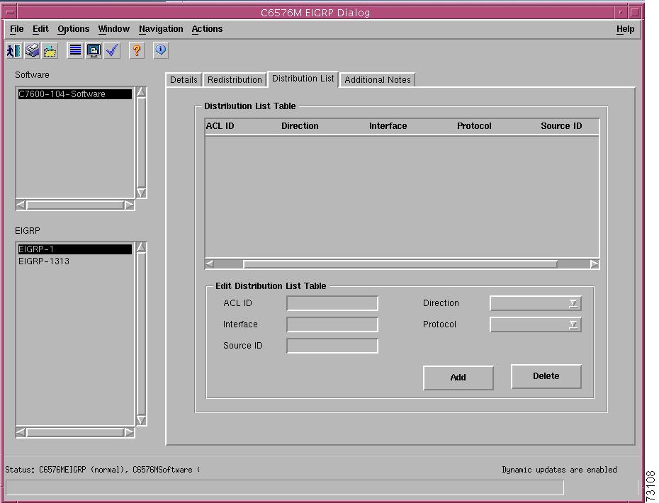
Distribution List Tab
Figure 6-77 shows the Distribution List tab of the C6576M EIGRP dialog box.
Figure 6-77 Distribution List Tab of the C6576M EIGRP Dialog Box
Distribution List Table Area
This area describes filtering of routing updates sent or received by the routing process.
•
–
–
–
•
–
–
•
–
–
–
–
–
–
–
–
•
–
–
–
–
–
•
Edit Distribution List Table Area
This area allows changes to be made to the Distribution Table:
•
•
•
–
–
–
–
•
•
•
•
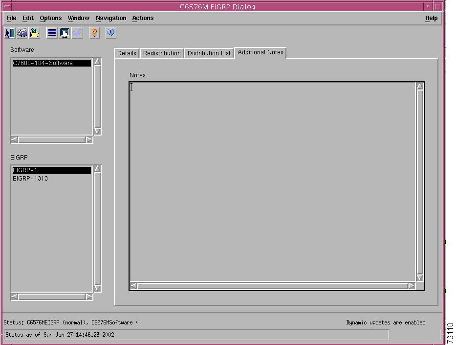
Additional Notes Tab
Figure 6-78 shows the Additional Notes tab of the C6576M EIGRP dialog box.
Figure 6-78 Additional Notes Tab of the C6576M EIGRP Dialog Box
Notes Area
The Notes area is a text box that allows you to type in additional notes for the object.
C6576M IS-IS Dialog Box
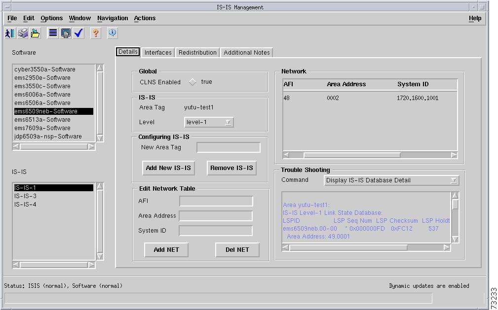
The C6576M IS-IS dialog box provides information on the OSI Intermediate System to Intermediate System (IS-IS) routing process on a Catalyst 6000/6500 series switch or Cisco 7600 series Internet Router. This dialog box is launched from the Software object or IS-IS objects in the Physical view.
Details Tab
Figure 6-79 shows the Details tab of the C6576M IS-IS dialog box.
Figure 6-79 Details Tab of C6576M IS-IS Dialog Box
Global Area
The Global area of the C6576M IS-IS dialog box provides the following information:
•
IS-IS Area
The IS-IS area of the C6576M IS-IS dialog box provides the following information:
•
•
Note
Configuring IS-IS Area
The Configuring IS-IS area allows you to create an IS-IS routing process on the managed device and deploy an instance of the IS-IS object in the element manager.
•
•
•
Network Area
The Network area of the C6576M IS-IS dialog box provides the following information:
•
–
–
–
–
Edit Network Table Subarea
This subarea allows you to modify the Network Table. The Add and Remove buttons adds a NET address and removes a NET address from the IS-IS routing process, respectively. The following parameters must be specified.
•
•
•
Status Field
The Status display-only field located at the bottom of the window indicates the current state of the object. This field has the following values:
•
•
•
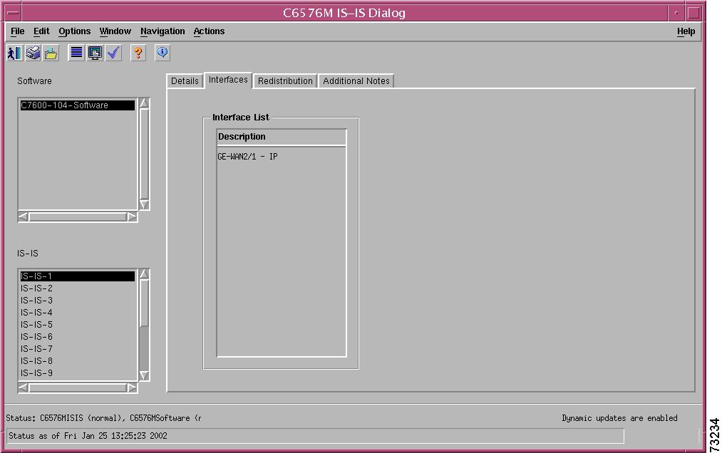
Interfaces Tab
Figure 6-80 shows the Interfaces tab of the C6576M IS-IS dialog box.
Figure 6-80 Interfaces Tab of C6576M IS-IS Dialog Box
Interface List Area
The Interface List area of the C6576M IS-IS dialog box lists the interfaces supported by a given IS-IS routing process. This table will be empty if CLNS routing is not enabled on the managed device. The table contains one column:
•
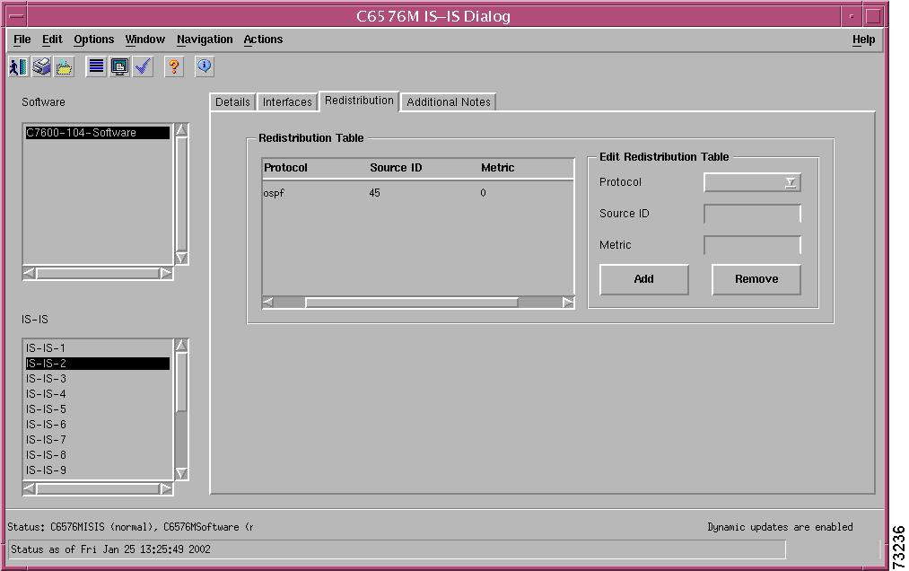
Redistribution Tab
Figure 6-81 shows the Interfaces tab of the C6576M IS-IS dialog box.
Figure 6-81 Redistribution Tab of C6576M IS-IS Dialog Box
Redistribution Table Area
The Redistribution Table area of the C6576M IS-IS dialog box describes the route redistribution configuration of an IS-IS routing process.
•
•
–
–
–
•
Edit Redistribution Table Area
The Edit Redistribution Table area of the C6576M IS-IS dialog box allows you to enable or disable route redistribution from another IP routing process into the IS-IS area. The following parameters must be given:
•
•
•
The Add and Remove buttons enable and disable route redistribution from another IP routing process into the IS-IS area, respectively.
Note
Additional Notes Tab
Figure 6-82 shows the Additional Notes tab of the C6576M IS-IS dialog box.
Figure 6-82 Additional Notes Tab of the C6576M IS-IS Dialog Box
Notes Area
The Notes area is a text box that allows you to type in additional notes for the object
C6576M NDE Configuration Dialog Box
The C6576M NDE Configuration dialog box provides information on the Netflow Data Export (NDE) configuration on a Catalyst 6000 family switch or a Cisco 7600 series Internet Router. There is only one instance of this class per managed device.
NDE makes traffic statistics available for analysis by an external data collector. You can use NDE to monitor all Layer 3 switched and all routed IP unicast traffic.
This dialog box is launched from the Software object or the NDE object in the physical view.
Details Tab
Figure 6-83 shows the Details tab of the C6576M NDE dialog box. The following attributes are shown in this tab:
•
•
Figure 6-83 Details Tab of C6576M NDE Dialog Box
PFC Area
The PFC area of the C6576M NDE dialog box provides the following information:
•
•
•
•
•
•
MSFC Area
The MSFC area of the C6576M NDE dialog box provides the following information:
•
•
•
•
•
Configuration Area
The Configuration area of the C6576M NDE dialog box allows you to modify the following attributes:
•
•
•
•
•
The configuration attributes are modified by clicking the following buttons:
•
•
•
•
Note
•
Status Field
The Status display-only field located at the bottom of the window indicates the current state of the object. This field has the following values:
•
•
•
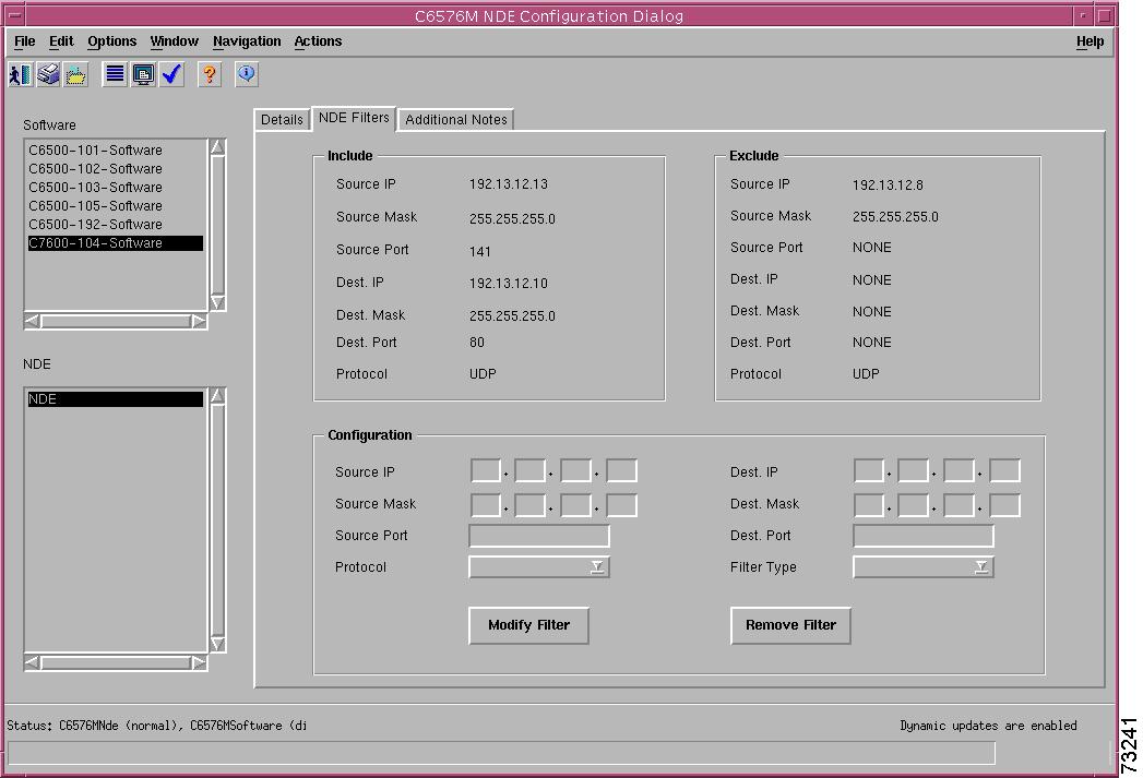
NDE Filters Tab
Figure 6-84 shows the NDE Filters tab of the C6576M NDE Configuration dialog box.
Figure 6-84 NDE Filters Tab of C6576M NDE Configuration Dialog Box
Include Area
This area allows you to specify include parameters for the NDE flow filters. This area consists of the following parameters:
•
•
•
•
•
•
•
Exclude Area
This area allows you to specify exclude parameters for the NDE flow filters. This area consists of the following parameters:
•
•
•
•
•
•
•
Configuration Area
This area allows you to modify all the parameters for the NDE flow filter, or to remove the filter.
•
•
•
•
•
•
•
–
–
•
–
–
–
The following buttons implement the configuation changes:
•
•
Additional Notes Tab
Figure 6-85 shows the Additional Notes tab of the C6576M NDE Configuration dialog box.
Figure 6-85 Additional Notes Tab of the C6576M NDE Configuration Dialog Box
Notes Area
The Notes area is a text box that allows you to type in additional notes for the object
C6576M STP Dialog Box
The C6576M STP dialog box provides information on the global Spanning Tree Protocol configuration on a managed Catalyst 6000 family switch or Cisco 7600 series Internet Router. This dialog box is launched from the Software object or STP object in the Physical view.
Details Tab
Figure 6-86 shows the Details tab of the C6576M STP dialog box.
Figure 6-86 Details Tab of C6576M STP Dialog Box
Details Area
The Details area of the C6576M STP dialog box provides the following information:
•
•
•
•
–
–
•
•
Status Field
The Status display-only field located at the bottom of the window indicates the current state of the object. This field has the following values:
•
•
•
Additional Notes Tab
Figure 6-87 shows the Additional Notes tab of the C6576M STP dialog box.
Figure 6-87 Additional Notes Tab of the C6576M STP Dialog Box
Notes Area
The Notes area is a text box that allows you to type in additional notes for the object.
C6576M ACL Configuration Dialog Box
The C6576M ACL dialog box describes a numbered or named access control list (ACL) on a Catalyst 6000/6500 series switch or Cisco 7600 series Internet Router. The C65/76M Controller supports standard and extended, named or numbered ACLs.
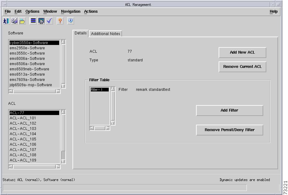
Details Tab
Figure 6-88 shows the Details tab of the C6576M ACL dialog box.
Figure 6-88 Details Tab of C6576M ACL Dialog Box
The Details tab of the C6576M ACL dialog box displays the following:
•
•
•
•
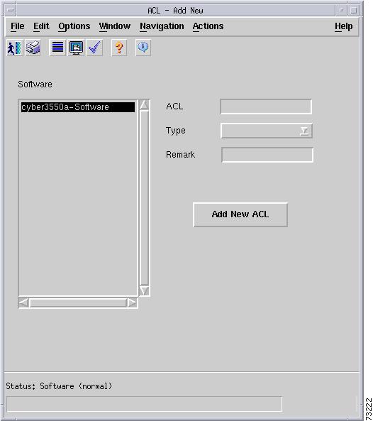
The ACL instance will be deployed with the object name "ACL-<id>". The following fields are displayed in the ACL Add subdialog box:
•
•
•
Figure 6-89 ACL Add Dialog Box
Filter Table Area
The Filter Table area of the C6576M ACL dialog box describes permit/deny filters or remark entries of an ACL. The order of entries in the list is relevant; filters are applied in the order they appear in the list.
Note
The list of filters is shown in the text box. Selecting one of the entries in the text box displays a description of the filter to the right of the box.
•
•
•
Filters can be configured using the following buttons:
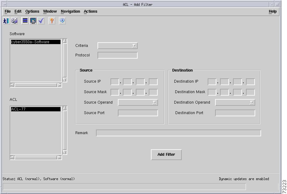
•
•
Figure 6-90 Add Filter Dialog Box
The following fields are displayed in this Add Filter subdialog box:
•
–
–
•
•
•
•
–
–
–
–
–
–
•
•
•
•
•
•
•
Status Field
The Status display-only field located at the bottom of the window indicates the current state of the object. This field has the following values:
•
•
•
Additional Notes Tab
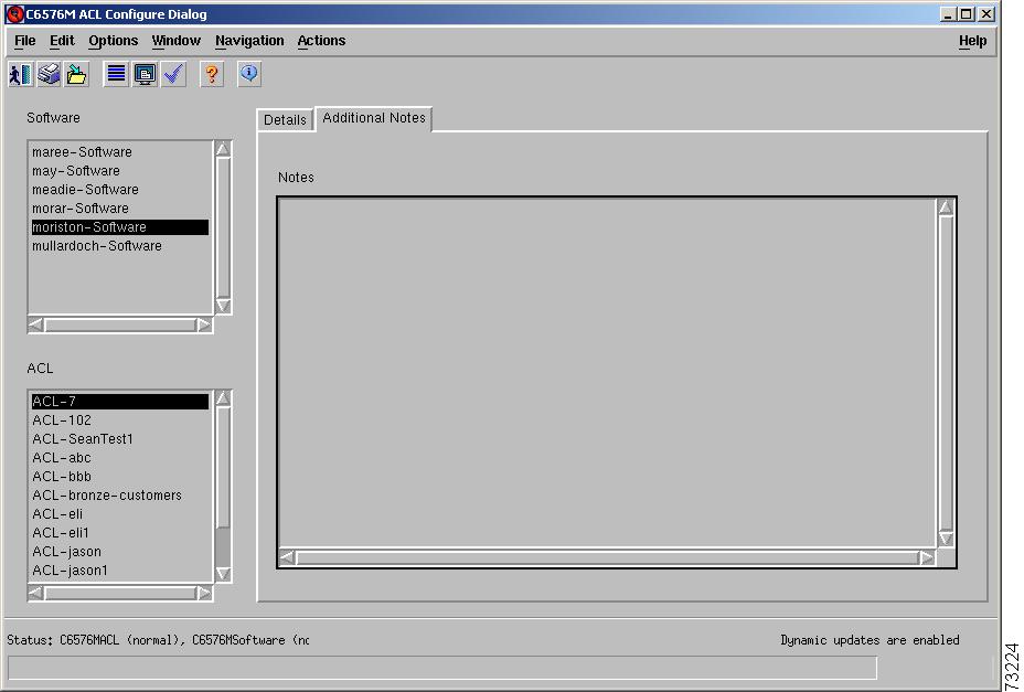
Figure 6-91 shows the Additional Notes tab of the C6576M ACL dialog box.
Figure 6-91 Additional Notes Tab of the C6576M ACL Configure Dialog Box
Notes Area
The Notes area is a text box that allows you to type in additional notes for the object
C6576M Loopback Dialog Box
The C6576M Loopback dialog box describes the deployment of all loopback interfaces on a Catalyst 6000/6500 series or Cisco 7600 series Internet Router. This dialog box is launched from the Software object or Loopback object in the Physical view.
Configuration Tab
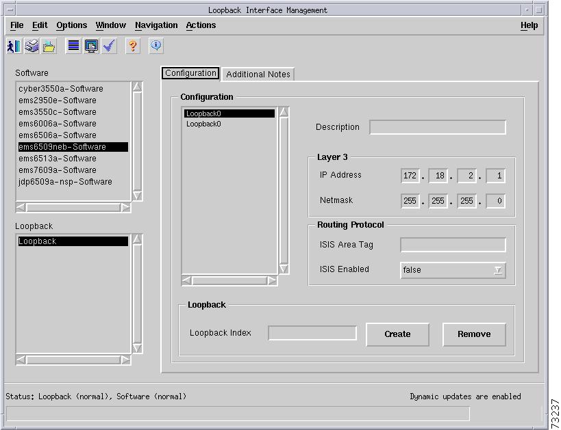
Figure 6-92 shows the Configuration tab of the C6576M Loopback dialog box.
Figure 6-92 Configuration Tab of C6576M Loopback Dialog Box
Loopback Area
The Loopback area of the C6576M Loopback dialog box provides the following information:
•
–
•
Layer 3 Subarea
•
•
Routing Protocol Subarea
•
•
Create Loopback Subarea
•
•
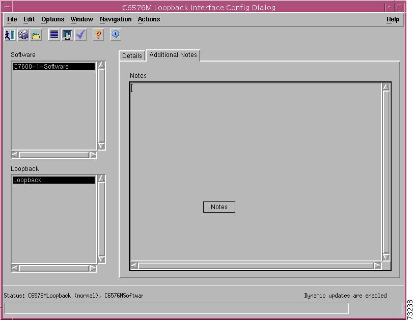
Additional Notes Tab
Figure 6-93 shows the Additional Notes tab of the C6576M Loopback dialog box.
Figure 6-93 Additional Notes Tab of the C6576M Loopback Dialog Box
Notes Area
The Notes area is a text box that allows you to type in additional notes for the object.
C6576M QoS Dialog Box
The C6576M QoS dialog box describes the global quality of service (QoS) engine process on a Catalyst 6000/6500 series or Cisco 7600 series Internet Router. This dialog box is launched from the Software object or QoS objects in the Physical view.
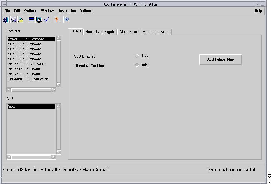
Details Tab
Figure 6-94 shows the Details tab of the C6576M QoS dialog box.
Figure 6-94 Details Tab of C6576M QoS Dialog Box
Details Area
The Details area of the C6576M QoS dialog box provides the following information:
•
–
–
•
–
–
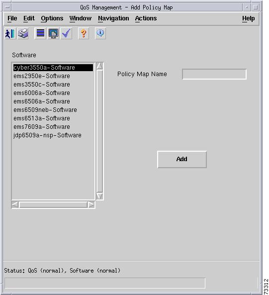
•
–
–
Figure 6-95 Add Policy Map Subdialog Box of the C6576M QoS Dialog Box
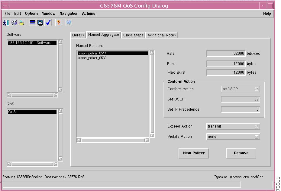
Named Aggregate Tab
Figure 6-96 shows the Named Aggregate tab of the C6576M QoS dialog box.
Figure 6-96 Named Aggregate Tab of C6576M QoS Dialog Box
Named Aggregate Area
The Named Aggregate area of the C6576M QoS dialog box describes the named aggregate policers defined globally on the device. This tab (not supported in Hybrid OS) contains the following information attributes:
•
–
•
•
•
Note
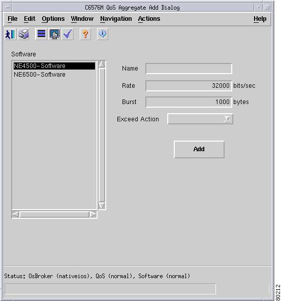
Conform Action Area
The Conform Action area of the C6576M QoS dialog box describes the named aggregate policers defined globally on the device. This tab contains the following information:
•
–
–
–
–
–
•
•
•
–
–
–
–
•
–
–
–
–
Note
•
Figure 6-97 QoS Aggregate Add Subdialog Box of the C6576M QoS Dialog Box
•
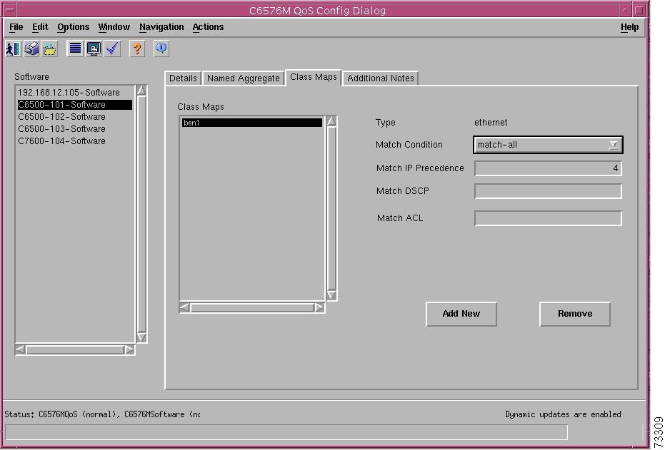
Class Maps Tab
Figure 6-98 shows the Class Maps tab of the C6576M QoS dialog box.
Figure 6-98 Class Maps Tab of C6576M QoS Dialog Box
Class Maps Area
The Class Maps area of the C6576M QoS dialog box describes globally defined class maps on the device. Class maps identify a selected stream of IP traffic based on a defined set of matching criteria. This tab contains the following information:
•
–
•
–
–
–
•
•
•
•
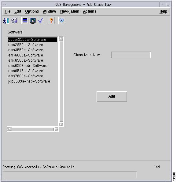
•
–
–
Figure 6-99 Add Class Map Subdialog Box of the C6576M QoS Dialog Box
•
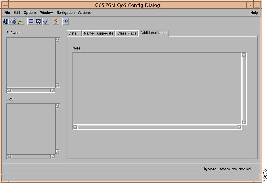
Additional Notes Tab
Figure 6-100 shows the Additional Notes tab of the C6576M QoS dialog box.
Figure 6-100 Additional Notes Tab of the C6576M QoS Dialog Box
Notes Area
The Notes area is a text box that allows you to type in additional notes for the object.
C6576M QoS Policy Map Dialog Box
The C6576M QoS Policy Map dialog box describes a quality of service (QoS) policy map on a Catalyst 6000/6500 series or Cisco 7600 series Internet Router. A policy map consists of one or more traffic filters defined by class maps. This dialog box is launched from the Software object or QoS Policy Map objects in the Physical view.
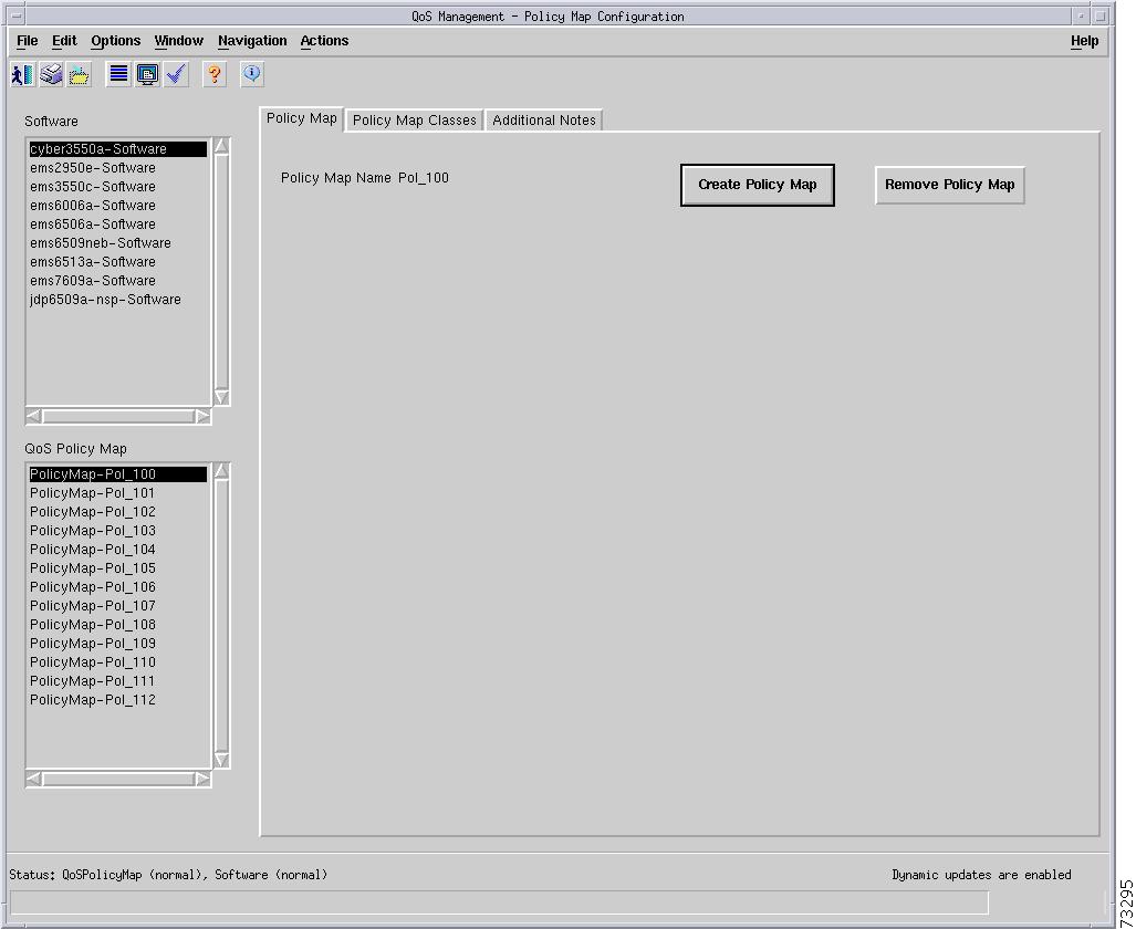
Policy Map Tab
Figure 6-101 shows the Policy Map tab of the C6576M QoS Policy Map dialog box.
Figure 6-101 Policy Map Tab of C6576M QoS Policy Map Dialog Box
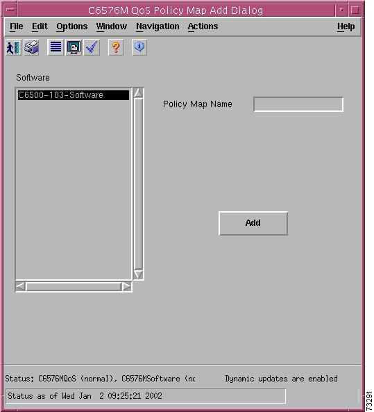
Policy Map Area
The Details area of the C6576M QoS Policy Map dialog box provides the following information:
•
•
–
–
•
Figure 6-102 Policy Map Add Subdialog Box of C6576M QoS Policy Map Dialog Box
Policy Map Classes Tab
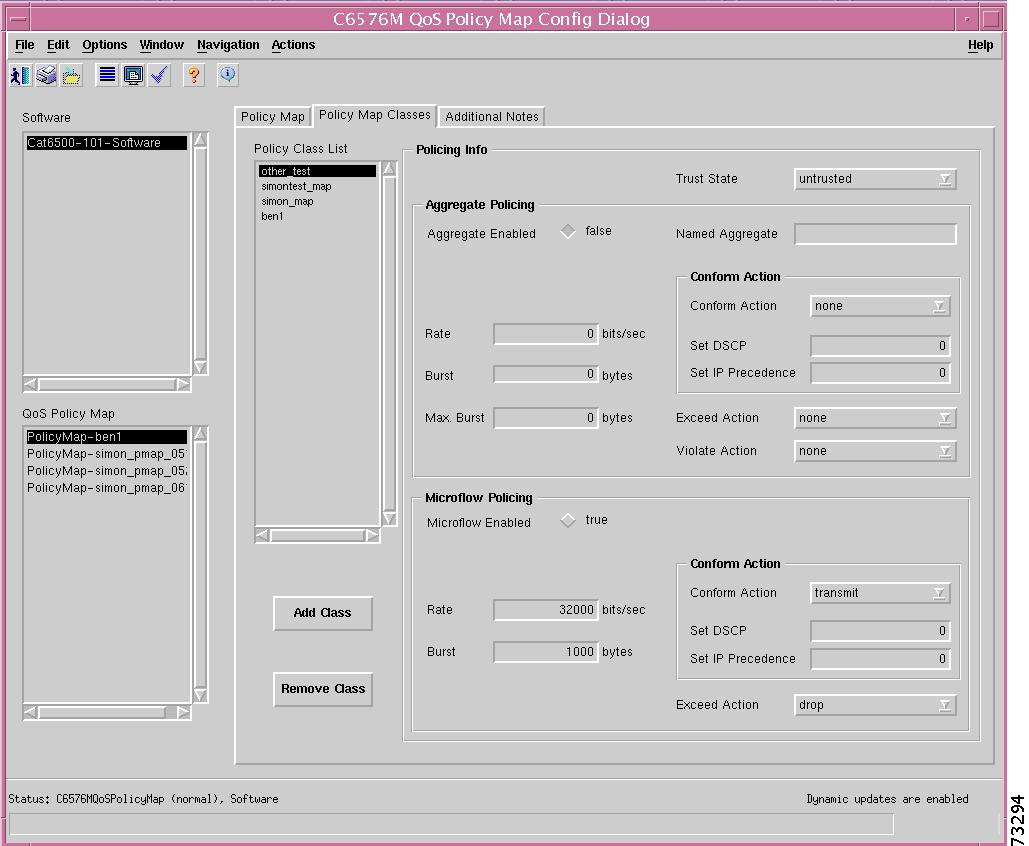
Figure 6-103 shows the Policy Map Classes tab of the C6576M QoS Policy Map dialog box.
Figure 6-103 Policy Map Classes Tab of C6576M QoS Policy Map Dialog Box
Policy Class List Area
The Policy Class List area of the C6576M QoS Policy Map dialog box provides the following information:
•
–
•
•
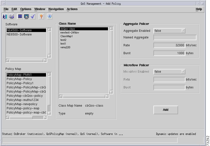
Figure 6-104 Policy Map Add Class Subdialog Box of C6576M QoS Policy Map Dialog Box
The following is shown in this subdialog box.
Class Name Area
•
•
•
–
–
–
Aggregate Policer
•
•
•
•
Microflow Policer
This is supported only in Native IOS.
•
–
–
•
•
•
Policing Info Area
The Policing Info area of the C6576M QoS Policy Map dialog box provides the following information:
•
–
–
–
–
Note
Aggregate Policing Subarea
•
•
•
•
•
Note
•
–
–
–
–
•
–
–
–
–
Note
Conform Action Subarea
•
–
–
–
–
–
•
•
Microflow Policing Subarea
This is supported in Native IOS only.
•
–
–
•
•
•
–
–
–
–
Conform Action Subarea
•
–
–
–
–
–
•
•
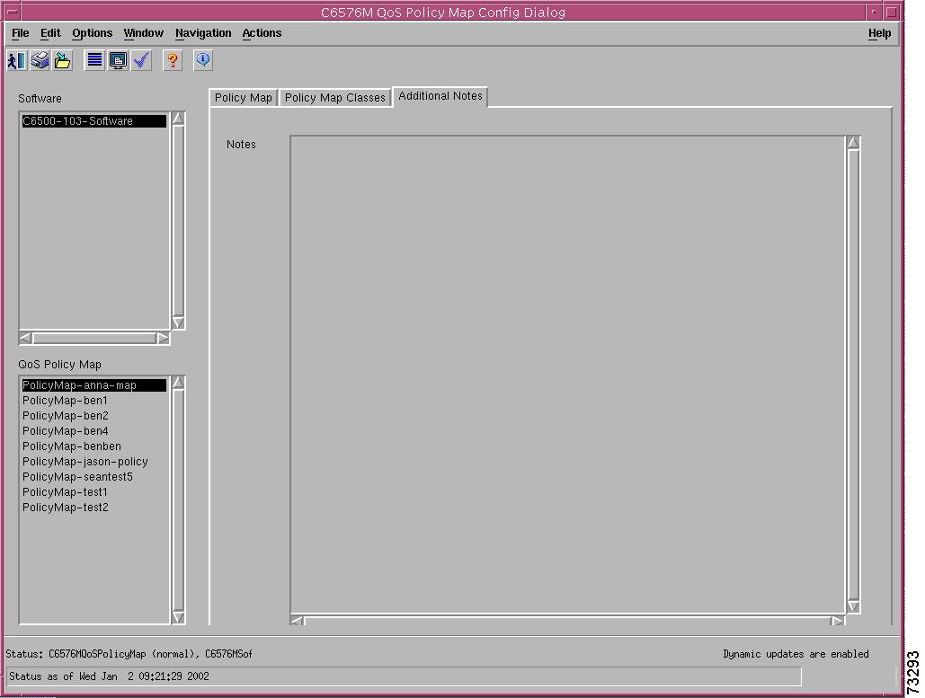
Additional Notes Tab
Figure 6-105 shows the Additional Notes tab of the C6576M QoS Policy Map dialog box.
Figure 6-105 Additional Notes Tab of the C6576M QoS Policy Map Dialog Box
Notes Area
The Notes area is a text box that allows you to type in additional notes for the object.