Feedback
Table Of Contents
C6576M Power Supply Dialog Box
C6576M Supervisor Module Dialog Box
System Flash Memory Inventory Area
C6576M Ethernet Module Dialog Box
C6576M Ethernet Interface Dialog Box
Packets/Octets Statistics Area
C6576M Switch Fabric Module Dialog Box
C6576M FlexWAN Module Dialog Box
C6576M Port Adapter Dialog Box
C6576M Optical Services Modules Dialog Box
C6576M ATM T3 Interface Dialog Box
Interface Packets/Octets Statistics Area
Interface Error Statistics Area
C6576M ATM E3 Interface Dialog Box
Interface Packets / Octets Statistics Area
Interface Error Statistics Area
C6576M ATM SONET Interface Dialog Box
SONET Medium Configuration Area
Interface Packets/Octets Statistics Area
Interface Error Statistics Area
SONET Section Error Statistics Area
SONET Line Error Statistics Area
SONET Far End Line Error Statistics Area
SONET Path Error Statistics Area
SONET Far End Path Error Statistics Area
C6576M OSM GE-WAN Interface Dialog Box
Packets/Octets Statistics Area
C6576M OSM Channelized SONET Interface Dialog Box
Interface Packets/ Octets Statistics Area
Interface Error Statistics Area
SONET Section Error Statistics Area
SONET Line Error Statistics Area
SONET Far End Line Error Statistics Area
C6576M OSM POS Interface Dialog Box
Packets/Octets Statistics Area
C6576M OSM Serial Subinterface Dialog Box
Interface Packets/Octets Statistics Area
Interface Error Statistics Area
C6576M OSM POS Subinterface Dialog Box
Interface Packets/Octets Statistics Area
Interface Error Statistics Area
Physical Object Dialog Boxes
This chapter describes the Cisco 6500/7600 Series Manager dialog boxes for the physical objects. The following physical object dialog boxes are available in the C65/76M:
•
C6576M Power Supply Dialog Box
•
•
•
•
•
•
•
•
•
•
•
•
•
•
•
Table 5-1 lists the pop-up menu launch points for all C65/76M dialog boxes.
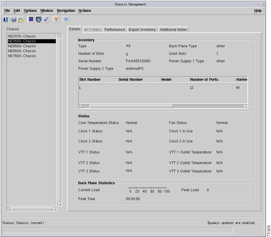
C6576M Chassis Dialog Box
This dialog box provides access to attributes for the physical chassis. This includes items such as the fan, temperature, and power supplies. This dialog box can be launched from a Network Element object or Chassis object within the Network or Physical containment views.
Only one Chassis object can be selected at a time from the Chassis object list on the left-hand side of the dialog box.
Status Tab
Figure 5-1 shows the Status tab of the C6576M Chassis dialog box.
Figure 5-1 Status Tab of the C6576M Chassis Dialog Box
General Area
The General area of the C6576M Chassis dialog box provides the following information:
•
–
–
–
Note
•
–
–
–
–
Note
Clock Area
The Clock area of the C6576M Chassis dialog box provides the following information:
•
–
–
•
–
–
VTT Area
The VTT area of the C6576M Chassis dialog box provides the following information:
•
–
–
•
–
–
–
Status Field
The Status display-only field located at the bottom of the window indicates the current state of the object. This field can have the following values:
•
•
•
•
•
•
•
Note
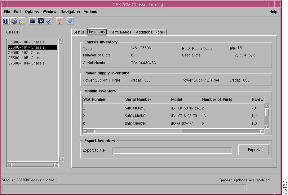
Inventory Tab
Figure 5-2 shows the Inventory tab of the C6576M Chassis dialog box.
Figure 5-2 Inventory Tab of the C6576M Chassis Dialog Box
Chassis Inventory Area
The Chassis Inventory area of the C6576M Chassis dialog box provides the following information:
•
–
–
–
–
–
–
–
–
–
•
•
•
•
Note
Power Supply Inventory Area
The Power Supply Inventory area of the C6576M Chassis dialog box provides the following information:
•
•
The possible types of power supplies are:
•
•
•
•
•
•
•
•
•
•
•
Module Inventory Area
The Module Inventory area of the C6576M Chassis dialog box provides a list of occupied slots, including the following information:
•
•
•
•
•
•
•
Export Inventory Area
The Export Inventory area can be used to export the information on this tab to a CSV file on the CEMF server host.
•
•
–
–
–
–
–
–
–
The following data is exported for each installed module in the chassis:
–
–
–
–
–
–
–
The inventory attributes are written in sections. Each section contains the attributes applicable to a particular class of object in the Cisco6500Manager containment hierarchy. Each section is preceded by the name of the object of that class in the Cisco6500Manager view hierarchy. If the object has not been deployed in the network model, a default name is used instead. The object name is delimited by the [ and ] characters.
The default section names are in this order:
–
–
–
–
–
–
–
–
–
–
–
–
The chassis and power supply sections are always printed. Each slot section is only printed if there is an installed module in that slot. The slot sections are always printed in order.
After each section name, the next line contains a comma-delimited list of attributes for that object class. The line of attributes is terminated by the end-of-line character. Each field is printed regardless of whether it is empty or not. If an attribute in the list has no value, a (nil) tab is written in its place.
The following is an example of the output:
[192.168.12.101-Chassis]WS-C6506,8,9,TBA04430433,1, 2, 3, 4, 5, 6[power supply 1]2[PowerSupply-2]30[Supervisor-1]1,WS-X6K-SUP1A-2GE,2,7.0,,6.1(0.105)ORL 2000-06-15 06:07:10,SAD04510T8K[Ethernet-2]2,WS-X6316-GE-TX,16,1.1,5.4(2) 2000-03-17 10:18:33,6.1(0.105)ORL 2000-06-15 06:44:56,SAD04440H0C[Ethernet-3]3,WS-X6416-GBIC,16,1.2,5.4(2) 2000-03-17 10:18:33,6.1(0.105)ORL 2000-06-15 06:44:56,SAD04470EEK[Ethernet-4]4,WS-X6324-100FX-SM,24,1.1,5.4(2) 2000-03-17 10:18:33,6.1(0.105)ORL 2000-06-15 06:43:57,SAD04320F4X[Ethernet-5]5,WS-X6348-RJ-45,48,1.4,5.4(2) 2000-03-17 10:18:33,6.1(0.105)ORL 2000-06-15 06:43:57,SAD04310F9P[Ethernet-6]6,WS-X6248A-TEL,48,1.0,5.4(2) 2000-03-17 10:23:19,6.1(0.105)ORL 2000-06-15 06:43:36,SAD043608EHPerformance Tab
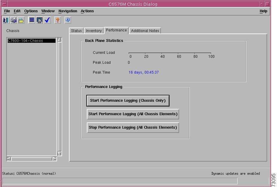
Figure 5-3 shows the Performance tab of the C6576M Chassis dialog box.
Figure 5-3 Performance Tab of the C6576M Chassis Dialog Box
Back Plane Statistics Area
The Back Plane Statistics area of the C6576M Chassis dialog box provides the following information:
•
•
•
The Current Load and Peak Load attributes are polled at the specified interval when the Chassis object is in the Performance state.
Performance Logging Area
The Performance Logging area of the C6576M Chassis dialog box allows users to turn on performance logging for the chassis attributes as well as the attributes of all the chassis elements.
•
•
•
Note
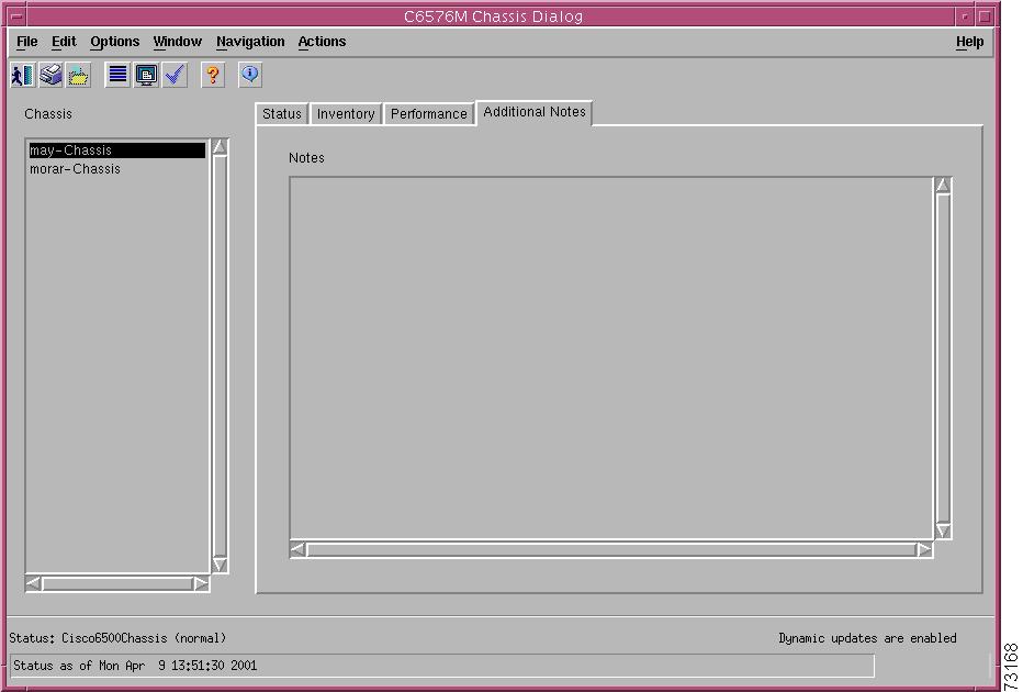
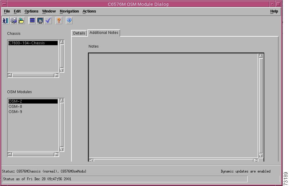
Additional Notes Tab
Figure 5-4 shows the Additional Notes tab of the C6576M Chassis dialog box.
Figure 5-4 Additional Notes Tab of the C6576M Chassis Dialog Box
Notes Area
The Notes area of the C6576M Chassis dialog box is a text box that allows you to type in additional notes for this chassis object. This can be used for providing notes, such as contact information, specifics of the chassis and/or network configurations, warnings, etc.
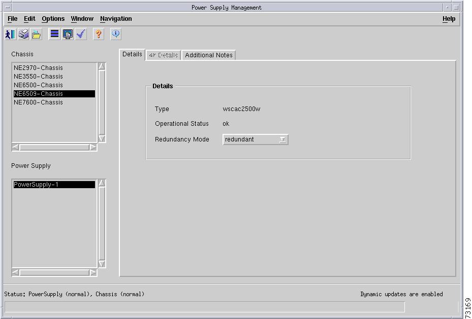
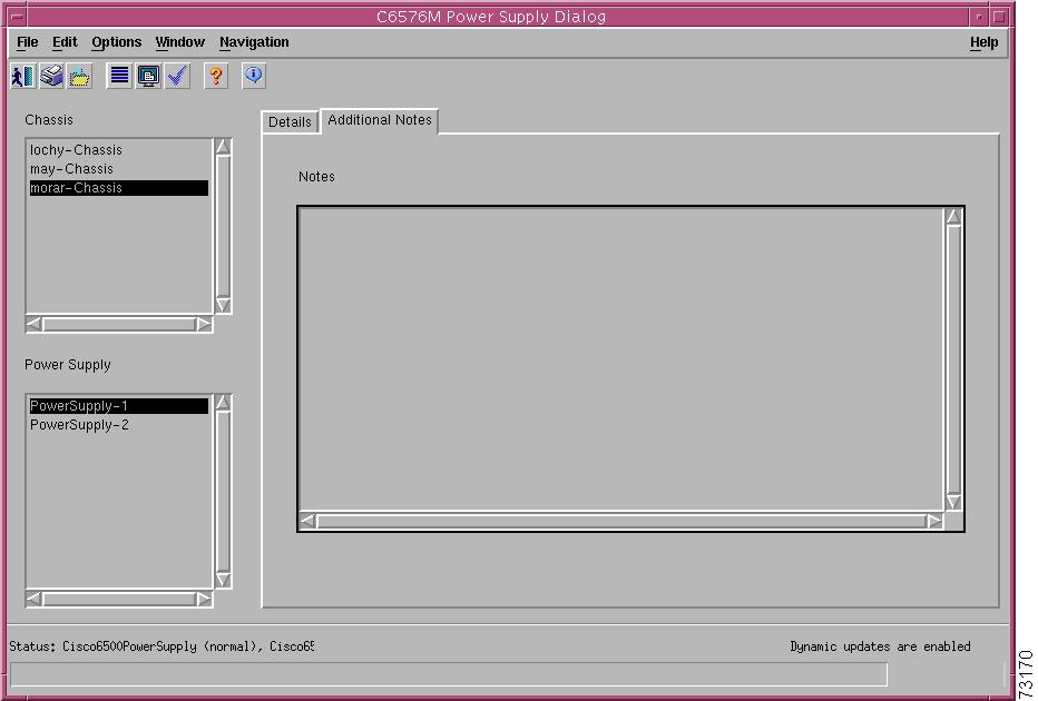
C6576M Power Supply Dialog Box
This dialog box provides access to attributes relating to the power supplies. This dialog box can be launched from a Chassis object or Power Supply objects within the Physical containment view.
You can select multiple Chassis and Power Supply objects at a time from the object list on the left side of the dialog box.
Details Tab
Figure 5-5 shows the Details tab of the C6576M Power Supply dialog box.
Figure 5-5 Details Tab of the C6576M Power Supply Dialog Box
Details Area
The Details area of the C6576M Power Supply dialog box provides the following information:
•
–
–
–
–
–
–
–
–
–
–
–
Note
•
–
–
–
–
Note
•
–
–
Status Field
The display-only Status field located at the bottom of the window indicates the current state of the object. This field can have the following values:
•
•
•
Additional Notes Tab
Figure 5-6 shows the Additional Notes tab of the C6576M Power Supply dialog box.
Figure 5-6 Additional Notes Tab of the C6576M Power Supply Dialog Box
Notes Area
The Notes area is a text box that allows you to type in additional notes for the power supply configuration. For example, the note might include the reason why the power supply is in redundant mode.
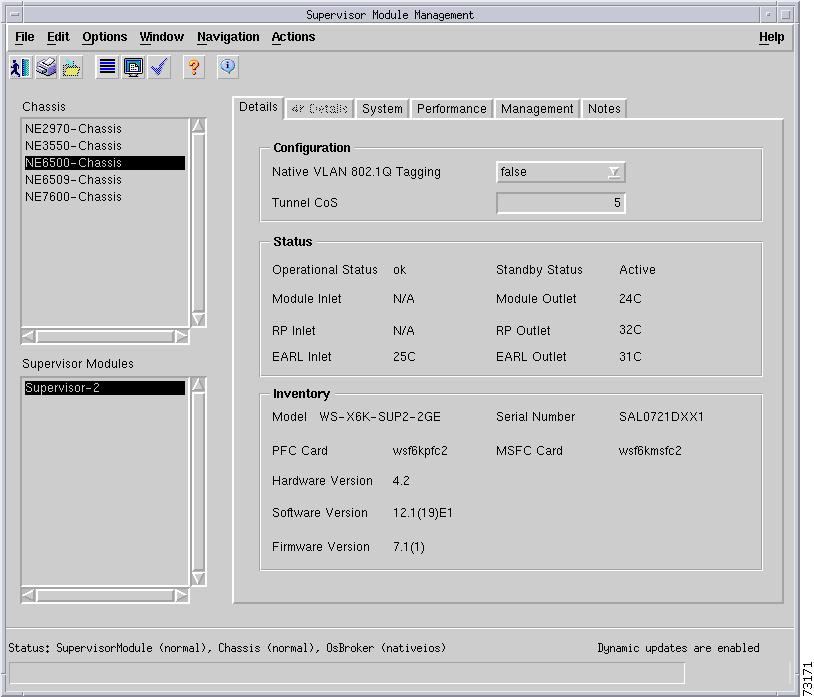
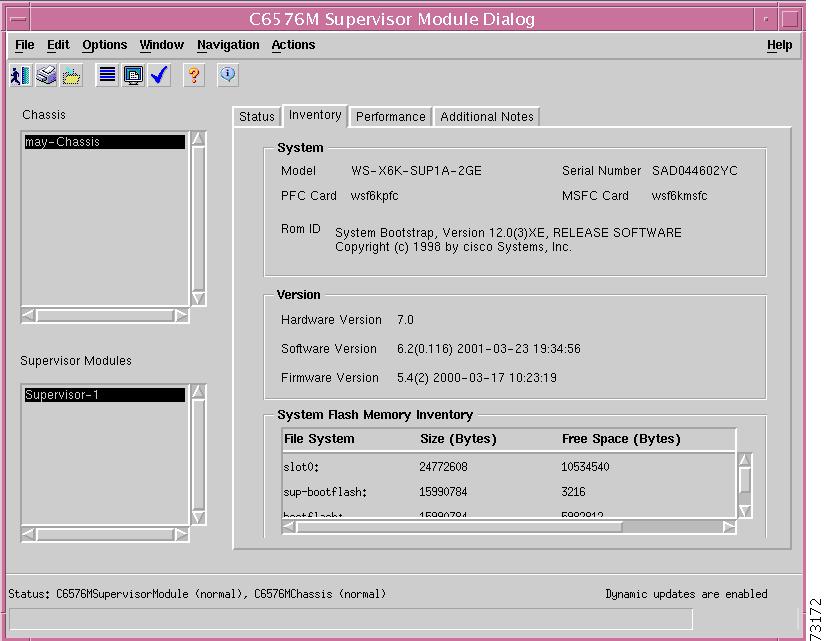
C6576M Supervisor Module Dialog Box
This dialog box provides access to attributes of the supervisor engine modules. This dialog box can be launched from a Chassis object or Supervisor Module object within the Physical view.
You can select one chassis and more than one supervisor engine module at a time from the object list on the left side of the dialog box.
Status Tab
Figure 5-7 shows the Status tab of the C6576M Supervisor Module dialog box.
Figure 5-7 Status Tab of the C6576M Supervisor Module Dialog Box
Status Area
The Status area of the C6576M Supervisor Module dialog box provides the following information:
•
–
–
–
–
Note
•
–
–
–
–
Temperature Area
The Temperature area of the C6576M Supervisor Module dialog box provides the temperature for the following sensors:
•
•
•
•
•
•
Each of these sensor attributes can have the following values:
•
•
•
Actions Area
The Actions area of the C6576M Supervisor Module dialog box provides the following information:
•
•
The decommission action is useful to allow a supervisor engine module to be removed and replaced without generating alarms.
Status Field
The display-only Status field located at the bottom of the window indicates the current state of the object. This field can have the following values:
•
•
•
•
•
•
Inventory Tab
Figure 5-8 shows the Inventory tab of the C6576M Supervisor Module dialog box.
Figure 5-8 Inventory Tab of the C6576M Supervisor Module Dialog Box
System Area
The System area of the C6576M Supervisor Module dialog box provides the following information:
•
•
•
–
–
–
–
•
–
–
–
–
•
Version Area
The Version area of the C6576M Supervisor Module dialog box provides the following information:
•
•
•
System Flash Memory Inventory Area
The System Flash Memory Inventory area lists the Flash memory information for the entire switch (including redundant supervisor engines, if available).
•
•
•
•
Performance Tab
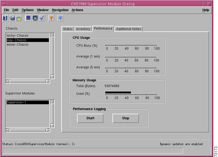
Figure 5-9 shows the Performance tab of the C6576M Supervisor Module dialog box.
Figure 5-9 Performance Tab of the C6576M Supervisor Module Dialog Box
CPU Usage Area
The CPU Usage area of the C6576M Supervisor Module dialog box provides the following information:
•
•
•
Memory Usage Area
The Memory Usage area of the C6576M Supervisor Module dialog box provides the following information:
•
•
Performance Logging Area
The Performance Logging area of the C6576M Supervisor Module dialog box allows users to turn on performance logging for the supervisor module attributes as well as the attributes of the two Gigabit Ethernet interfaces.
•
•
Note
The following Supervisor attributes are polled in the Performance state:
•
•
•
•
•
•
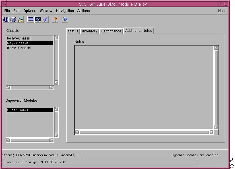
Additional Notes Tab
Figure 5-10 shows the Additional Notes tab of the C6576M Supervisor Module dialog box.
Figure 5-10 Additional Notes Tab of the C6576M Supervisor Module Dialog Box
Notes Area
The Notes area is text box that allows you to type in additional notes for the supervisor engine module.
C6576M Ethernet Module Dialog Box
This dialog box provides information on Ethernet modules, including standard Ethernet, Fast Ethernet, and Gigabit Ethernet modules. This dialog box can be launched from a Chassis object or Ethernet Module object within the Physical view.
You can select one chassis and more than one Ethernet module from the object list on the left side of the dialog box.
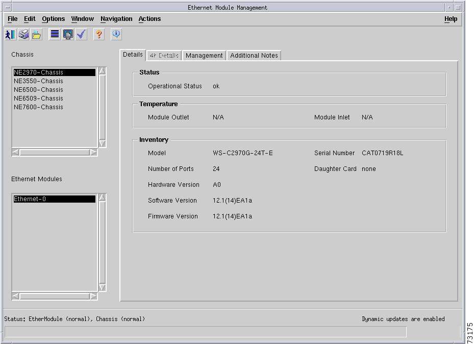
Details Tab
Figure 5-11 shows the Details tab of the C6576M Ethernet Module dialog box.
Figure 5-11 Details Tab of the C6576M Ethernet Module Dialog Box
Status Area
The Status area of the C6576M Ethernet Module dialog box provides the following information:
•
–
–
–
–
Note
Temperature Area
The Temperature area of the C6576M Supervisor Module dialog box provides information for the following sensors:
•
•
Each sensor can have the following values:
–
–
–
Inventory Area
The Inventory area of the C6576M Ethernet Module dialog box provides the following information:
•
–
–
–
–
–
–
–
–
–
–
–
–
–
–
–
–
–
–
–
–
–
•
•
•
–
–
–
–
•
•
•
Performance Logging Area
The Performance Logging area of the C6576M Ethernet Module dialog box allows users to turn on performance data logging for all interfaces on the module:
•
•
See the "C6576M Ethernet Interface Dialog Box" section for a list of the interface attributes that are polled for performance data.
Note
Actions Area
The Actions area of the C6576M Ethernet Module dialog box provides the following information:
•
•
The decommission action is useful to allow a Ethernet module to be removed and replaced without generating alarms.
Status Field
The display-only Status field located at the bottom of the window indicates the current state of the object. This field can have the following values:
•
•
•
•
•
•
Additional Notes Tab
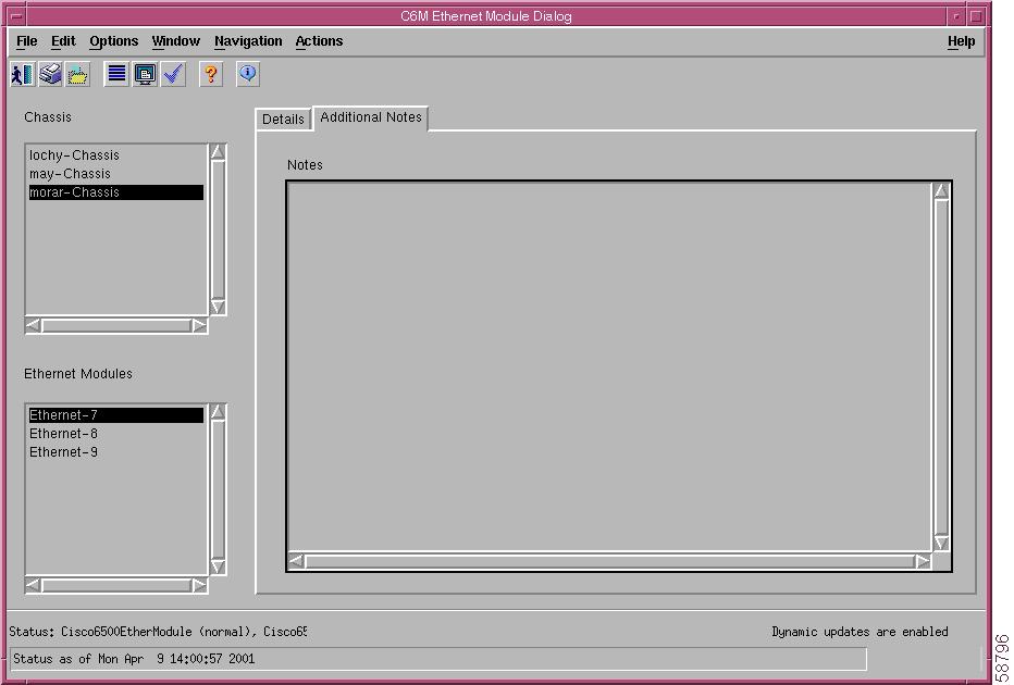
Figure 5-12 shows the Additional Notes tab of the C6576M Ethernet Module dialog box.
Figure 5-12 Additional Notes Tab of the C6576M Ethernet Module Dialog Box
Notes Area
The Notes area is a text box that allows you to type in additional notes for the Ethernet module.
C6576M Ethernet Interface Dialog Box
This dialog box provides information for all Ethernet interface attributes, including Ethernet, Fast Ethernet, and Gigabit Ethernet interfaces. This dialog box can be launched from a Chassis object, Supervisor module object, Ethernet module object, or Ethernet Interface object within the Physical view.
You can select one chassis, more than one Ethernet module, and more than one interface at a time from the object list on the left side of the dialog box.
Status Tab
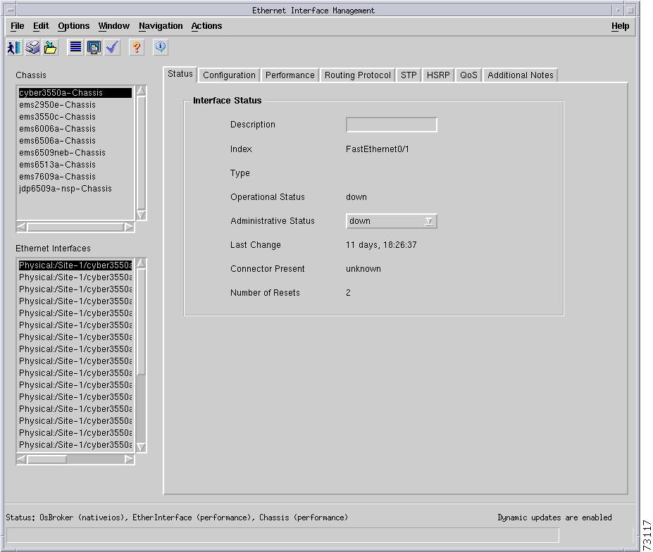
Figure 5-13 shows the Status tab of the C6576M Ethernet Interface dialog box.
Figure 5-13 Status Tab of the C6576M Ethernet Interface Dialog Box
Interface Status Area
The Interface Status area of the C6576M Ethernet Interface dialog box provides the following information:
•
Note
•
•
–
–
–
–
–
–
–
–
–
–
–
–
–
–
–
–
•
–
–
–
–
–
–
–
•
–
–
–
•
•
–
–
–
•
Status Field
The display-only Status field located at the bottom of the window indicates that current state of the object. This field can have the following values:
•
•
•
•
•
Configuration Tab
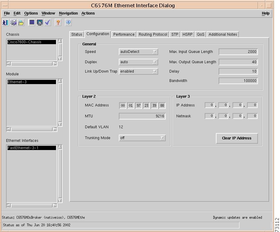
Figure 5-14 shows the Configuration tab of the C6576M Ethernet Interface dialog box.
Figure 5-14 Configuration Tab of the C6576M Ethernet Interface Dialog Box
General Area
The General area of the C6576M Ethernet Interface dialog box provides the following information:
•
–
–
–
–
–
If set to autoDetect, the Duplex attribute is set to auto, which forces the interface to determine the speed and duplex mode for the interface automatically.
Note
•
–
–
–
–
If the Speed attribute is set to autoDetect, the Duplex will be set to auto.
•
–
–
•
•
•
Note
•
Layer 2 Area
The Layer 2 area of the C6576M Ethernet Interface dialog box provides the following information:
•
•
Note
Note
•
•
–
–
–
–
–
Layer 3 Area
The Layer 3 area of the C6576M Ethernet Interface dialog box provides the following information:
•
•
•
Performance Tab
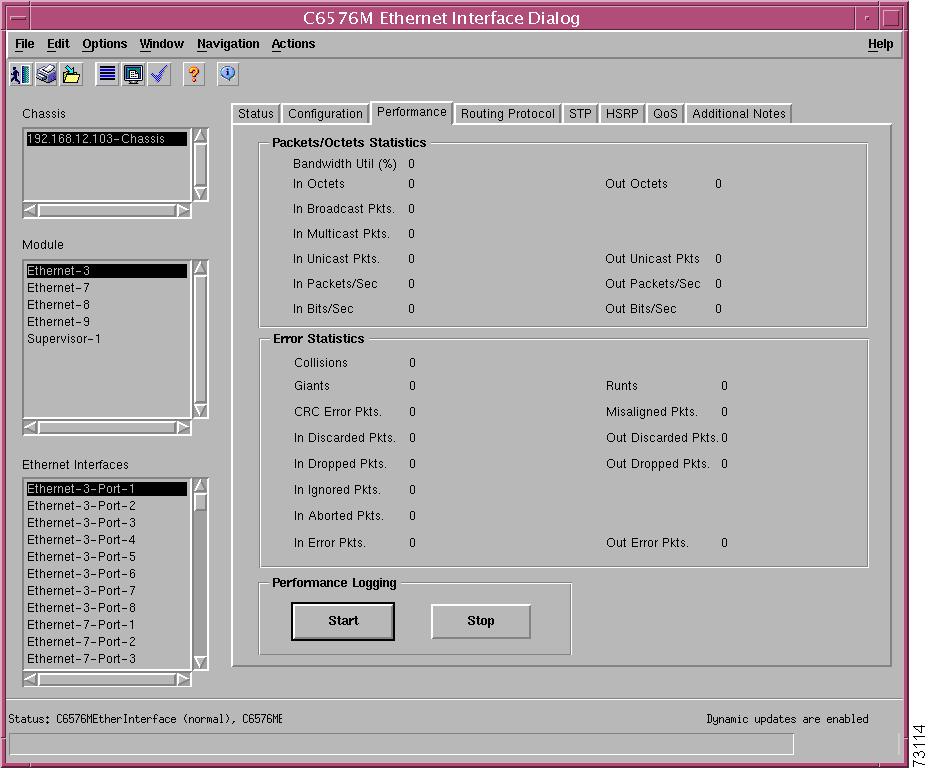
Figure 5-15 shows the Performance tab of the C6576M Ethernet Interface dialog box.
Figure 5-15 Performance Tab on the C6576M Ethernet Interface Dialog Box
Packets/Octets Statistics Area
The Packets/Octets Statistics area C6576M Ethernet Interface dialog box provides the following information:
•
Note
•
•
•
•
•
•
•
•
•
•
Error Statistics Area
The Error Statistics area C6576M Ethernet Interface dialog box provides the following information:
•
•
•
•
•
•
•
•
•
•
•
•
•
Performance Logging Area
The Performance Logging area of the C6576M Ethernet Interface dialog box allows users to turn on performance data logging for a single interface.
•
•
All attributes in the Performance tab are logged when the object is placed into the Performance state.
Note
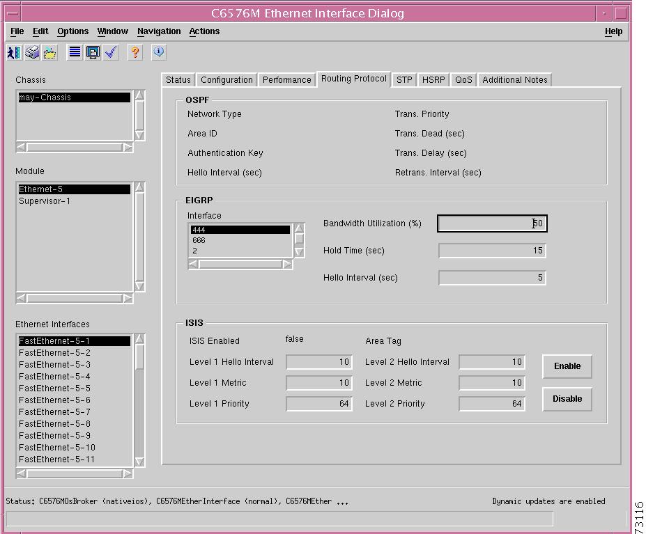
Routing Protocol Tab
Figure 5-16 shows the Routing Protocol tab of the C6576M Ethernet Interface dialog box.
Figure 5-16 Routing Protocol Tab on the C6576M Ethernet Interface Dialog Box
OSPF Area
The OSPF area of the C6576M Ethernet Interface dialog box provides the following information:
•
•
•
•
•
•
•
•
EIGRP Area
The EIGRP Area of the C6576M Ethernet Interface dialog box provides the following information:
•
–
–
–
ISIS Area
The ISIS area of the C6576M Ethernet Interface dialog box provides the following information:
•
–
–
•
•
•
•
•
•
•
•
Note
•
STP Tab
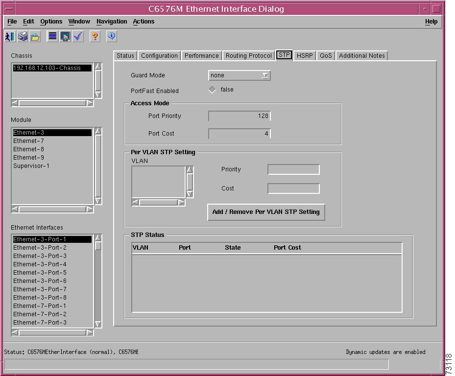
Figure 5-17 shows the STP tab of the C6576M Ethernet Interface dialog box.
Figure 5-17 STP Tab on the C6576M Ethernet Interface Dialog Box
The area at the top of the STP tab provides the following information:
•
–
–
–
•
–
–
Access Mode Area
The Access Mode area of the C6576M Ethernet Interface dialog box provides the following information:
•
–
–
–
–
•
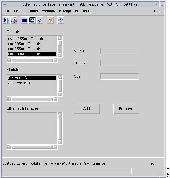
Per VLAN STP Setting Area
The Per VLAN STP Setting area in the STP tab of the C6576M Ethernet Interface dialog box provides the following information:
•
Note
•
–
–
–
–
•
Note
•
–
–
Note
–
–
–
Figure 5-18 Add/Remove Per VLAN STP Setting Subdialog Box
STP Status Area
The STP Status area of the C6576M Ethernet Interface dialog box provides the following information:
•
–
–
–
–
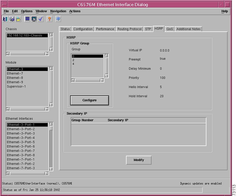
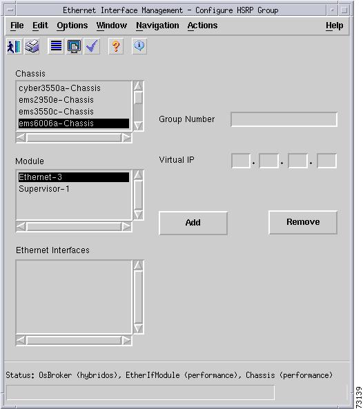
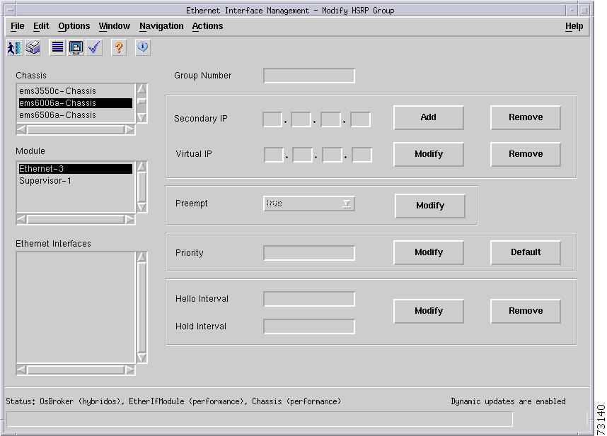
HSRP Tab
Figure 5-19 shows the HSRP tab of the C6576M Ethernet Interface dialog box.
Figure 5-19 HSRP Tab on the C6576M Ethernet Interface Dialog Box
HSRP Area
The HSRP area of the C6576M Ethernet Interface dialog box provides the following information:
•
Note
•
•
–
–
•
•
•
•
•
Figure 5-20 HSRP Group Configure Subdialog Box
Secondary IP Area
The Secondary IP area of the C6576M Ethernet Interface dialog box provides the following information:
•
–
–
•
–
–
–
–
–
–
–
Figure 5-21 HSRP Secondary IP Modify Subdialog Box
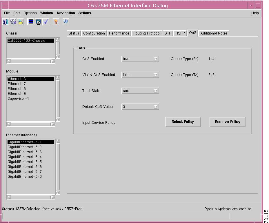
QoS Tab
Figure 5-22 shows the QoS tab of the C6576M Ethernet Interface dialog box.
Figure 5-22 QoS Tab on the C6576M Ethernet Interface Dialog Box
QoS Area
The QoS area of the C6576M Ethernet Interface dialog box provides the following information:
•
–
–
Note
•
–
–
•
–
–
–
–
•
•
•
•
•
–
–
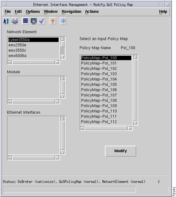
•
Figure 5-23 Select Policy Subdialog Box
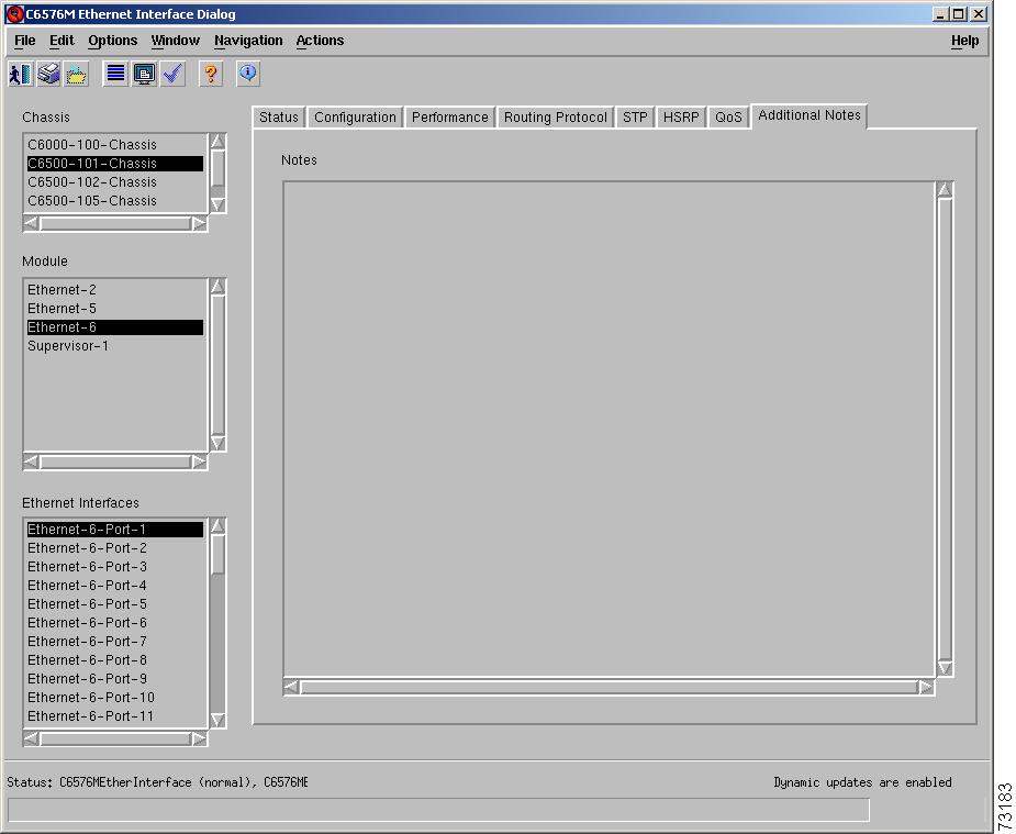
Additional Notes Tab
Figure 5-24 shows the Additional Notes tab of the C6576M Ethernet Interface dialog box.
Figure 5-24 Additional Notes Tab on the C6576M Ethernet Interface Dialog Box
Notes Area
The Notes tab is a text box that allows you to type in additional notes for the interface.
C6576M Switch Fabric Module Dialog Box
This dialog box provides information for the Switch Fabric Modules. This dialog box can be launched from a Chassis object or Switch Fabric Module object within the Physical view.
You can select one chassis and more than one Switch Fabric Module at a time from the object list on the left side of the dialog box.
Details Tab
Figure 5-25 shows the Details tab of the C6576M Switch Fabric Module dialog box. All the attributes displayed in this tab are read-only.
Figure 5-25 Details Tab of the C6576M Switch Fabric Module Dialog Box
Details Area
The Details area of the C6576M Switch Fabric Module dialog box provides the following information:
•
–
–
–
–
Note
•
–
–
–
–
•
–
–
•
•
•
•
Temperature Area
The Temperature area of the C6576M Switch Fabric Module dialog box provides the following information:
•
•
•
•
Actions Area
The Actions area of the C6576M Switch Fabric Module dialog box provides the following actions:
•
•
The decommission action allows a Switch Fabric Module to be removed and replaced without generating alarms.
Status Field
The display-only Status field located at the bottom of the window indicates the current state of the object. This field can have the following values:
•
•
•
•
•
•
Performance Tab
Figure 5-26 shows the Performance tab of the C6576M Switch Fabric Module dialog box.
Figure 5-26 Performance Tab of the C6576M Switch Fabric Module Dialog Box
Statistics Area
The Statistics Table of the Statistics area dialog box provides the fabric channel counters and utilization for the device. There is an entry in this table for each fabric-enabled module installed in the chassis.
•
•
•
•
•
•
•
Note
Additional Notes Tab
Figure 5-27 shows the Additional Notes tab of the C6576M Switch Fabric Module dialog box.
Figure 5-27 Additional Notes Tab of the C6576M Switch Fabric Module Dialog Box
Notes Area
The Notes area is a text box that allows you to type in additional notes for the Switch Fabric Module.
C6576M FlexWAN Module Dialog Box
This dialog box provides information for the FlexWAN modules. This dialog box can be launched from a Chassis object or FlexWAN module object within the Physical view.
You can select one chassis and more than one FlexWAN module at a time from the object list on the left side of the dialog box.
Details Tab
Figure 5-28 shows the Details tab of the C6576M FlexWAN module dialog box.
Figure 5-28 Details Tab of the C6576M FlexWAN Module Dialog Box
Status Area
The Status area of the C6576M FlexWAN Module dialog box provides the following information:
•
–
–
–
–
Note
Inventory Area
The Inventory area of the C6576M FlexWAN Module dialog box provides the following information. All the attributes in this area are read-only.
•
–
•
•
•
•
Performance Logging Area
The Performance Logging area of the C6576M FlexWAN Module dialog box contains these buttons to enable and disable performance logging of the interface attributes of the port adapters (if installed) on the FlexWAN module:
•
•
Note
Actions Area
The Actions area of the C6576M FlexWAN Module dialog box provides the following actions:
•
•
The decommission action allows a FlexWAN module to be removed and replaced without generating alarms.
Status Field
The display-only Status field located at the bottom of the window indicates the current state of the object. This field can have the following values:
•
•
•
•
•
•
Additional Notes Tab
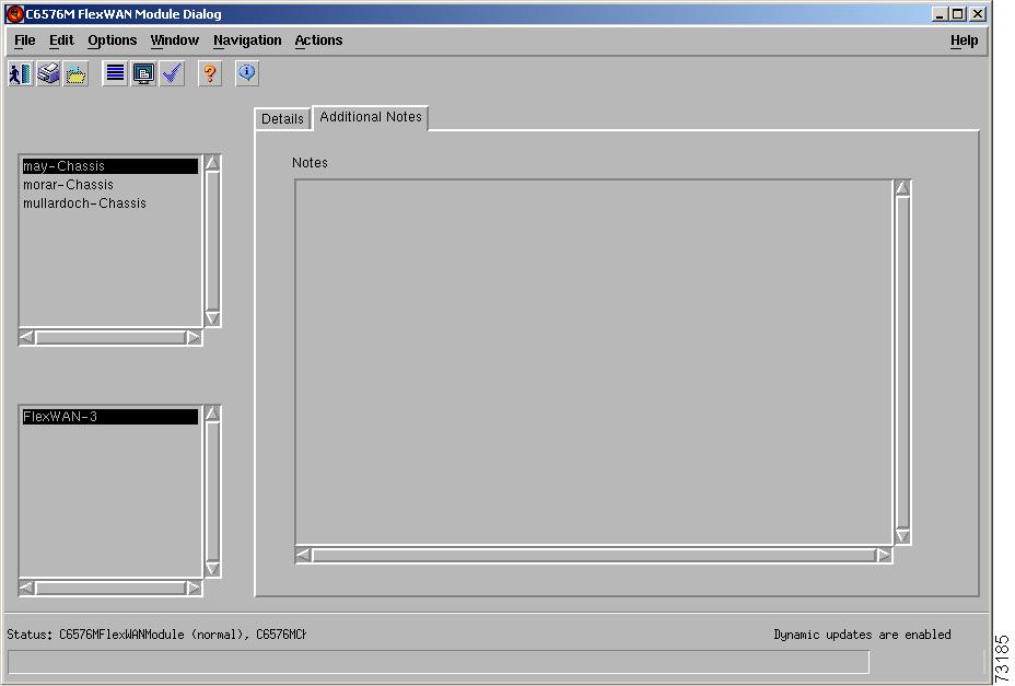
Figure 5-29 shows the Additional Notes tab of the C6576M FlexWAN Module dialog box.
Figure 5-29 Additional Notes Tab of the C6576M FlexWAN Module Dialog Box
Notes Area
The Notes area is a text box that allows you to type in additional notes for the FlexWAN module.
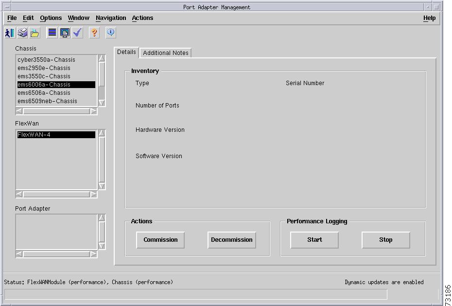
C6576M Port Adapter Dialog Box
This dialog box provides information for the port adapters. This dialog box can be launched from a Chassis object or FlexWAN object within the Physical view.
You can select multiple chassis and port adapters at a time from the object list on the left side of the dialog box.
Details Tab
Figure 5-30 shows the Details tab of the C6576M Port Adapter dialog box.
Figure 5-30 Details Tab of the C6576M Port Adapter Dialog Box
Inventory Area
The Inventory area of the C6576M Port Adapter dialog box provides the following information. All the attributes in this area are read-only.
•
–
–
–
–
–
–
–
–
–
–
–
–
–
–
–
–
–
–
–
–
–
–
–
–
–
•
Note
•
•
•
Performance Logging Area
The Performance Logging area of the C6576M ATM Interface dialog box contains the buttons to enable data logging of all the interface attributes of the port adapter.
•
•
Note
Actions Area
The Actions area of the C6576M Port Adapter dialog box provides the following actions:
•
•
The decommission action allows a port adapter to be removed and replaced without generating alarms.
Status Field
The display-only Status field located at the bottom of the window indicates the current state of the object. This field can have the following values:
•
•
•
•
•
•
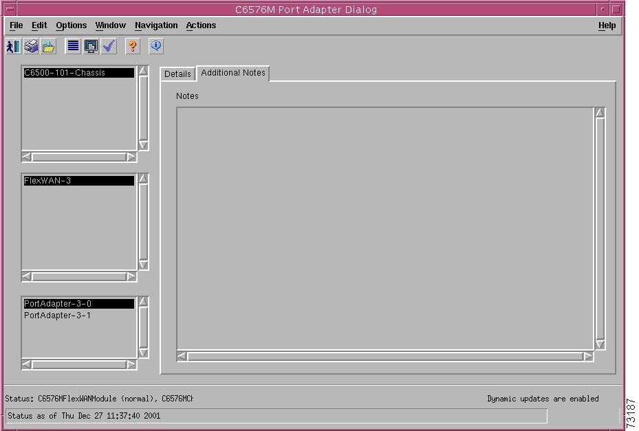
Additional Notes Tab
Figure 5-31 shows the Additional Notes tab of the C6576M Port Adapter dialog box.
Figure 5-31 Additional Notes Tab of the C6576M Port Adapter Dialog Box
Notes Area
The Notes area is a text box that allows you to type in additional notes for the port adapter.
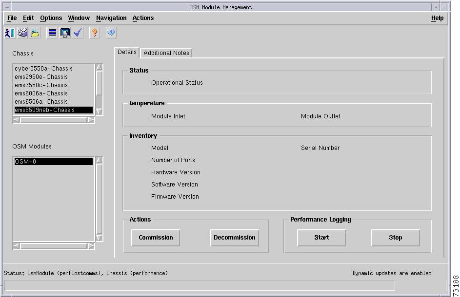
C6576M Optical Services Modules Dialog Box
This dialog box describes the physical Gigabit Ethernet WAN OSM (OSM GE-WAN), Packet over Sonet OSM (OSM PoS), and channelized SONET OSM on a Cisco 7600 series Internet Router. This dialog box can be launched from a Chassis object or an OSM module object within the Physical view.
You can select multiple chassis and OSMs at a time from the object list on the left side of the dialog box.
Details Tab
Figure 5-32 shows the Details tab of the C6576M OSM dialog box.
Figure 5-32 Details Tab of the C6576M OSM Dialog Box
Status Area
The Status area of the C6576M OSM dialog box provides the following information.
•
–
–
–
–
Note
Temperature Area
The Temperature area of the C6576M OSM dialog box provides information for the following sensors. All the attributes in this area are read-only.
•
•
Each sensor can have the following values:
–
–
–
Inventory Area
The Inventory area of the C6576M OSM dialog box provides the following information. All the attributes in this area are read-only.
•
–
–
–
–
–
–
–
–
–
–
–
–
–
–
–
–
–
–
–
–
–
–
–
–
•
•
•
•
Performance Logging Area
The Performance Logging area of the C6576M Port Adapter dialog box contains the buttons to enable data logging of all the interface attributes of the OSM.
•
•
Note
Actions Area
The Actions area of the C6576M OSM dialog box provides the following actions:
•
•
The decommission action allows a OSM to be removed and replaced without generating alarms.
Status Field
The display-only Status field located at the bottom of the window indicates the current state of the object. This field can have the following values:
•
•
•
•
•
•
Additional Notes Tab
Figure 5-33 shows the Additional Notes tab of the C6576M OSM dialog box.
Figure 5-33 Additional Notes Tab of the C6576M OSM Dialog Box
Notes Area
The Notes area is a text box that allows you to type in additional notes for the OSM.
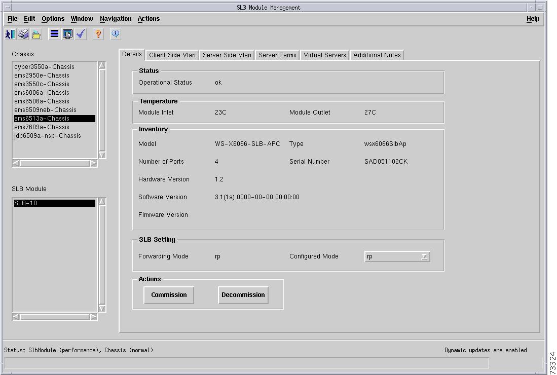
C6576M SLB Dialog Box
The Content Switching Module is a line card that provides server load balancing (SLB) of client traffic to server farms, firewalls, Secure Sockets Layer (SSL) devices, or VPN termination devices. This dialog box provides information for SLB. This dialog box can be launched from a Chassis object or SLB object within the Physical view.
You can select one chassis and one SLB object at a time from the object list on the left side of the dialog box.
Details Tab
Figure 5-34 shows the Details tab of the C6576M SLB dialog box.
Figure 5-34 Details Tab of the C6576M SLB Dialog Box
Status Area
The Status area of the C6576M SLB dialog box provides the following information:
•
–
–
–
–
Note
Temperature Area
The Temperature area of the C6576M SLB dialog box provides information for the following sensors. All the attributes in this area are read-only.
•
•
Each sensor can have the following values:
–
–
–
Inventory Area
The Inventory area of the C6576M SLB dialog box provides the following information. All the attributes in this area are read-only.
•
–
•
•
•
•
•
•
SLB Setting Area
The Inventory area of the C6576M SLB dialog box provides the following information:
•
–
–
•
–
–
Note
Note
Actions Area
The Actions area of the C6576M SLB dialog box provides the following actions:
•
•
The decommission action allows a Content Switching Module to be removed and replaced without generating alarms.
Status Field
The display-only Status field located at the bottom of the window indicates the current state of the object. This field has the following values:
•
•
•
•
•
•
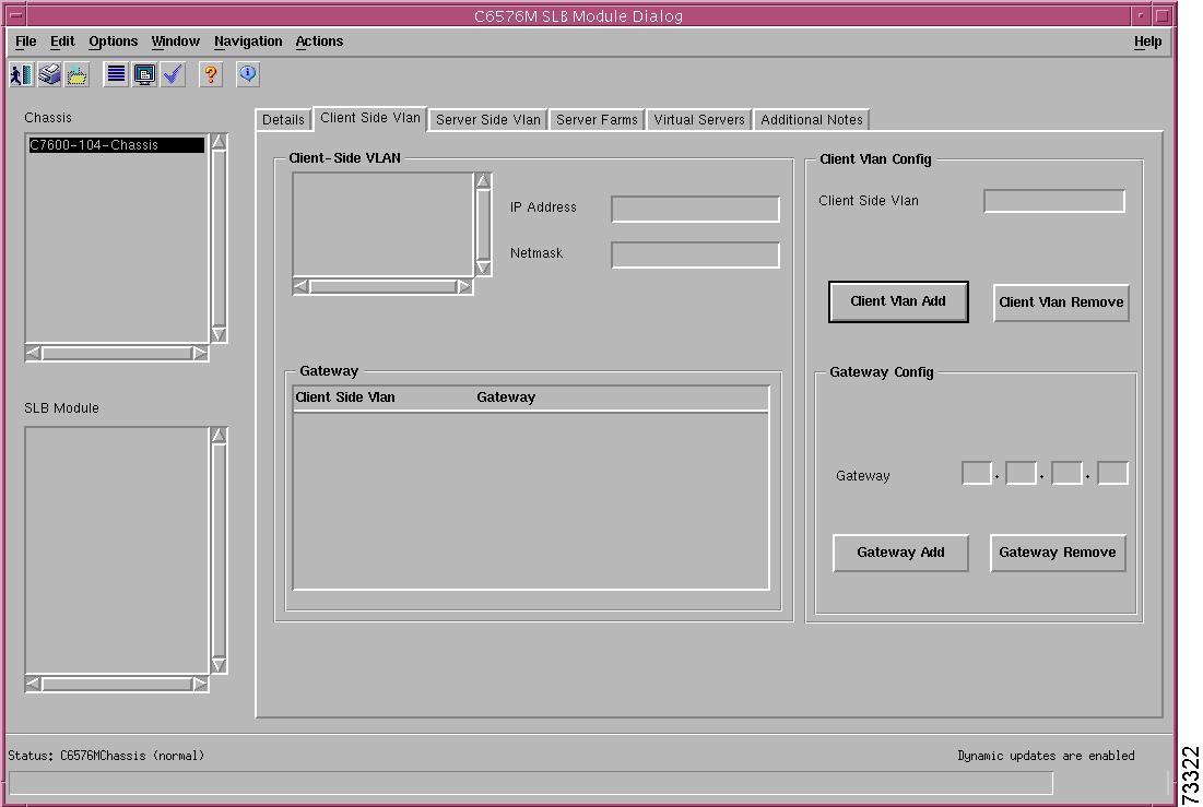
Client Side VLAN Tab
Figure 5-35 shows the Client Side VLAN tab of the C6576M SLB module dialog box.
Figure 5-35 Client Side VLAN Tab of the C6576M SLB Module Dialog Box
Client Side VLAN Area
The Client Side VLAN area of the C6576M SLB dialog box provides the following information:
•
–
–
•
–
–
Client VLAN Config Area
The Client VLAN Config area of the C6576M SLB dialog box allows the user to add client side VLANs. The following attributes are configured:
•
Note
•
•
Gateway Config Subarea
The Gateway Config subarea allows the user to add a default gateways associated with the client VLAN specified in the Client Side VLAN field. This VLAN must already be configured as a client side VLAN.
•
•
•
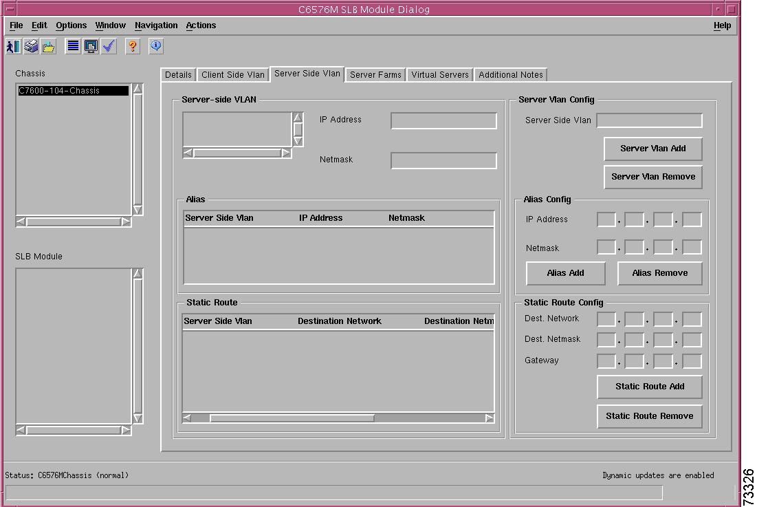
Server Side VLAN Tab
Figure 5-36 shows the Server Side VLAN tab of the C6576M SLB dialog.
Figure 5-36 Server Side VLAN Tab of the C6576M SLB Dialog Box
Server Side VLAN Area
The Server Side VLAN area of the C6576M SLB dialog box provides the following information:
•
–
–
•
–
–
–
•
–
–
–
–
Server VLAN Config Area
The Server VLAN Config area of the C6576M SLB dialog box allows you to add server side VLANs. The following attributes are configured:
•
•
•
Alias Config Subarea
This subarea allows you to add aliases associated with the server VLAN specified in the Server Side VLAN field. This VLAN must already be configured as a Server Side VLAN.
•
•
•
•
Static Route Config Subarea
This subarea allows the user to add static routes of a server VLAN specified in the Server Side VLAN field. This VLAN must already be configured as a server side VLAN.
•
•
•
•
•
For the Static Route Remove and Static Route Add button actions to take effect, you need to specify the static route using one of the following sets of attributes:
•
–
–
–
•
–
–
•
–
–
–
–
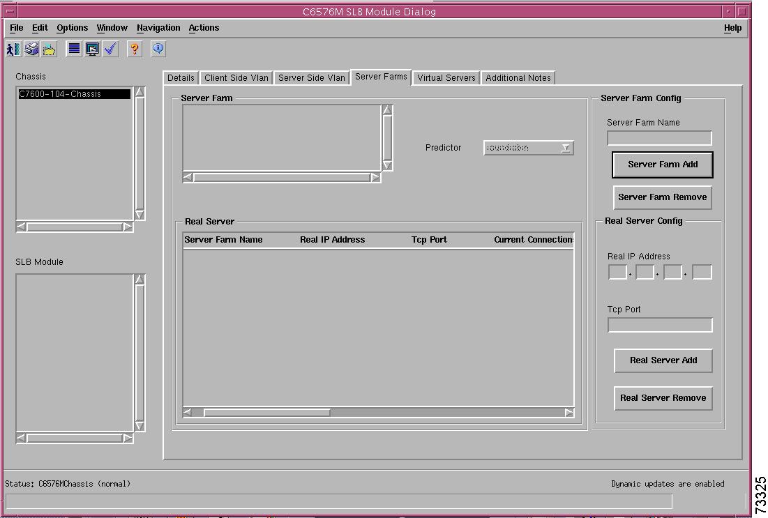
Server Farms Tab
Figure 5-37 shows the Server Farms tab of the C6576M SLB dialog box.
Figure 5-37 Server Farms Tab of the C6576M SLB Dialog Box
Server Farm Area
The Server Farm area of the C6576M SLB dialog box provides the following information:
•
–
–
•
•
•
Note
•
–
–
–
–
–
•
•
•
–
•
•
–
–
–
–
Server Farm Config Area
The Server Farm Config area of the C6576M SLB dialog box allows you to add and configure server farms. The following attributes are configured:
•
•
•
Real Server Config Subarea
This subarea allows the user to add and remove real servers to the server farm specified in the Server Farm Name field.
•
•
•
•
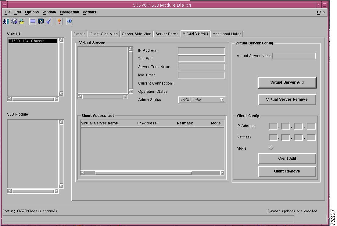
Virtual Servers Tab
Figure 5-38 shows the Virtual Servers tab of the C6576M SLB dialog box.
Figure 5-38 Virtual Servers Tab of the C6576M SLB Dialog Box
Virtual Server Area
The Virtual Server area of the C6576M SLB dialog box allows the user to configure a virtual server to bring it into service.
Note
The following information is provided:
•
–
–
–
•
•
•
•
•
•
•
•
•
•
•
Note
–
–
–
–
•
•
•
–
•
•
•
–
–
–
–
Virtual Server Config Area
The Virtual Server Config area of the C6576M SLB dialog box allows the user to add and configure virtual servers. The following attributes are configured:
•
•
•
Client Config Subarea
•
–
–
Note
–
–
–
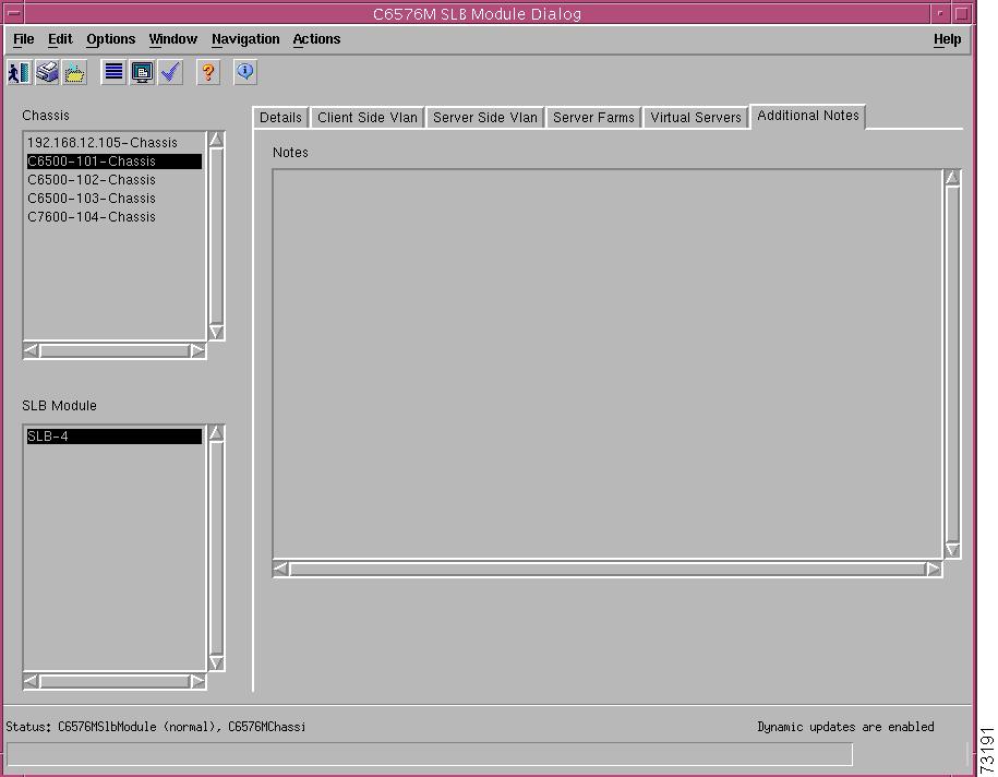
Additional Notes Tab
Figure 5-39 shows the Additional Notes tab of the C6576M SLB dialog box.
Figure 5-39 Additional Notes Tab of the C6576M SLB Dialog Box
Notes Area
The Notes area is a text box that allows you to type in additional notes for the SLB.
C6576M ATM T3 Interface Dialog Box
This dialog box describes a physical and logical enhanced ATM T3 interface of the PA-A3-T3 port adapter on the Catalyst 6000 family switches or Cisco 7600 series Internet Routers. This dialog box is launched from the ATM port adapter or the ATM T3 interface object within the Physical view.
You can select multiple ATM T3 interfaces, port adapters, FlexWAN modules, and chassis at a time from the object list on the left side of the dialog box.
Status Tab
Figure 5-40 shows the Status tab of the C6576M ATM T3 Interface dialog box.
Figure 5-40 Status Tab of the C6576M ATM T3 Interface Dialog Box
Interface Status Area
The Status area of the C6576M ATM T3 Interface dialog box provides the following information to describe the general characteristics of the interface.
•
•
•
–
–
–
–
–
–
–
•
–
–
–
•
•
–
–
–
•
Performance Logging Area
The Performance Logging area of the C6576M ATM T3 Interface dialog box contains the buttons to enable data logging of all the interface attributes of the interface.
•
•
Note
Status Field
The display-only Status field located at the bottom of the window indicates the current state of the object. This field has the following values:
•
•
•
•
•
Configuration Tab
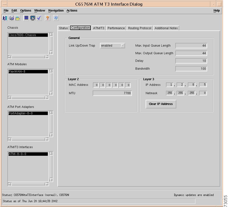
Figure 5-41 shows the Configuration tab of the C6576M ATM T3 Interface dialog box.
Figure 5-41 Configuration Tab of the C6576M ATM T3 Interface Dialog Box
General Area
The General area contains the following information:
•
•
Note
•
Note
•
•
Layer 2 Area
The Layer 2 area contains the following information:
•
•
Layer 3 Area
The Layer 3 area contains the following information:
•
•
•
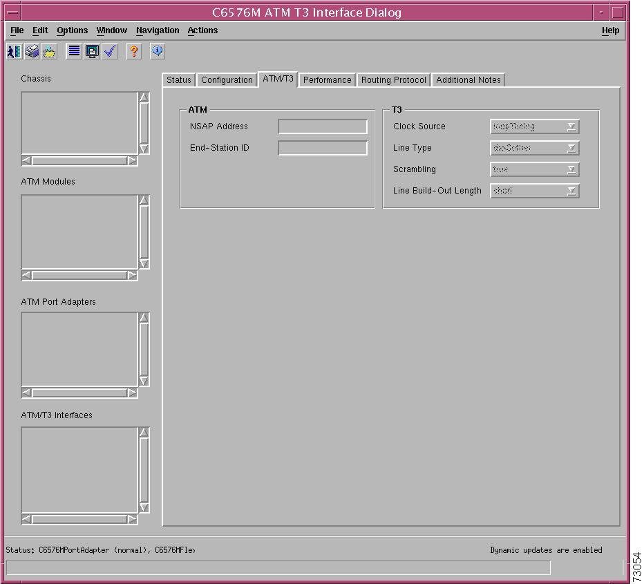
ATM/T3 Tab
Figure 5-42 shows the ATM/T3 tab of the C6576M ATM T3 Interface dialog box.
Figure 5-42 ATM/T3 Tab of the C6576M ATM T3 Interface Dialog Box
ATM Area
The ATM area contains the following information:
•
•
T3 Area
The T3 area contains the following information:
•
–
–
•
–
–
–
–
•
•
–
–
Performance Tab
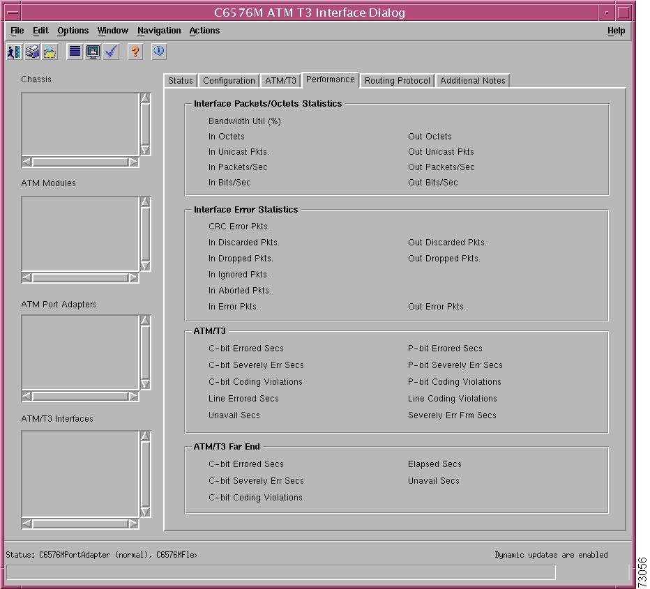
Figure 5-43 shows the Performance tab of the C6576M ATM T3 Interface dialog box.
Figure 5-43 Performance Tab of the C6576M ATM T3 Interface Dialog Box
Interface Packets/Octets Statistics Area
The Interface Packets/Octets Statistics area contains the following information:
•
•
•
•
•
•
•
•
•
Interface Error Statistics Area
The Interface Error Statistics area contains the following information:
•
•
•
•
•
•
•
•
•
ATM/T3 Area
The ATM/T3 area contains the following information:
•
•
•
•
•
•
•
•
•
•
ATM/T3 Far End Area
The ATM/T3 Far End area contains the following information:
•
•
•
•
•
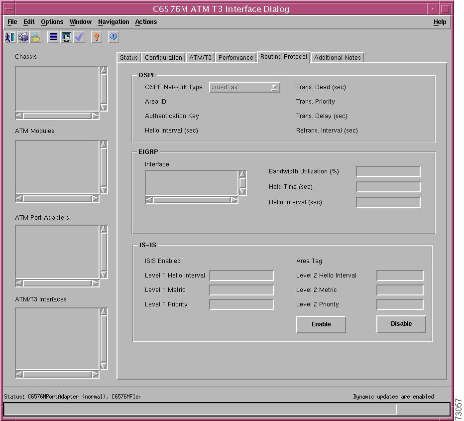
Routing Protocol Tab
Figure 5-44 shows the Routing Protocol tab of the C6576M ATM T3 Interface dialog box.
Figure 5-44 Routing Protocol Tab of the C6576M ATM T3 Interface Dialog Box
OSPF Area
The OSPF area contains the following information:
•
•
•
•
•
•
•
•
EIGRP Area
The EIGRP area describes the EIGRP configuration of the interface on each active autonomous system. This area contains the following information:
•
•
•
•
IS-IS Area
The IS-IS area contains the following information:
•
•
•
•
•
•
•
•
•
Note
•
Note
Additional Notes Tab
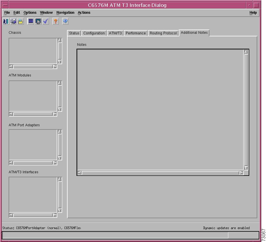
Figure 5-45 shows the Additional Notes tab of the C6576M ATM T3 Interface dialog box.
Figure 5-45 Additional Notes Tab of the C6576M ATM T3 Interface Dialog Box
Notes Area
The Notes area is a text box that allows you to type in additional notes for the ATM T3 Interface.
C6576M ATM E3 Interface Dialog Box
This dialog box describes a physical and logical enhanced ATM E3 interface of the PA-A3-E3 FlexWAN port adapter on the Catalyst 6000 family switches or Cisco 7600 series Internet Routers. This dialog box can be launched from the ATM port adapter or the ATM T3 interface object within the Physical view.
You can select multiple ATM E3 Interfaces, port adapters, FlexWAN modules, and chassis at a time from the object list on the left side of the dialog box.
Status Tab
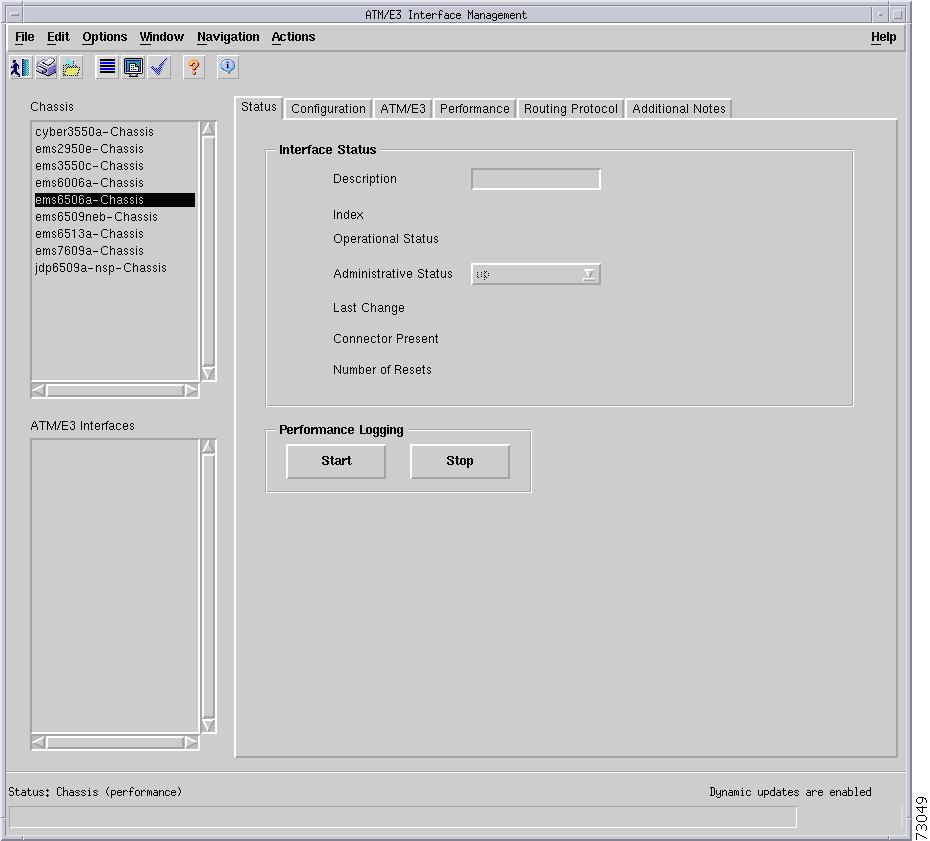
Figure 5-46 shows the Status tab of the C6576M ATM E3 Interface dialog box.
Figure 5-46 Status Tab of the C6576M ATM E3 Interface Dialog Box
Interface Status Area
The Status area of the C6576M ATM E3 Interface dialog box provides the following information to describe the general characteristics of the interface:
•
•
•
–
–
–
–
–
–
–
•
–
–
–
•
•
–
–
–
•
Performance Logging Area
The Performance Logging area of the C6576M ATM E3 Interface dialog box contains the buttons to enable data logging of all the interface attributes of the interface.
•
•
Note
Status Field
The display-only Status field located at the bottom of the window indicates the current state of the object. This field can have the following values:
•
•
•
•
•
Configuration Tab
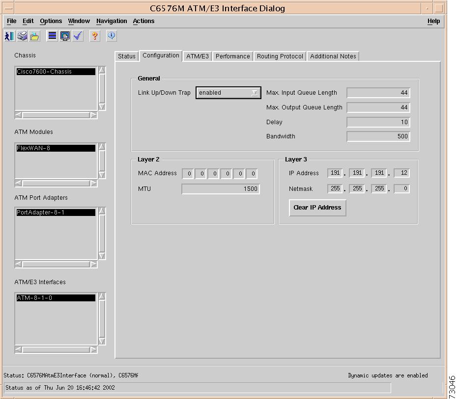
Figure 5-47 shows the Configuration tab of the C6576M ATM E3 Interface dialog box.
Figure 5-47 Configuration Tab of the C6576M ATM E3 Interface Dialog Box
General Area
The General area contains the following information:
•
•
Note
•
Note
•
•
Layer 2 Area
The Layer 2 area contains the following information:
•
•
Layer 3 Area
The Layer 3 area contains the following information:
•
•
•
ATM/E3 Tab
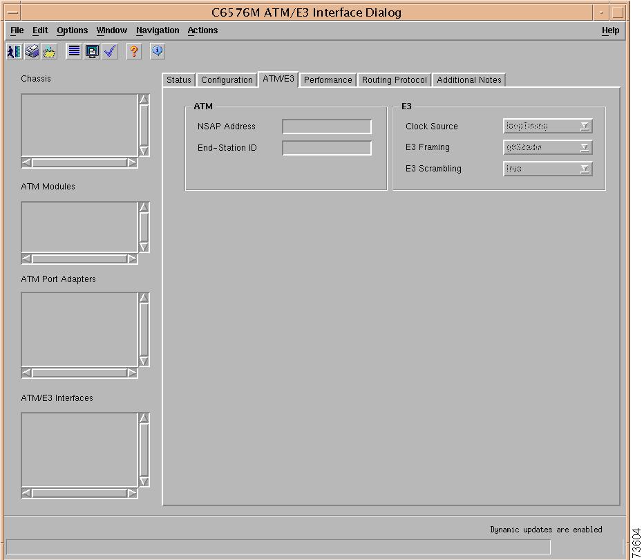
Figure 5-48 shows the ATM/E3 tab of the C6576M ATM E3 Interface dialog box.
Figure 5-48 ATM/E3 Tab of the C6576M ATM E3 Interface Dialog Box
ATM Area
The ATM area contains the following information:
•
•
E3 Area
The E3 area contains the following information:
•
–
–
•
–
–
–
•
Performance Tab
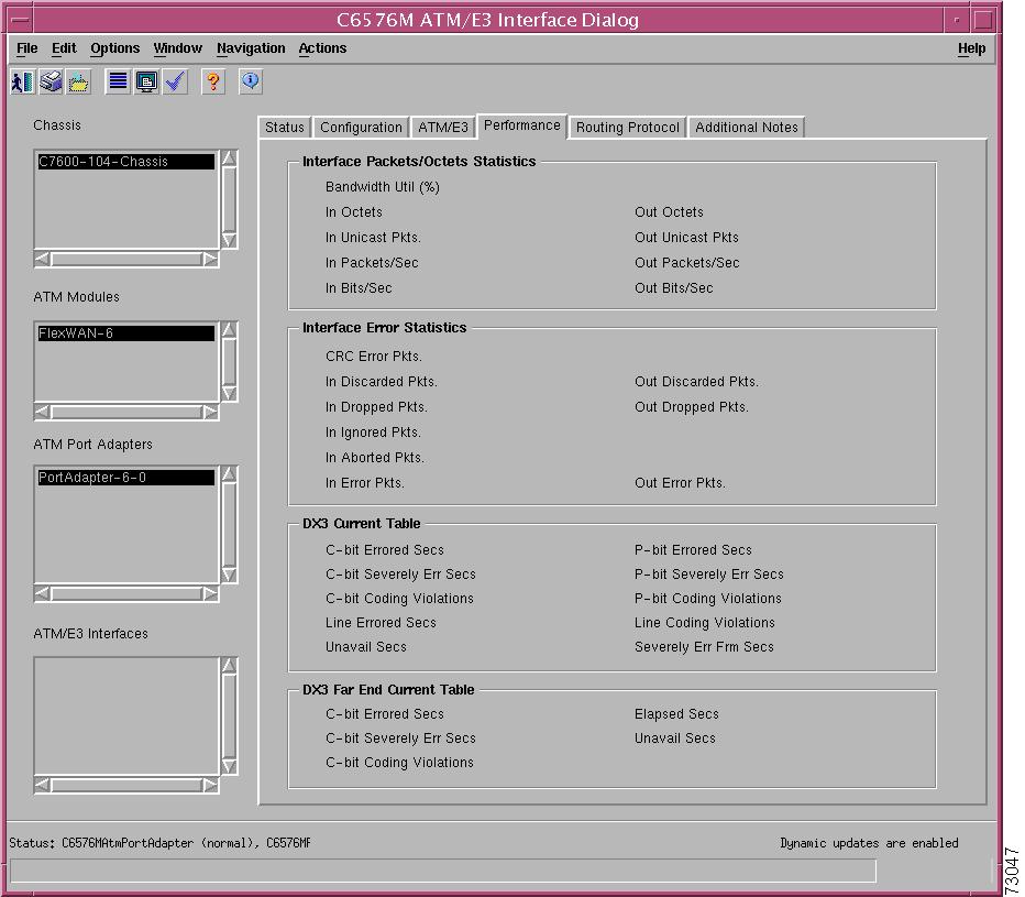
Figure 5-49 shows the Performance tab of the C6576M ATM E3 Interface dialog box. All attributes shown in this tab are read-only.
Figure 5-49 Performance Tab of the C6576M ATM E3 Interface Dialog Box
Interface Packets / Octets Statistics Area
The Interface Packets/Octets Statistics area contains the following information:
•
•
•
•
•
•
•
•
•
Interface Error Statistics Area
The Interface Error Statistics area contains the following information:
•
•
•
•
•
•
•
•
•
DX3 Current Area
The DX3 Current area contains the following information:
•
•
•
•
•
•
•
•
•
•
DX3 Far End Current Area
The DX3 Far End Current area contains the following information:
•
•
•
•
•
Routing Protocol Tab
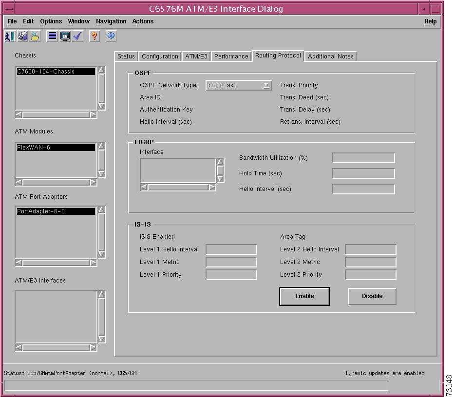
Figure 5-50 shows the Routing Protocol tab of the C6576M ATM E3 Interface dialog box.
Figure 5-50 Routing Protocol Tab of the C6576M ATM E3 Interface Dialog Box
OSPF Area
The OSPF area contains the following information:
•
•
•
•
•
•
•
•
EIGRP Area
The EIGRP area describes the EIGRP configuration of the interface on each active autonomous system. This area contains the following information:
•
•
•
•
IS-IS Area
The IS-IS area contains the following information:
•
•
•
•
•
•
•
•
•
Note
•
Note
Additional Notes Tab
Figure 5-51 shows the Additional Notes tab of the C6576M ATM E3 Interface dialog box.
Figure 5-51 Additional Notes Tab of the C6576M ATM E3 Interface Dialog Box
Notes Area
The Notes area is a text box that allows you to type in additional notes for the ATM E3 Interface.
C6576M ATM SONET Interface Dialog Box
This dialog box describes a physical and logical enhanced ATM OC-3 interface of a FlexWAN port adapter on the Catalyst 6000 family switches or Cisco 7600 series Internet Routers. This dialog box can be launched from the ATM Port Adapter or ATM Sonet interface object within the Physical view.
You can select multiple ATM SONET interfaces, port adapters, FlexWAN modules, and chassis at a time from the object list on the left side of the dialog box.
Status Tab
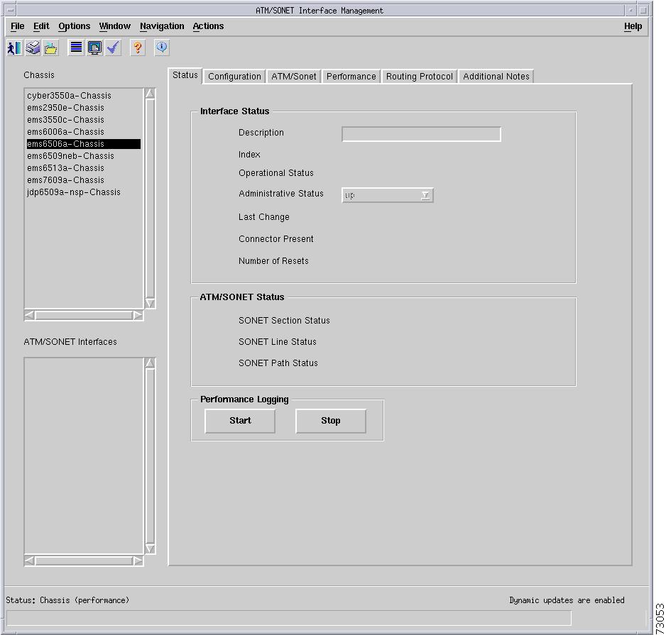
Figure 5-52 shows the Status tab of the C6576M ATM SONET Interface dialog box.
Figure 5-52 Status Tab of the C6576M ATM SONET Interface Dialog Box
Interface Status Area
The Status area of the C6576M ATM SONET Interface dialog box provides the following information to describe the general characteristics of the interface:
•
•
•
–
–
–
–
–
–
–
•
–
–
–
•
•
–
–
–
•
ATM/SONET Area
The ATM/SONET area of the C6576M ATM SONET Interface dialog box provides the following information:
•
–
–
–
•
–
–
–
•
–
–
–
–
–
–
Performance Logging Area
The Performance Logging area of the C6576M ATM T3 Interface dialog box contains buttons to enable data logging of all the interface attributes of the interface:
•
•
Note
Status Field
The display-only Status field located at the bottom of the window indicates the current state of the object. This field has the following values:
•
•
•
•
•
Configuration Tab
Figure 5-53 shows the Configuration tab of the C6576M ATM SONET Interface dialog box.
Figure 5-53 Configuration Tab of the C6576M ATM SONET Interface Dialog Box
General Area
The General area contains the following information:
•
•
Note
•
Note
•
•
Layer 2 Area
The Layer 2 area contains the following information:
•
•
Layer 3 Area
The Layer 3 area contains the following information:
•
•
•
ATM/Sonet Tab
Figure 5-54 shows the ATM/Sonet tab of the C6576M ATM/Sonet Interface dialog box.
Figure 5-54 ATM/Sonet Tab of the C6576M ATM /Sonet Interface Dialog Box
ATM/SONET Configuration Area
The ATM/SONET Configuration area contains the following information:
•
–
–
•
–
–
•
•
•
–
–
SONET Medium Configuration Area
The SONET Medium Configuration area contains the following information. All attributes in this area are read-only.
•
•
–
–
–
•
–
–
–
–
–
Performance Tab
Figure 5-55 shows the Performance tab of the C6576M ATM SONET Interface dialog box. All attributes in this area are read-only.
Figure 5-55 Performance Tab of the C6576M ATM SONET Interface Dialog Box
Interface Packets/Octets Statistics Area
The Interface Packets/Octets Statistics area contains the following information:
•
•
•
•
•
•
•
•
•
Interface Error Statistics Area
The Interface Error Statistics area contains the following information:
•
•
•
•
•
•
•
•
•
SONET Section Error Statistics Area
The SONET Section Error Statistics area contains the following information:
•
•
•
•
SONET Line Error Statistics Area
The SONET Line Error Statistics area contains the following information:
•
•
•
•
SONET Far End Line Error Statistics Area
The SONET Far End Line Error Statistics area contains the following information:
•
•
•
•
SONET Path Error Statistics Area
The SONET Path Error Statistics area contains the following information:
•
•
•
•
SONET Far End Path Error Statistics Area
The SONET Far End Path Error Statistics area contains the following information:
•
•
•
•
Routing Protocol Tab
Figure 5-56 shows the Routing Protocol tab of the C6576M ATM SONET Interface dialog box.
Figure 5-56 Routing Protocol Tab of the C6576M ATM SONET Interface Dialog Box
OSPF Area
The OSPF area contains the following information:
•
•
•
•
•
•
•
•
EIGRP Area
The EIGRP area describes the EIGRP configuration of the interface on each active autonomous system. This area contains the following information:
•
•
•
•
IS-IS Area
The IS-IS area contains the following information:
•
•
•
•
•
•
•
•
•
Note
•
Note
Additional Notes Tab
Figure 5-57 shows the Additional Notes tab of the C6576M ATM SONET Interface dialog box.
Figure 5-57 Additional Notes Tab of the C6576M ATM SONET Interface Dialog Box
Notes Area
The Notes area is a text box that allows you to type in additional notes for the ATM SONET Interface.
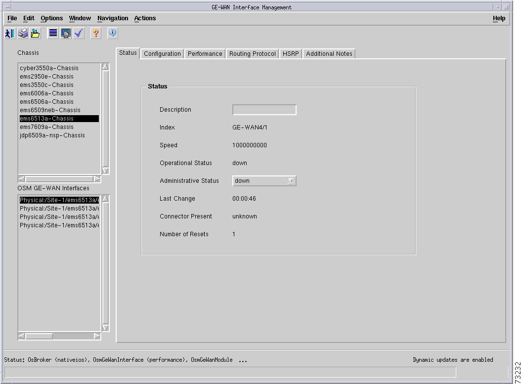
C6576M OSM GE-WAN Interface Dialog Box
This dialog box describes a physical and logical Gigabit Ethernet WAN (GE-WAN) interface on the OSM-4GE-WAN-GBIC module. This dialog box can be launched from the OSM object or OSM GE-WAN Interface object within the Physical view.
You can select multiple OSM GE-WAN Interfaces, OSMs, and chassis at a time from the object list on the left side of the dialog box.
Status Tab
Figure 5-58 shows the Status tab of the C6576M OSM GE-WAN Interface dialog box.
Figure 5-58 Status Tab of the C6576M OSM GE-WAN Interface Dialog Box
Status Area
The Status area of the C6576M OSM GE-WAN Interface dialog box provides the following information to describe the general characteristics of the interface:
•
•
•
•
–
–
–
–
•
–
–
–
•
•
–
–
–
•
Status Field
The display-only Status field located at the bottom of the window indicates the current state of the object. This field has the following values:
•
•
•
•
•
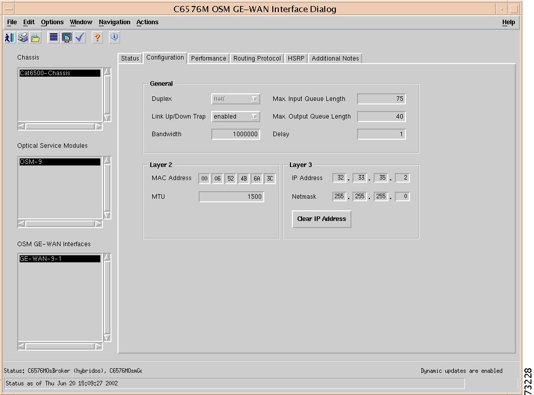
Configuration Tab
Figure 5-59 shows the Configuration tab of the C6576M OSM GE-WAN Interface dialog box.
Figure 5-59 Configuration Tab of the C6576M OSM GE-WAN Interface Dialog Box
General Area
The General area of the C6576M OSM GE-WAN Interface dialog box provides the following information:
•
–
Note
•
–
•
•
•
–
–
•
Note
•
Note
Layer 2 Area
The Layer 2 area of the C6576M OSM GE-WAN interface dialog box provides the following information:
•
•
Note
Note
Layer 3 Area
The Layer 3 area of the C6576M Ethernet Interface dialog box provides the following information:
•
•
•
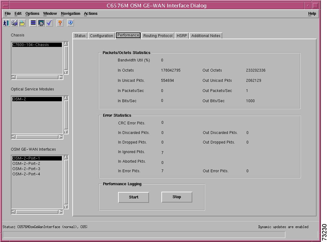
Performance Tab
Figure 5-60 shows the Performance tab of the C6576M OSM GE-WAN Interface dialog box. All attributes in this area are read-only.
Figure 5-60 Performance Tab of the C6576M OSM GE-WAN Interface Dialog Box
Packets/Octets Statistics Area
The Interface Packets/Octets Statistics area contains the following information:
•
•
•
•
•
•
•
•
•
Error Statistics Area
The Interface Error Statistics area contains the following information:
•
•
•
•
•
•
•
•
•
Performance Logging Area
The Performance Logging area of the C6576M OSM GE-WAN Interface dialog box contains buttons to enable data logging of all the interface attributes of the interface:
•
•
Note
Routing Protocol Tab
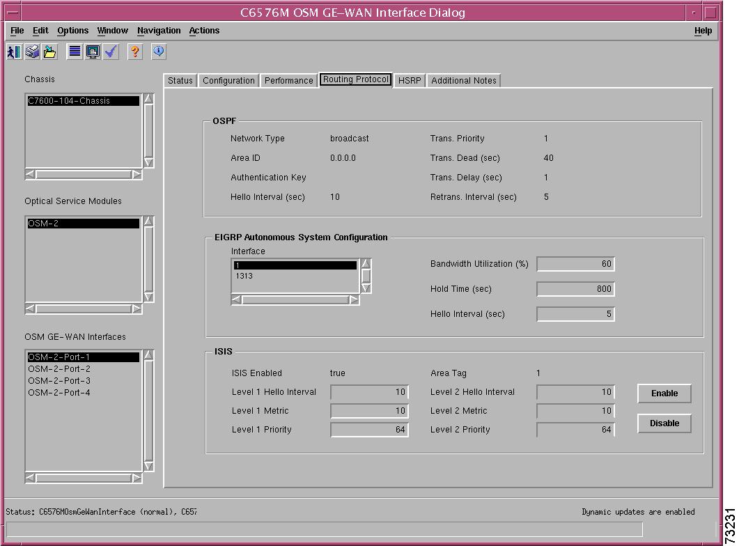
Figure 5-61 shows the Routing Protocol tab of the C6576M OSM GEWAN Interface dialog box.
Figure 5-61 Routing Protocol Tab on the C6576M OSM GE-WAN Interface Dialog Box
OSPF Area
The OSPF area of the C6576M OSM GE-WAN Interface dialog box provides the following information. All the attributes in this area are read-only.
•
–
–
–
–
•
•
•
•
•
•
•
EIGRP Area
The EIGRP Area of the C6576M OSM GE-WAN Interface dialog box provides the following information:
•
•
•
•
ISIS Area
The ISIS area of the C6576M Ethernet Interface dialog box provides the following information:
•
–
–
•
•
•
•
•
•
•
•
Note
•
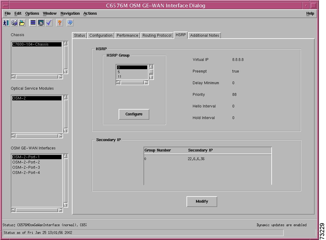
HSRP Tab
Figure 5-62 shows the HSRP tab of the C6576M OSM GE-WAN Interface dialog box. The attributes in this tab are read-only. To modify the attributes, click the Modify button.
Figure 5-62 HSRP Tab on the C6576M OSM GE-WAN Interface Dialog Box
•
–
–
–
–
–
–
–
Figure 5-63 HSRP Secondary IP Modify Subdialog Box
HSRP Area
The HSRP area of the C6576M OSM GE-WAN Interface dialog box provides the following information:
•
Note
•
•
–
–
•
•
•
•
•
–
–
–
–
Figure 5-64 HSRP Group Configure Subdialog Box
Secondary IP Area
The Secondary IP area of the C6576M OSM GE-WAN Interface dialog box provides the following information:
•
–
–
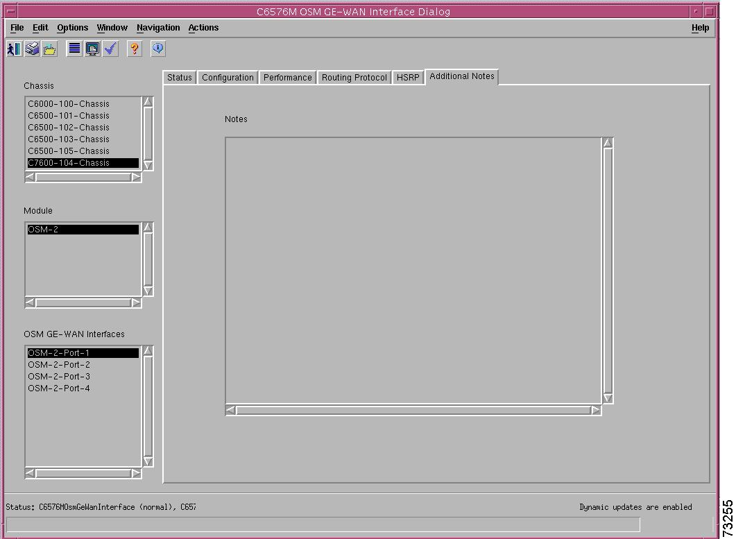
Additional Notes Tab
Figure 5-65 shows the Additional Notes tab of the C6576M OSM GE-WAN Interface dialog box.
Figure 5-65 Additional Notes Tab of the C6576M OSM GE-WAN Interface Dialog Box
Notes Area
The Notes area is a text box that allows you to type in additional notes for the OSM GE-WAN Interface.
C6576M OSM Channelized SONET Interface Dialog Box
This dialog box describes a physical and logical channelized OC-12 (Ch-OC12) or OC-48 (Ch-OC48) SONET interface on an OSM. This dialog box can be launched from the OSM Channelized SONET Module or Interface object within the Physical view.
You can select multiple OSM Channelized SONET Interfaces, OSMs, and chassis at a time from the object list on the left side of the dialog box.
Status Tab
Figure 5-66 shows the Status tab of the C6576M OSM Channelized SONET Interface dialog box.
Figure 5-66 Status Tab of the C6576M OSM Channelized SONET Interface Dialog Box
Interface Status Area
The Status area of the C6576M OSM Channelized SONET Interface dialog box provides the following information to describe the general characteristics of the interface.
•
•
–
–
–
•
•
–
–
–
–
–
–
–
•
–
–
•
•
–
–
–
•
SONET Status Area
The ATM/SONET area of the C6576M OSM Channelized SONET Interface dialog box provides the following information:
•
–
–
–
•
–
–
–
Performance Logging Area
The Performance Logging area of the C6576M OSM Channelized SONET Interface dialog box contains buttons to enable data logging of all the interface attributes of the interface:
•
•
Note
Status Field
The display-only Status field located at the bottom of the window indicates the current state of the object. This field can have the following values:
•
•
•
•
•
Configuration Tab
Figure 5-67 shows the Configuration tab of the C6576M OSM Channelized SONET Interface dialog box.
Figure 5-67 Configuration Tab of the C6576M OSM Channelized SONET Interface Dialog Box
General Area
The General area contains the following information:
•
•
•
SONET Area
The SONET area contains the following information:
•
•
–
–
–
–
–
–
–
•
–
–
–
•
Note
SONET Medium Area
The SONET Medium area contains the following information. All attributes in this area are read-only.
•
•
–
–
–
•
–
–
–
–
–
DS-3/OC-3 Channel Table Area
•
–
–
–
•
–
–
–
–
Note
Figure 5-68 Channel Provision Subdialog Box of the C6576M OSM Channelized SONET Interface Dialog Box
Performance Tab
Figure 5-69 shows the Performance tab of the C6576M OSM Channelized SONET Interface dialog box.
Figure 5-69 Performance Tab of the C6576M OSM Channelized SONET Interface Dialog Box
Interface Packets/ Octets Statistics Area
The Interface Packets/Octets Statistics area contains the following information:
•
•
•
•
•
•
•
•
•
Interface Error Statistics Area
The Interface Error Statistics area contains the following information:
•
•
•
•
•
•
•
•
•
SONET Section Error Statistics Area
The SONET Section Error Statistics area contains the following information:
•
•
•
•
SONET Line Error Statistics Area
The SONET Line Error Statistics area contains the following information:
•
•
•
•
SONET Far End Line Error Statistics Area
The SONET Far End Line Error Statistics area contains the following information:
•
•
•
•
Additional Notes Tab
Figure 5-70 shows the Additional Notes tab of the C6576M OSM Channelized SONET Interface dialog box.
Figure 5-70 Additional Notes Tab of the C6576M OSM Channelized SONET Interface Dialog Box
Notes Area
The Notes area is a text box that allows you to type in additional notes for the OSM Channelized SONET Interface.
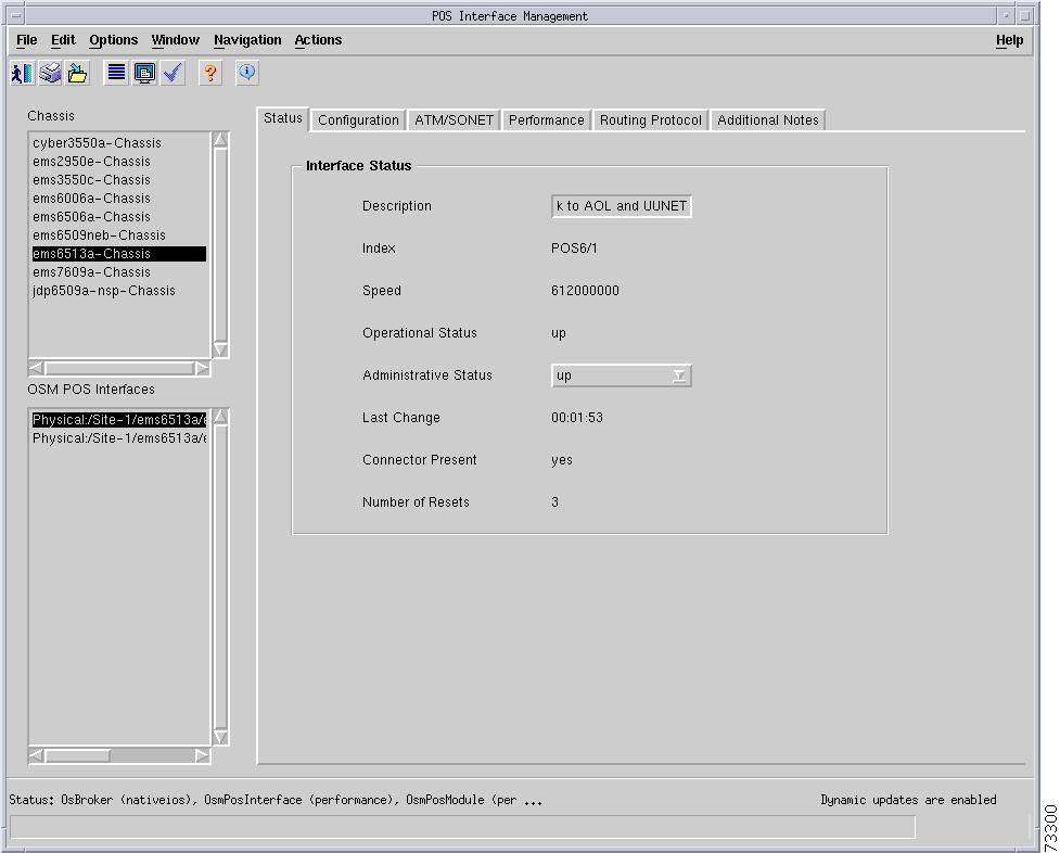
C6576M OSM POS Interface Dialog Box
This dialog box describes a physical and logical PoS interface on an OSM. This dialog box can be launched from the OSM POS Module or Interface object within the Physical view.
You can select multiple OSM POS Interfaces, OSMs, and chassis at a time from the object list on the left side of the dialog box.
Status Tab
Figure 5-71 shows the Status tab of the C6576M OSM POS Interface dialog box.
Figure 5-71 Status Tab of the C6576M OSM POS Interface Dialog Box
Interface Status Area
The Status area of the C6576M OSM POS Interface dialog box provides the following information to describe the general characteristics of the interface:
•
•
•
–
–
–
–
–
–
–
–
–
•
–
–
–
–
•
–
–
•
•
–
–
–
•
Status Field
The display-only Status field located at the bottom of the window indicates the current state of the object. This field can have the following values:
•
•
•
•
•
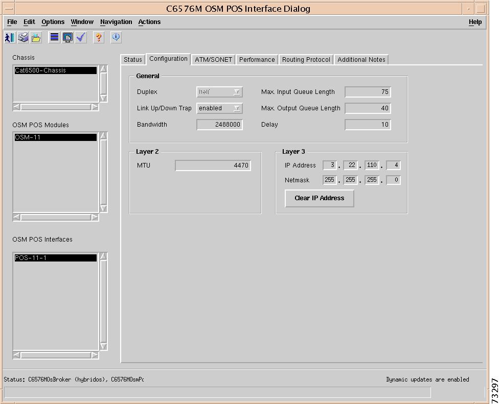
Configuration Tab
Figure 5-72 shows the Configuration tab of the C6576M OSM POS Interface dialog box.
Figure 5-72 Configuration Tab of the C6576M OSM POS Interface Dialog Box
General Area
The General area contains the following information:
•
•
•
•
•
•
Note
•
Note
Layer 2 Area
The Layer 2 area contains the following information:
•
Layer 3 Area
The Layer 3 area contains the following information:
•
•
•
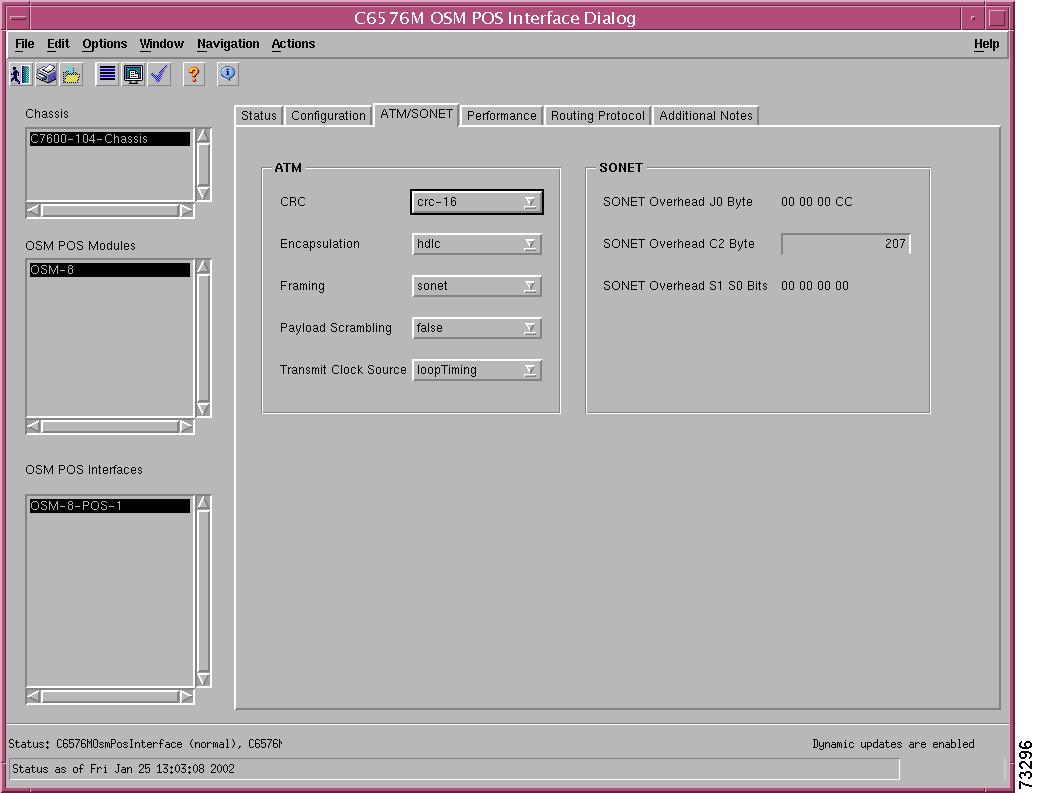
ATM/SONET Tab
Figure 5-73 shows the ATM/SONET tab of the C6576M OSM POS Interface dialog box.
Figure 5-73 ATM/SONET Tab of the C6576M OSM POS Interface Dialog Box
ATM Area
The ATM area contains the following information:
•
•
•
•
•
–
–
SONET Area
The SONET area contains the following information:
•
•
–
–
•
–
–
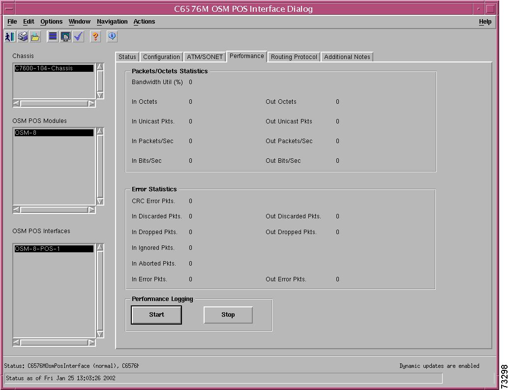
Performance Tab
Figure 5-74 shows the Performance tab of the C6576M OSM POS Interface dialog box. All the attributes in this tab are read-only.
Figure 5-74 Performance Tab of the C6576M OSM POS Interface Dialog Box
Packets/Octets Statistics Area
The Packets/Octets Statistics area contains the following information:
•
•
•
•
•
•
•
•
•
Error Statistics Area
The Error Statistics area contains the following information:
•
•
•
•
•
•
•
•
•
Performance Logging Area
The Performance Logging area of the C6576M OSM POS Interface dialog box contains buttons to enable data logging of all the interface attributes of the interface:
•
•
Note
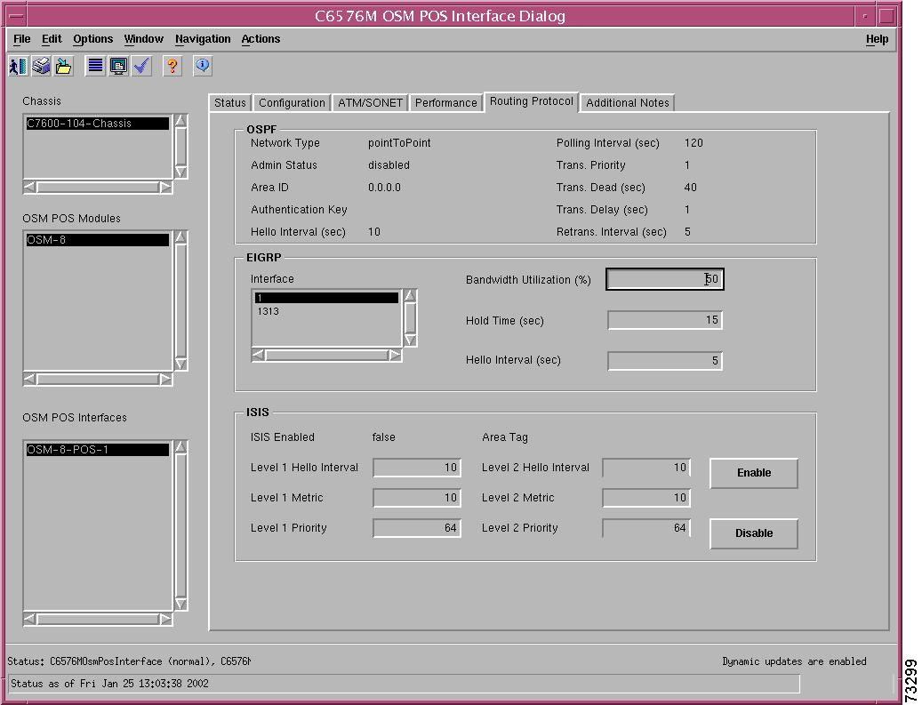
Routing Protocol Tab
Figure 5-75 shows the Routing Protocol tab of the C6576M OSM POS Interface dialog box.
Figure 5-75 Routing Protocol Tab on the C6576M OSM POS Interface Dialog Box
OSPF Area
The OSPF area of the C6576M OSM POS Interface dialog box provides the following information. All the attributes in this area are read-only.
•
–
–
–
–
•
•
•
•
•
•
•
•
•
EIGRP Area
The EIGRP Area of the C6576M OSM POS Interface dialog box provides the following information:
•
•
•
•
ISIS Area
The ISIS area of the C6576M OSM POS Interface dialog box provides the following information:
•
–
–
•
•
•
•
•
•
•
•
Note
•
Note
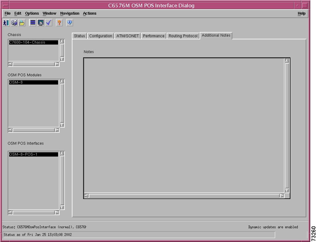
Additional Notes Tab
Figure 5-76 shows the Additional Notes tab of the C6576M OSM POS Interface dialog box.
Figure 5-76 Additional Notes Tab of the C6576M OSM POS Interface Dialog Box
Notes Area
The Notes area is a text box that allows you to type in additional notes for the OSM POS Interface.
C6576M OSM Serial Subinterface Dialog Box
This dialog box describes a logical DS3 channel on a channelized OC-12 (ChOC-12) or OC-48 (ChOC-48) SONET interface of an Optical Service Module (OSM). A DS3 channel of a SONET interface is provisioned as a logical Serial interface. This dialog box can be launched from the OSM Channelized SONET Module or Interface object or the Serial Subinterface object within the Physical view.
You can select multiple OSM serial subinterfaces, OSM Channelized SONET interfaces, OSMs, and chassis at a time from the object list on the left side of the dialog box.
Note
Status Tab
Figure 5-77 shows the Status tab of the C6576M OSM Serial Subinterface dialog box.
Figure 5-77 Status Tab of the C6576M OSM Serial Subinterface Dialog Box
Interface Status Area
The Status area of the C6576M OSM Serial Subinterface dialog box provides the following information to describe the general characteristics of the interface:
•
•
•
–
–
–
–
–
–
•
–
–
•
•
–
–
–
•
Status Field
The display-only Status field located at the bottom of the window indicates the current state of the object. This field has the following values:
•
•
•
•
•
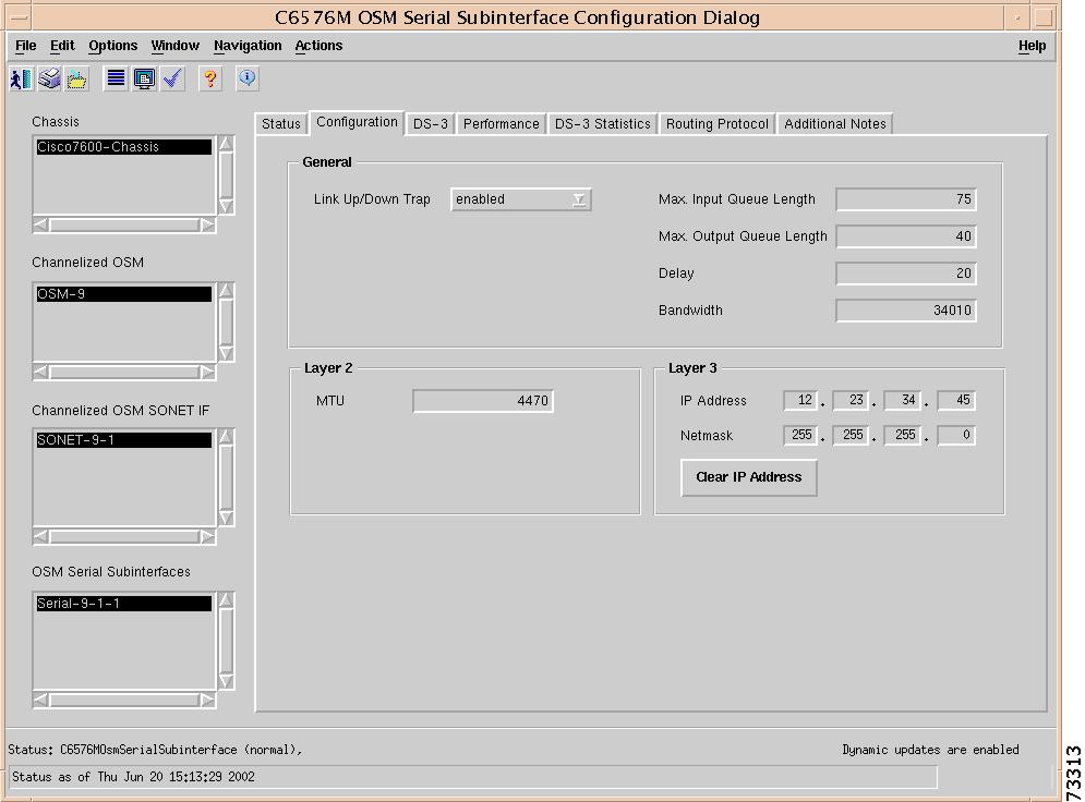
Interface Configuration Tab
Figure 5-78 shows the Interface Configuration tab of the C6576M OSM Serial Subinterface dialog box.
Figure 5-78 Interface Configuration Tab of the C6576M OSM Serial Subinterface Dialog Box
General Area
The General area contains the following information:
•
Note
•
Note
•
•
•
Layer 2 Area
The Layer 2 area contains the following information:
•
Layer 3 Area
The Layer 3 area contains the following information:
•
•
•
DS-3 Configuration Tab
Figure 5-79 shows the DS-3 Configuration tab of the C6576M OSM Serial Subinterface dialog box.
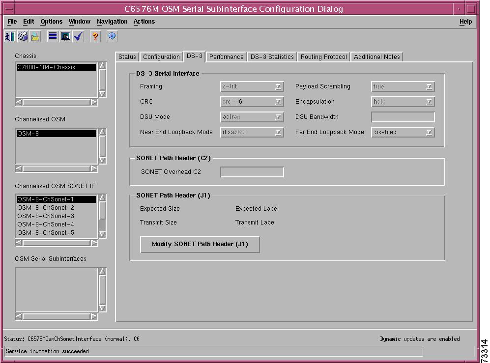
Figure 5-79 DS-3 Configuration Tab of the C6576M OSM Serial Subinterface Dialog Box
DS-3 Serial Interface Area
The DS-3 Serial Interface area contains the following information:
•
•
•
–
–
–
–
–
–
Note
•
–
–
–
•
–
–
•
•
•
SONET Path Header (C2) Area
The SONET Path Header (C2) area contains the following information:
•
–
–
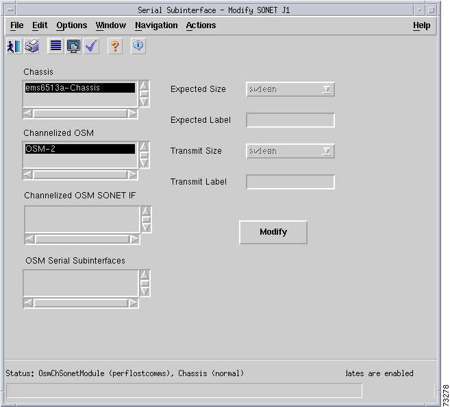
SONET Path Header (J1) Area
The SONET Path Header (J1) area contains the following information:
•
•
•
•
•
–
–
–
–
–
Note
Figure 5-80 SONET J1 Modify Subdialog Box of the C6576M OSM Serial Subinterface Dialog Box
Performance Tab
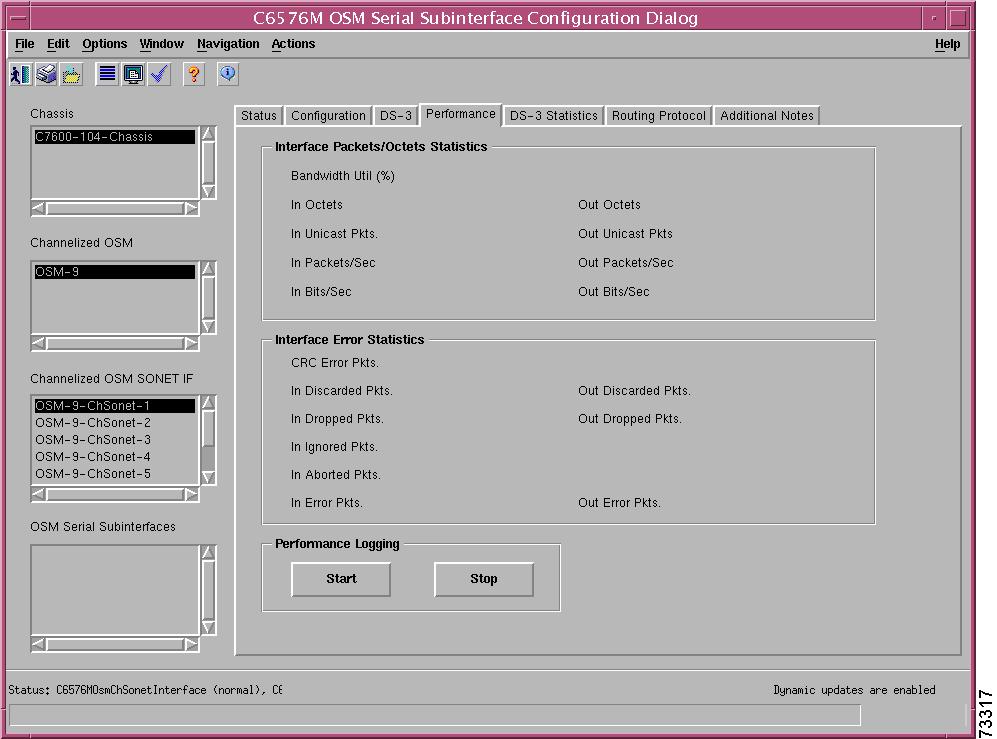
Figure 5-81 shows the Performance tab of the C6576M OSM Serial Subinterface dialog box. All the attributes shown in this tab are read-only.
Figure 5-81 Interface Performance Tab of the C6576M OSM Serial Subinterface Dialog Box
Interface Packets/Octets Statistics Area
The Interface Packets/Octets Statistics area contains the following information:
•
•
•
•
•
•
•
•
•
Interface Error Statistics Area
The Interface Error Statistics area contains the following information:
•
•
•
•
•
•
•
•
•
Performance Logging Area
The Performance Logging area of the C6576M OSM Serial Subinterface dialog box contains these buttons to enable data logging of all the interface attributes of the interface:
•
•
Note
DS-3 Statistics Tab
Figure 5-82 shows the DS-3 Statistics tab of the C6576M OSM Serial Subinterface dialog box.
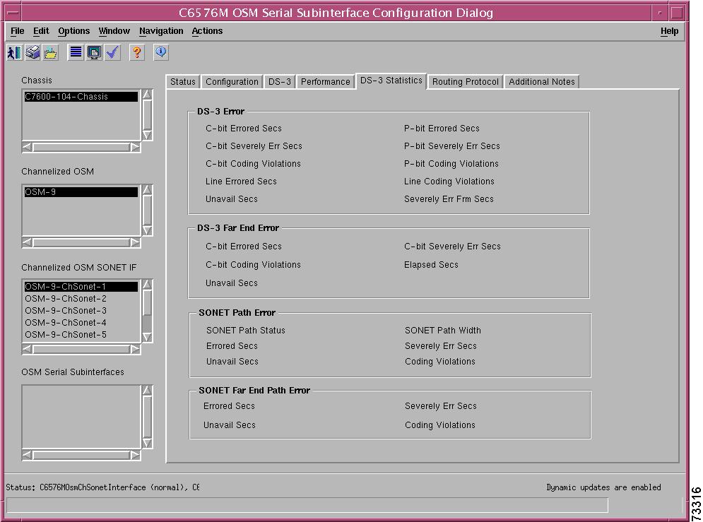
Figure 5-82 DS-3 Statistics Tab on the C6576M OSM Serial Subinterface Dialog Box
DS-3 Error Area
The DS-3 Error area contains the following information:
•
•
•
•
•
•
•
•
•
•
DS-3 Far End Error Area
The DS-3 Far End Error area contains the following information:
•
•
•
•
•
SONET Path Error Area
The SONET Path Error area contains the following information:
•
–
–
–
–
–
•
•
•
•
•
SONET Far End Path Error Area
The SONET Far End Path Error area contains the following information:
•
•
•
•
Routing Protocol Tab
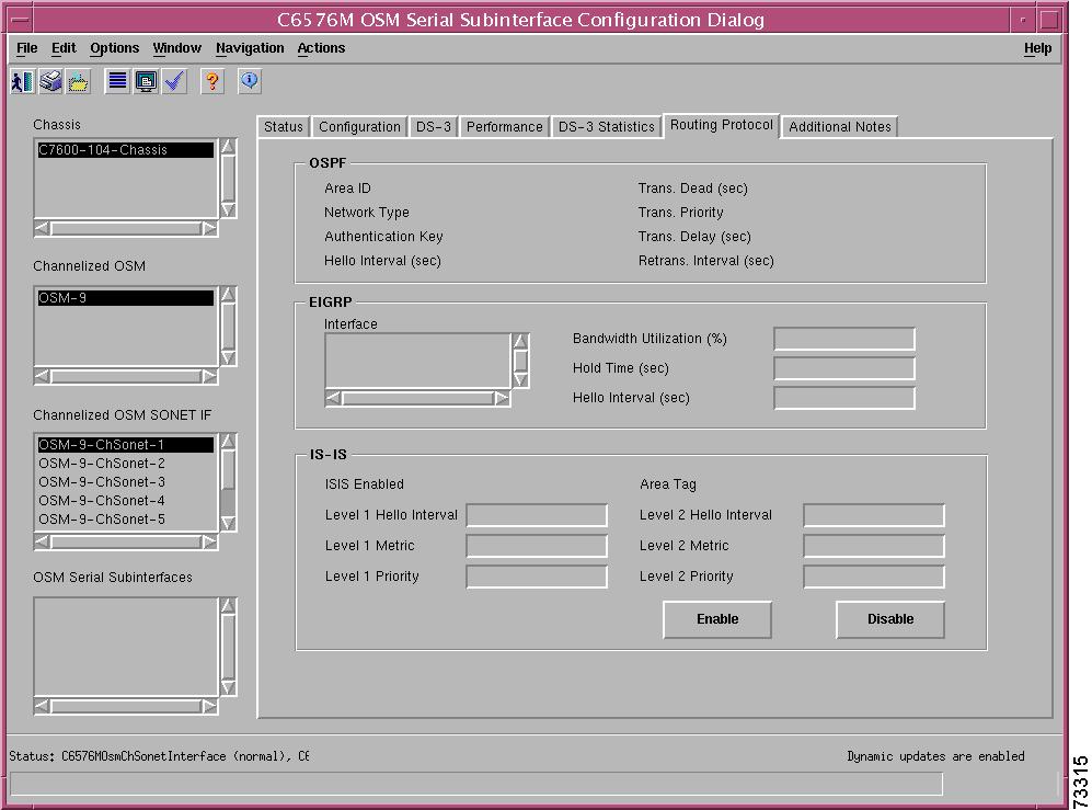
Figure 5-83 shows the Routing Protocol tab of the C6576M OSM Serial Subinterface dialog box.
Figure 5-83 Routing Protocol Tab on the C6576M OSM Serial Subinterface Dialog Box
OSPF Area
The OSPF area of the C6576M OSM POS Interface dialog box provides the following information. All the attributes in this area are read-only.
•
–
–
–
–
•
•
•
•
•
•
•
EIGRP Area
The EIGRP Area of the C6576M Ethernet Interface dialog box provides the following information:
•
•
•
•
ISIS Area
The ISIS area of the C6576M Ethernet Interface dialog box provides the following information:
•
–
–
•
•
•
•
•
•
•
•
Note
•
Note
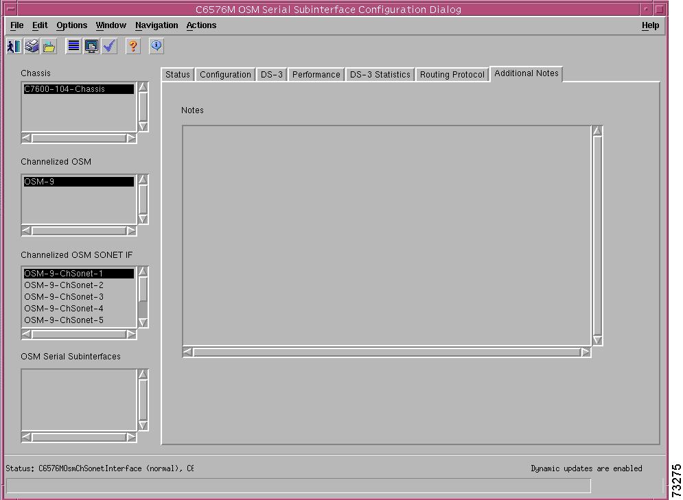
Additional Notes Tab
Figure 5-84 shows the Additional Notes tab of the C6576M OSM Serial Subinterface dialog box.
Figure 5-84 Additional Notes Tab of the C6576M OSM Serial Subinterface Dialog Box
Notes Area
The Notes area is a text box that allows you to type in additional notes for the OSM Serial Subinterface.
C6576M OSM POS Subinterface Dialog Box
This dialog box describes a logical OC-3 channel on a channelized OC-12 (ChOC-12) or OC-48 (ChOC-48) SONET interface of an Optical Service Module (OSM). An OC-3 channel of a SONET interface is provisioned as a logical packet over SONET (POS) interface. This dialog box can be launched from the OSM Channelized SONET Module or Interface object or the POS Subinterface within the Physical view.
You can select multiple OSM POS subinterfaces, OSM Channelized SONET interfaces, OSMs, and chassis at a time from the object list on the left side of the dialog box.
Status Tab
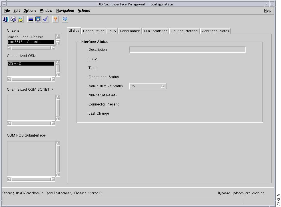
Figure 5-85 shows the Status tab of the C6576M OSM POS Subinterface dialog box.
Figure 5-85 Status Tab of the C6576M OSM POS Subinterface Dialog Box
Interface Status Area
The Status area of the C6576M OSM POS Subinterface dialog box provides the following information to describe the general characteristics of the interface.
•
•
•
•
–
–
–
–
–
–
•
–
–
•
•
–
–
–
•
Status Field
The display-only Status field located at the bottom of the window indicates the current state of the object. This field can have the following values:
•
•
•
•
•
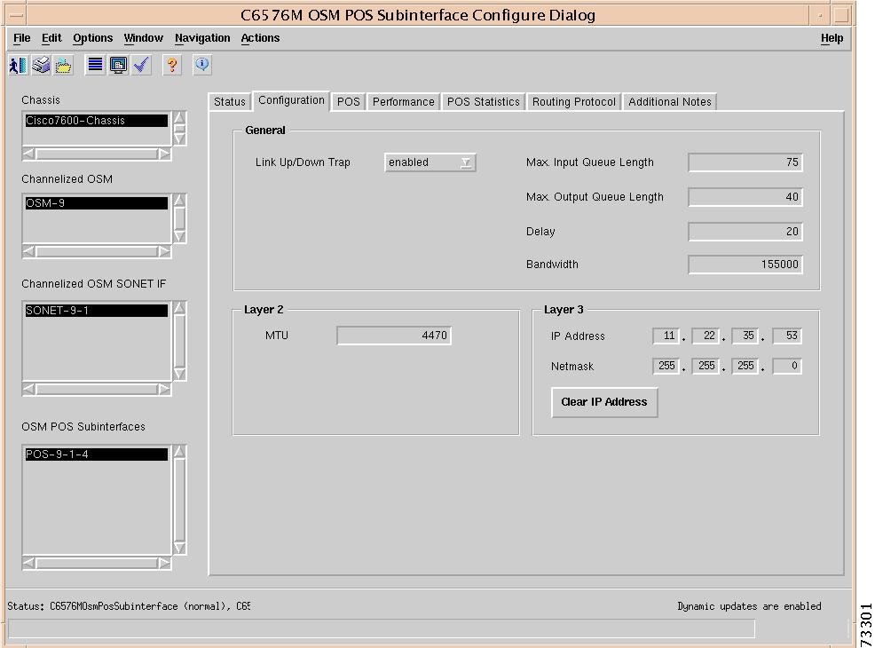
Interface Configuration Tab
Figure 5-86 shows the Interface Configuration tab of the C6576M OSM POS Subinterface dialog box.
Figure 5-86 Interface Configuration Tab of the C6576M OSM POS Subinterface Dialog Box
General Area
The General area contains the following information:
•
Note
•
Note
•
•
•
Layer 2 Area
The Layer 2 area contains the following information:
•
Layer 3 Area
The Layer 3 area contains the following information:
•
•
•
•
–
–
–
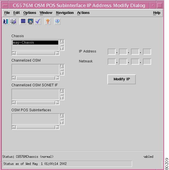
Figure 5-87 Modify IP Subdialog Box
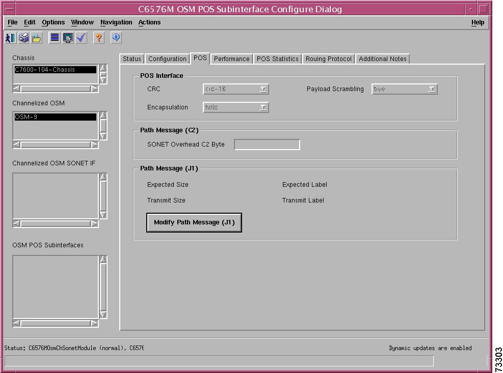
POS Tab
Figure 5-88 shows the POS tab of the C6576M OSM POS Subinterface dialog box.
Figure 5-88 POS Tab of the C6576M OSM POS Subinterface Dialog Box
POS Interface Area
The POS Serial Interface area contains the following information:
•
•
•
Path Message (C2) Area
The Path Message (C2) area contains the following information:
•
–
–
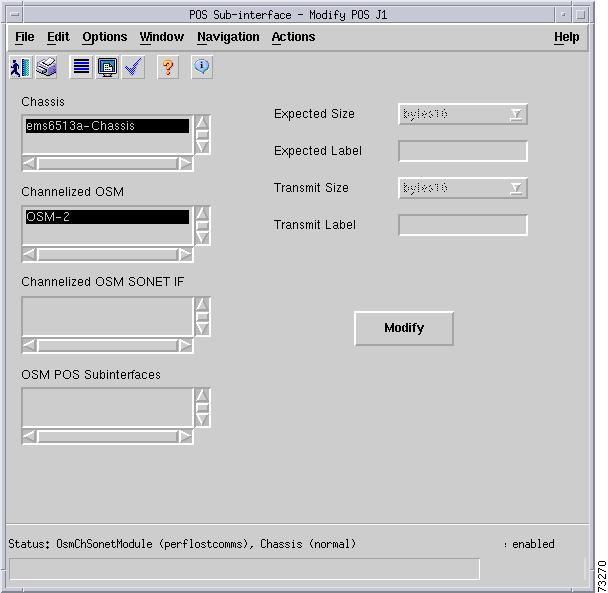
Path Message (J1) Area
The SONET Path Header (J1) area contains the following information:
•
•
•
•
•
–
–
–
–
–
Note
Figure 5-89 SONET J1 Modify Subdialog Box of the C6576M OSM POS Subinterface Dialog Box
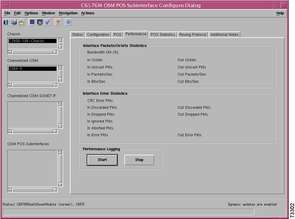
Performance Tab
Figure 5-90 shows the Performance tab of the C6576M OSM POS Subinterface dialog box. All the attributes shown in this tab are read-only.
Figure 5-90 Performance Tab of the C6576M OSM POS Subinterface Dialog Box
Interface Packets/Octets Statistics Area
The Interface Packets/Octets Statistics area contains the following information:
•
•
•
•
•
•
•
•
•
Interface Error Statistics Area
The Interface Error Statistics area contains the following information:
•
•
•
•
•
•
•
•
•
Performance Logging Area
The Performance Logging area of the C6576M OSM POS Subinterface dialog box contains buttons to enable data logging of all the interface attributes of the interface.
•
•
Note
POS Statistics Tab
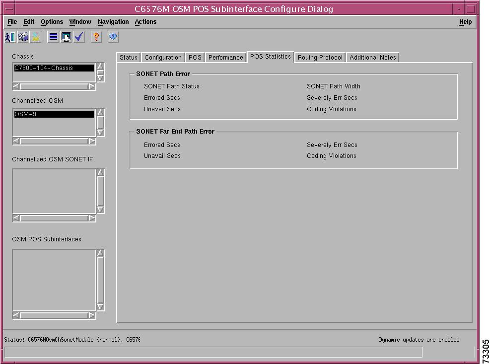
Figure 5-91 shows the POS Statistics tab of the C6576M OSM POS Subinterface dialog box.
Figure 5-91 POS Statistics Tab on the C6576M OSM POS Subinterface Dialog Box
SONET Path Error Area
The SONET Path Error area contains the following information:
•
–
–
–
–
–
–
•
•
•
•
•
SONET Far End Path Error Area
The SONET Far End Path Error area contains the following information:
•
•
•
•
Routing Protocol Tab
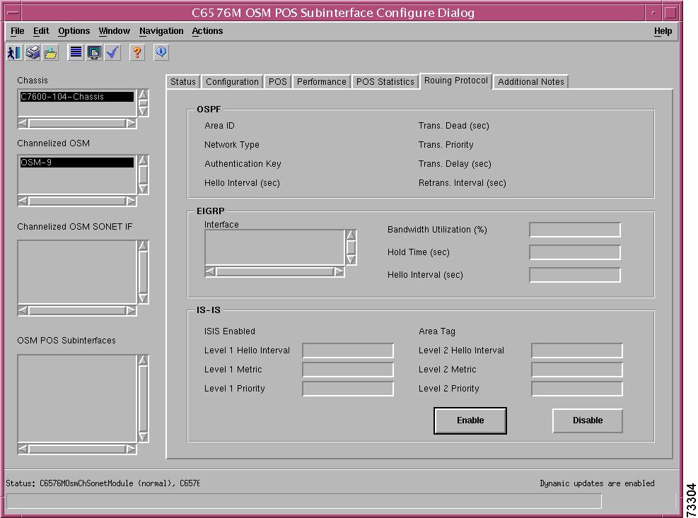
Figure 5-92 shows the Routing Protocol tab of the C6576M OSM POS Subinterface dialog box.
Figure 5-92 Routing Protocol Tab on the C6576M OSM POS Subinterface Dialog Box
OSPF Area
The OSPF area of the C6576M OSM POS Interface dialog box provides the following information. All the attributes in this area are read-only.
•
–
–
–
–
•
•
•
•
•
•
•
EIGRP Area
The EIGRP Area of the C6576M Ethernet Interface dialog box provides the following information:
•
•
•
•
ISIS Area
The ISIS area of the C6576M Ethernet Interface dialog box provides the following information:
•
–
–
•
•
•
•
•
•
•
•
Note
•
Note
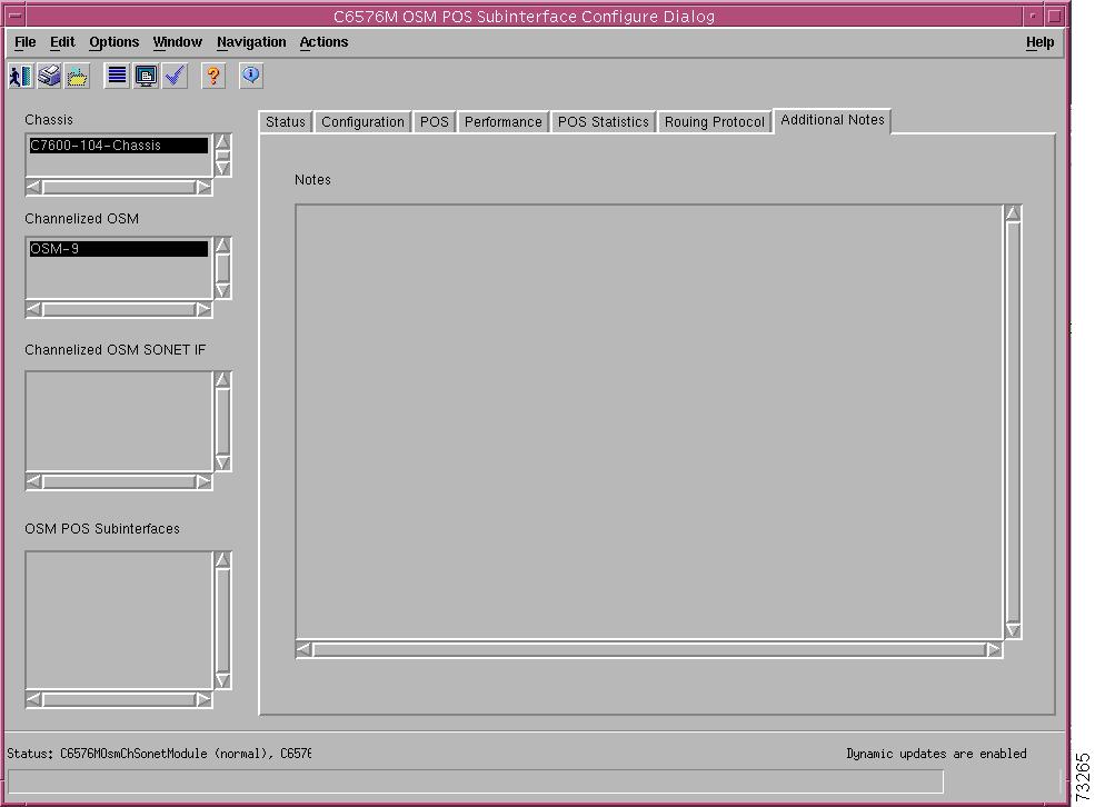
Additional Notes Tab
Figure 5-93 shows the Additional Notes tab of the C6576M OSM POS Subinterface dialog box.
Figure 5-93 Additional Notes Tab of the C6576M OSM POS Subinterface Dialog Box
Notes Area
The Notes area is a text box that allows you to type in additional notes for the OSM POS Subinterface.