Feedback
Table Of Contents
Managing a Catalyst 6000 Family Switch or a Cisco 7600 Series Internet Router
Deployment and Commissioning Process
Network Element, Software, and Chassis Object Predeployment
Predeploying Subchassis Modules
Commissioning Predeployed Objects
Deploying the C65/76M
This chapter describes how to deploy the Cisco 6500/7600 Series Manager, and consists of these sections:
•
Managing a Catalyst 6000 Family Switch or a Cisco 7600 Series Internet Router
•
Managing a Catalyst 6000 Family Switch or a Cisco 7600 Series Internet Router
Managing a Catalyst 6000 family switch or a Cisco 7600 series Internet Router using CEMF is a two-step process:
1.
C65/76M objects can be discovered automatically or deployed manually.
2.
Deploying Objects
The deployment process should be done after you install the C65/76M software for the first time, or after you install new hardware. Deployment informs the C65/76M of the presence of supported hardware.
The C65/76M objects can be automatically discovered or manually deployed. Objects can also be predeployed in CEMF before the actual installation of a Catalyst 6000 family switch or a Cisco 7600 series Internet Router in the field.
Predeployment is the process of reserving a space in CEMF for network equipment, which has not yet been physically slotted into the system rack. When an object or device is predeployed, the physical device or object is not present, but CEMF has been preconfigured to hold an object of similar type. As a result, C65/76M module objects can be deployed and the C65/76M will not monitor their status. When a module is then placed in the physical equipment, the new module will be automatically detected and management of the module will be automatically started.
C65/76M Object Hierarchy
A fully deployed C65/76M object in CEMF has the following object hierarchy:
Network ElementChassisPower SuppliesSupervisor ModulesEthernet InterfacesEthernet ModulesEthernet InterfacesSwitch Fabric ModulesFlexWAN ModulesPort AdapterATM Port AdapterATM SONET InterfacesATM E3 InterfacesATM T3 InterfacesOSM GeWAN ModulesOSM GeWAN InterfacesOSM PoS ModulesEthernet InterfacesOSM PoS InterfacesOSM Channelized SONET ModulesEthernet InterfacesOSM Channelized SONET InterfacesOSM Serial Sub-interfacesOSM PoS Sub-interfacesContent Switching ModulesSoftwareEtherChannelsSyslogEIGRPBGPOSPFVTPVLANSTPIS-ISACLNDELoopbackQoSQoS Policy MapThe top-level Network Element object represents the entire switch including the physical and logical components of the switch. The Chassis object, which is a child of the Network Element object, represents all the physical components of the switch. For example, the chassis frame, power supplies, modules, and ports are all represented under the Chassis object. The Software object, which is a peer of the Chassis object, represents all the logical components of the switch. For example, VLAN configurations, EtherChannels, and routing protocols are represented under the Software object.
Note
Commissioning Objects
Commissioning is the action required to notify CEMF to start actively monitoring the object. Only the following C65/76M objects can be commissioned and decommissioned by the user:
•
•
•
•
•
•
•
•
When applied to these objects, the commissioning process is propagated down to all the object's children. For example, if the Network Element object is commissioned, all the C65/76M objects are also commissioned. If only a Supervisor Module object is commissioned, then its Ethernet Interface objects are also commissioned.
When the Network Element object is commissioned, a subchassis discovery is started to determine the contents of the switch. If objects on the switch are discovered that do not currently exist in CEMF, then these objects are automatically created and populated. For example, an Ethernet module would be automatically populated with the appropriate number of interfaces when it is discovered. If the object already exists in CEMF, then a type match is made against the CEMF object and the one found during discovery. If a mismatch is found, the object is placed into the Mismatched state and an error is generated. If there is no mismatch, then the object is commissioned successfully and CEMF begins to monitor it.
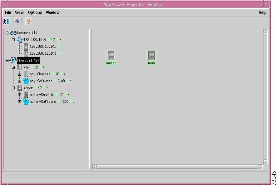
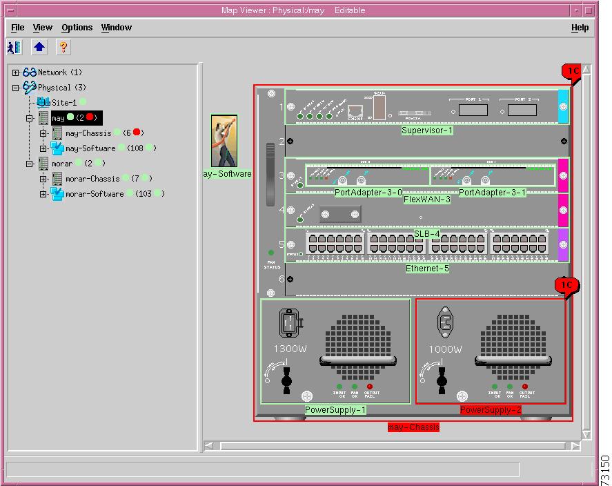
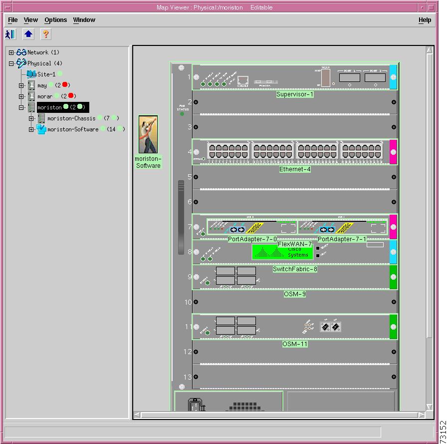
Figure 4-1 shows the CEMF Map Viewer application with the C65/76M software installed. When an object is deployed in CEMF, the objects are automatically added to the Network, Physical, and the appropriate Manager Views. In this example, the Network Element objects are called "may" and "morar," the Chassis objects are called "may-Chassis" and "morar-Chassis," and the Software objects are called "may-Software" and "morar-Software."
Under the Network container, the Network Element objects are labelled by their IP addresses and added to the group representing the subnet that they belong to (192.168.12.0). Under the Physical container, the Network Element and Chassis objects are available.
Note
Figure 4-1 Hierarchical Structure of Deployed and Commissioned Objects
Deployment and Commissioning Process
There are three methods that can be used to enable CEMF to monitor a Catalyst 6000 family switch or a Cisco 7600 series Internet Router:
•
This method should be used to deploy a large number of devices that are currently connected to the network. This method automatically deploys the Network Element and Software objects for each Catalyst 6000 family switch or Cisco 7600 series Internet Router discovered.
•
This method should be used if a small number of devices that are connected to the network need to be deployed. This method will deploy the Network Element and Software objects for the Catalyst 6000 family switches or Cisco 7600 series Internet Routers specified.
•
This method should be used to predeploy a device that is not connected to the network. The following objects can be predeployed:
–
–
–
–
–
–
–
–
The remaining C65/76M objects are automatically discovered when the Network Element object is commissioned.
IP Auto Discovery
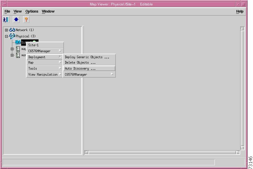
The CEMF Auto Discovery application is used to search an existing network. The network is examined for IP and SNMP devices. An object is created for each new device discovered. The IP discovery window can be launched from either the Discovery icon from the CEMF Launchpad (Figure 3-2) or from the Deployment/Auto Discovery... pop-up menu item on a selected object as shown in Figure 4-2.
Figure 4-2 Launching the IP Discovery Window from the Map Viewer
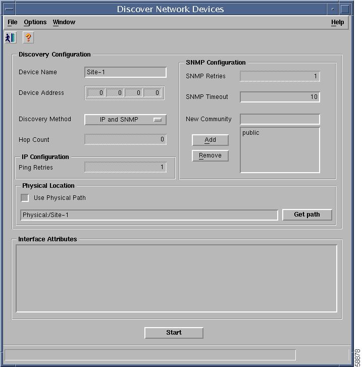
When first launched, the IP Discovery window will resemble Figure 4-3.
Figure 4-3 IP Discovery Window
The contents of this window depend on how the window was launched. For example, if this window was launched from an object in the physical containment view, then the Physical Location parameter would be automatically set to the location from which the window was launched, as shown in Figure 4-3. For more information on the CEMF Auto Discovery process, refer to the "Auto Discovery" chapter of the CEMF 3.1 Users Guide.
Note
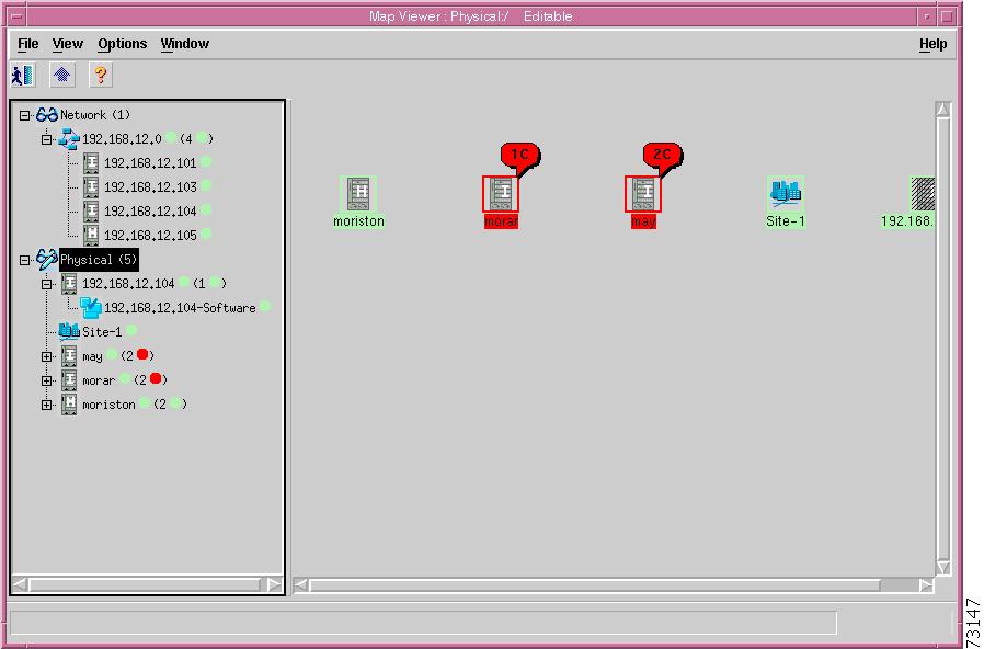
After the discovery process is complete, newly discovered objects will be automatically added to the Network containers and Physical containers. In the Network container, the object will be placed under the appropriate subnet. In the Physical container, discovered objects will be placed in the location based on the value of the Physical Location parameter.
If one of the discovered devices is a Catalyst 6000 family switch or a Cisco 7600 series Internet Router, then a C65/76M Network Element object will also be added into the Network containers, Physical containers, and the appropriate Manager Views. The Software object is also automatically added to the Manager View. In Figure 4-4, the Network Element object is labelled "192.168.12.105" and the Software object is labelled "192.168.12.105-Software."
Figure 4-4 Map Viewer with a Newly Discovered Catalyst 6500 Switch
After the Network Element and Software objects have been created by the Auto Discovery process, their contents need to be determined. This determination is made by commissioning the Network Element object. When the Network Element object is commissioned, it executes a subchassis discovery process that communicates with the switch to automatically determine the contents of the switch.
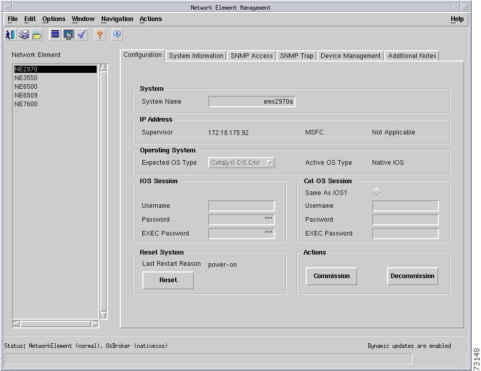
However, before the Network Element object can be commissioned, additional parameters are required. Specifically, the Telnet and Enable passwords and the SNMP communities are required. To specify the passwords and SNMP communities, right-click on the Network Element object (192.168.12.105 in Figure 4-4) and choose Open Network Element Dialog from the pop-up menu, which will launch a window that resembles Figure 4-5.
Figure 4-5 Network Element Dialog Box
When the dialog box is displayed, select the Configuration tab. In the CLI Passwords section, specify the Telnet Password and Enable Password parameters. The Telnet Password is the password used to connect to the switch using the Telnet protocol. The Enable Password is the password used to enter the enable mode on the switch or router. All values entered in these text fields will be displayed as "*".
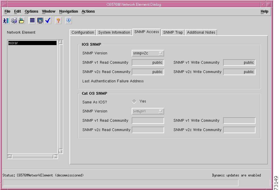
To specify the SNMP read and write community strings, select the SNMP tab and enter the correct SNMP read/write community strings.
Note
Figure 4-6 SNMP Tab in the Network Element Dialog Box
Click the Commission button from the Configuration tab (Figure 4-5) to start the subchassis discovery process, which allows the C65/76M to determine which modules are installed on the switch or the router and also allows CEMF to start monitoring the switch or the router.
Note
After the Network Element object is commissioned, the Physical view will resemble Figure 4-7.
Figure 4-7 Fully IP-Discovered and Commissioned Catalyst 6513 Switch
Manual Deployment
The manual deployment method is used when discovery of the entire network is not needed and the specific IP address and type of device that is connected to the network is known.
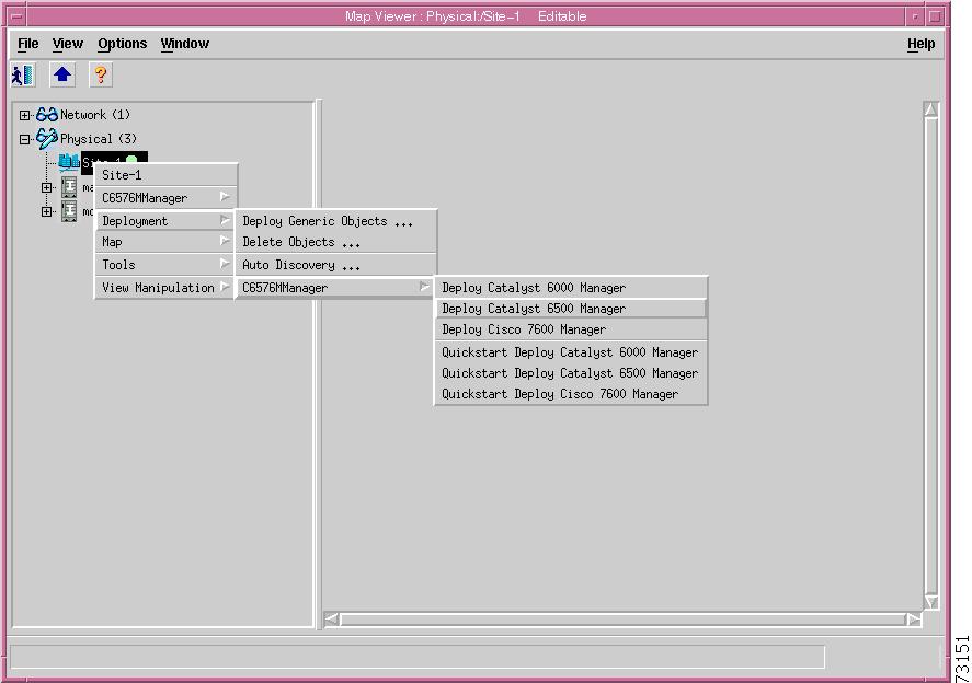
To manually deploy a Catalyst 6000 family switch or a Cisco 7600 series Internet Router, choose the pop-up menu item, Deployment >Deploy Manager, from the appropriate container. The following example describes how to manually deploy a Catalyst 6500 series switch. To manually deploy other devices, use the pop-up menu from the other manager containers.
Choose Deployment > Deploy Catalyst 6500 Manager from the pop-up menu. This pop-up menu item, shown in Figure 4-8, is available from the Site level in the Physical container and at the top level of the Catalyst6500Manager container.
Figure 4-8 Pop-up Menu for Manually Deploying a C65/76M Switch Object
When you select this item, the Deployment Wizard window shown in Figure 4-9 is displayed.
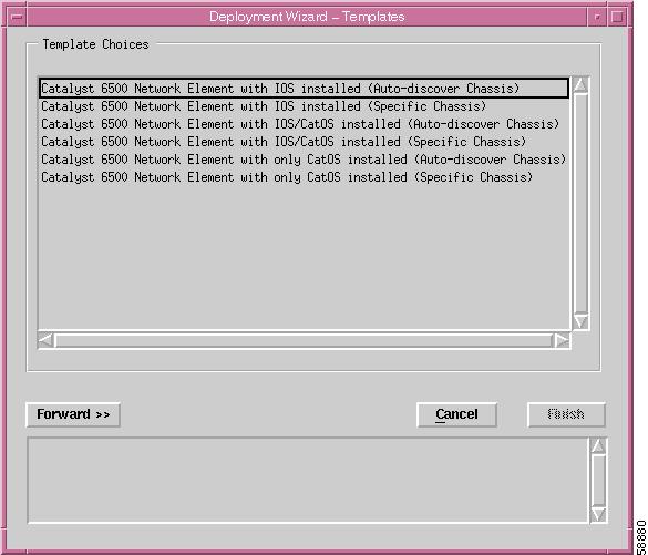
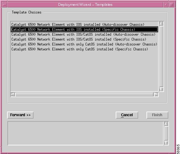
Figure 4-9 Deployment Wizard—Templates
Choose the Catalyst 6500 Switch Network Element Only option and click the Forward button. The Object Parameters window, shown in Figure 4-10, is displayed.
Tip
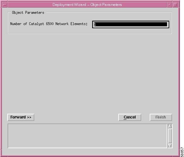
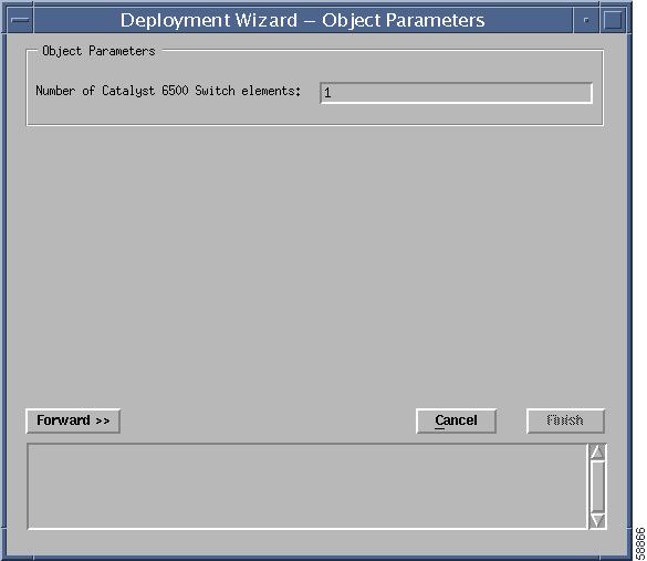
Figure 4-10 Deployment Wizard—Object Parameters
Number of Catalyst 6500 Switch elements
The number of switches or routers that you want to deploy at the same time.
Enter the number of Catalyst 6500 series switches or Cisco 7600 series Internet Routers that you want to deploy at the same time and click the Forward button. The remaining screens of this wizard are displayed for each switch or router to be deployed. The Object Parameters window, shown in Figure 4-11, is displayed.
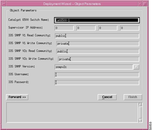
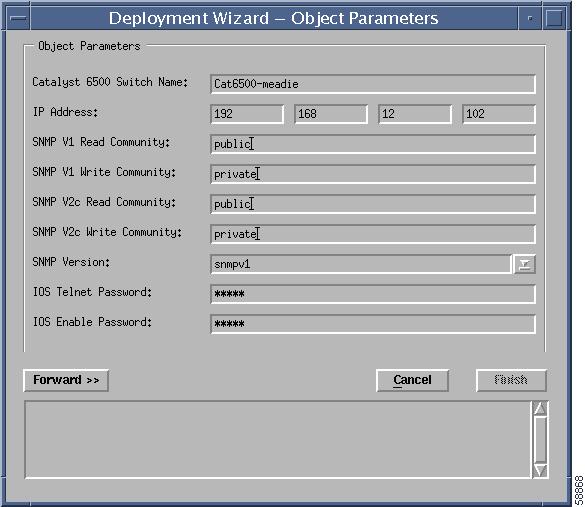
Figure 4-11 Deployment Wizard—Object Parameters Details
Enter the details for this window and then click the Forward button. The Views window, shown in Figure 4-12, may be displayed if the system requires a selection of the "location" of the network element within the physical hierarchy.
Note
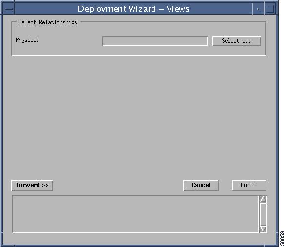
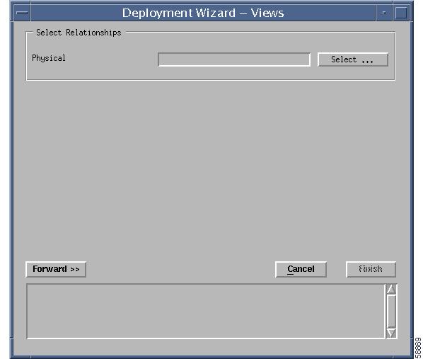
Figure 4-12 Deployment Wizard—Views
Physical
Location in the Physical containment view where the new object will be deployed.
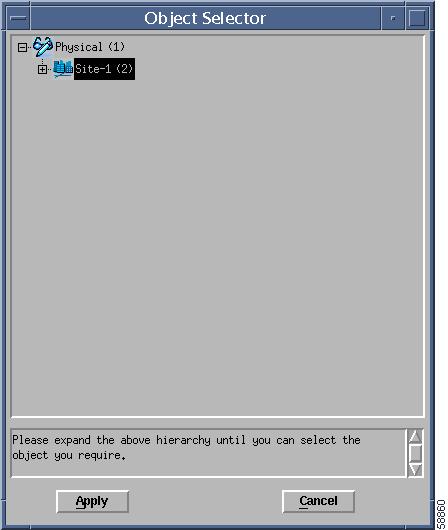
If the wizard was launched from a Site object in the Physical containment view, this screen will not be displayed, and the Physical parameter is set automatically. If this wizard is launched from any other containment view, this screen is displayed and you must specify the appropriate location in the Physical containment where the new object should be added. You can use the Select button to specify the Physical containment (Figure 4-13). Click the Forward button when completed.
Figure 4-13 Physical Containment Selection
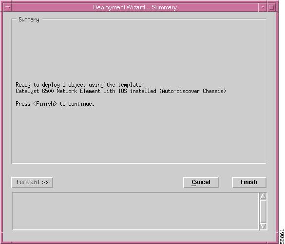
Choose the Physical containment view and then click Apply button. The Summary window, shown in Figure 4-14, is displayed.
Figure 4-14 Deployment Wizard—Summary
You can either cancel the operation by clicking Cancel or click Finish to create the object. If you click the Finish button, the Network Element and Software objects are added to the Map Viewer. The resulting Map Viewer resembles Figure 4-4.
After the Network Element and Software objects are created by the Deployment Wizard, the type of switch and its contents need to be determined. This determination is made by commissioning the Network Element object. When the Network Element object is commissioned, it executes a subchassis discovery process that communicates with the switch to automatically determine the contents of the switch.
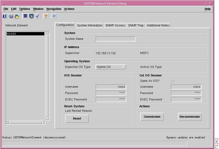
To commission the Network Element object, right-click on the Network Element object and choose Open Network Element Dialog from the pop-up menu, which launches a window that resembles Figure 4-15.
Figure 4-15 Network Element Dialog Box
Click the Commission button from the Configuration tab to start the subchassis discovery, which allows the C65/76M to determine which modules are installed on the switch or router, and also allows CEMF to start monitoring the switch or router.
Note
Unlike the Auto Discovery process (see the "IP Auto Discovery" section), no additional parameters need to be specified. These parameters were specified in the manual Deployment Wizard (Figure 4-11). After the object is commissioned, the Physical view will resemble Figure 4-16.
Figure 4-16 Manually Deployed and Commissioned Catalyst 6506 Switch
If an error is encountered when the object is commissioned, the Network Element object might go into the Mismatched or Lostcomms state and an alarm would be raised.
The Network Element is placed in the Mismatched state if the IP address specified during the deployment wizard does not correspond to the device type that was deployed. If this occurs, the Network Element object must be deleted from CEMF and redeployed with the correct IP address or type.
The Network Element is placed in the Lostcomms state if the SNMP read community string specified in during the deployment wizard is incorrect. If this occurs, open the Network Element dialog box, decommission the Network Element object, go to the SNMP tab (Figure 4-6) and enter the correct SNMP read community, and then recommission the Network Element object.
Predeployment
This deployment option is used to deploy the Catalyst 6000 family switch or Cisco 7600 series Internet Router into CEMF before it has been attached to the network. After an object has been predeployed, CEMF keeps the object in a decommissioned state until the device corresponding to the object is added to the network. After the switch is brought on-line, the predeployed object will be commissioned automatically. The following objects can be predeployed:
•
•
•
•
•
•
•
•
The remaining C65/76M objects are automatically discovered when the Network Element object is commissioned.
Network Element, Software, and Chassis Object Predeployment
To manually predeploy the Network Element, Software, and Chassis C65/76M objects, select the pop-up menu item, Deployment > Deploy Manager, from the appropriate container. The following example describes how to manually predeploy a Catalyst 6500 series switch. To manually predeploy other devices, use the pop-up menu from the other manager containers.
Choose Deployment > Deploy Catalyst 6500 Manager from the pop-up menu. This pop-up menu item, shown in Figure 4-17, is available from the Site level in the Physical container and at the top level of the Catalyst 6500 Manager container.
Figure 4-17 Manually Deploying a C65/76M Object
When you choose the Deployment > Deploy Catalyst 6500 Manager option, the Deployment Wizard—Templates window, shown in Figure 4-18, is displayed.
Figure 4-18 Deployment Wizard—Templates
Choose the Catalyst 6500 Switch Network Element and Chassis option and click the Forward button. The Object Parameters window, shown in Figure 4-19, is displayed.
Tip
Figure 4-19 Deployment Wizard—Object Parameters
Number of Catalyst 6500 Switch elements
The number of switches or routers that you want to predeploy at the same time.
Enter the number of Catalyst 6500 series switches or Cisco 7600 series Internet Routers that you want to predeploy at the same time and click the Forward button. The detailed Object Parameters window, shown in Figure 4-20, is displayed. The remaining screens in this wizard will be displayed for each switch or router to be predeployed.
Figure 4-20 Deployment Wizard—Object Parameters Details
Enter the details for the switch and then click the Forward button. The Views window may be displayed if the system requires a selection of the "location" of the network element within the physical hierarchy (see Figure 4-21).
Figure 4-21 Deployment Wizard—Views
Physical
Location in the Physical containment view where the new object will be deployed.
If this wizard was launched from a site in the Physical containment view, this screen will not be displayed. In this case, the Physical parameter is set automatically. If this wizard is launched from any other containment view, this screen is displayed and you must specify the appropriate location in the Physical containment view where the new object should be added. Click the Select button to select the Physical location parameter (see Figure 4-22). Click the Forward button when completed.
Figure 4-22 Physical Location Selection
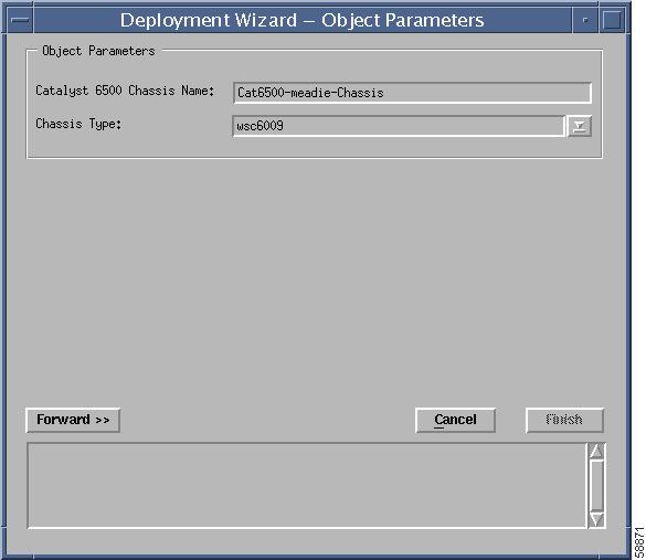
Click the Apply button when the Physical containment has been selected. The Object Parameters window, shown in Figure 4-23, is displayed.
Figure 4-23 Deployment Wizard—Object Parameters
Note
Note
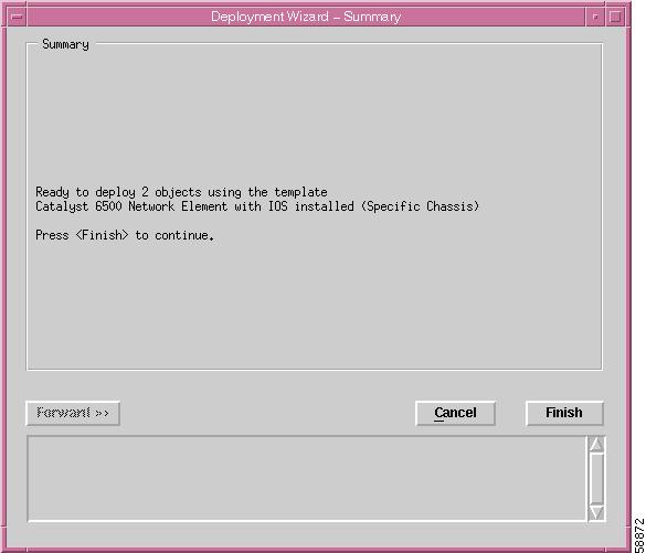
Specify the name of the Chassis object and the type of chassis to predeploy, and click the Forward button. The Summary window, shown in Figure 4-24, is displayed.
Figure 4-24 Deployment Wizard—Summary
You can either cancel the operation by clicking the Cancel button, or click the Finish button to create the object.
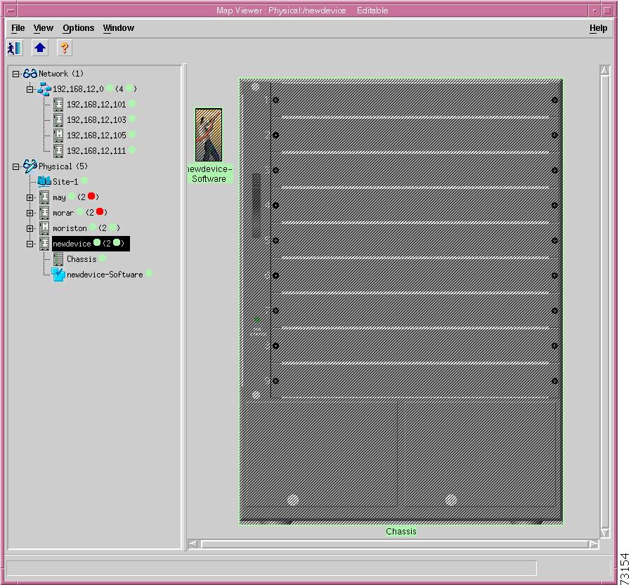
If you click the Finish button, the Network Element, Chassis, and Software objects are added to the Map Viewer. The chassis image that is displayed will depend on the value used for the Chassis Type. Figure 4-25 shows an example of a predeployed Catalyst 6509 chassis. Note that the chassis is empty and has cross hashes indicating that it is in the decommissioned state.
Figure 4-25 Predeployed Catalyst 6509 Chassis Object
Predeploying Subchassis Modules
The next step in predeploying a Catalyst 6000 family switch or a Cisco 7600 series Internet Router in CEMF is to deploy the modules within the chassis. The following subchassis objects can be predeployed:
•
•
•
•
•
•
•
Tip
Supervisor Module
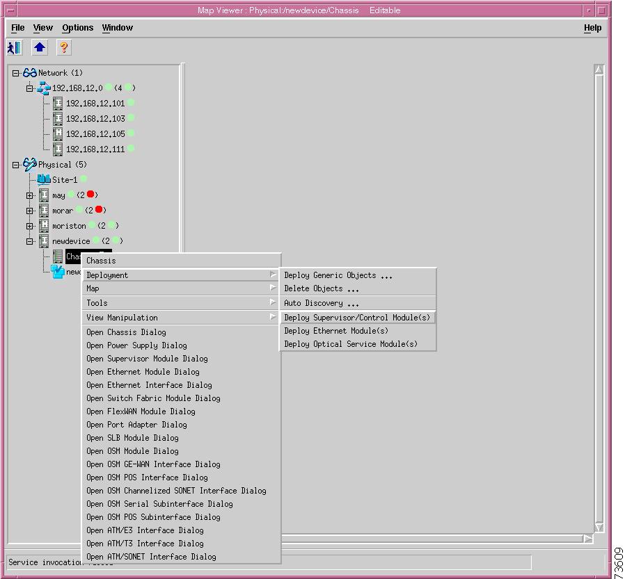
To predeploy a Supervisor Module, choose Deployment > Deploy Supervisor/Control Modules(s)from the pop-up menu of the Chassis object (see Figure 4-26).
Figure 4-26 Predeploying Supervisor Modules
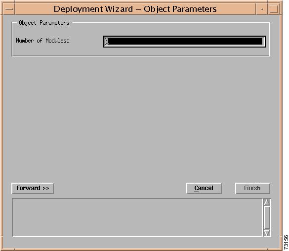
The Supervisor Module Deployment Wizard—Object Parameters window, as shown in Figure 4-27, is displayed.
Figure 4-27 Supervisor Module Deployment Wizard—Object Parameters
Enter the number of supervisor modules to predeploy and click the Forward button. The Supervisor Module Deployment Wizard—Object Parameters Details window is displayed for each module to deploy (see Figure 4-28).
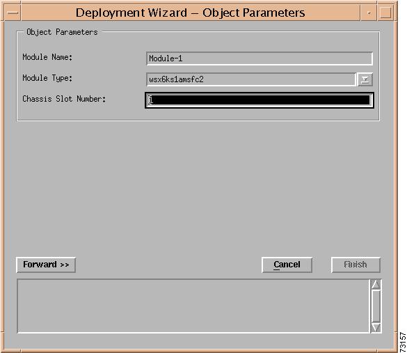
Figure 4-28 Supervisor Module Deployment Wizard—Object Parameters Details
Note
Note
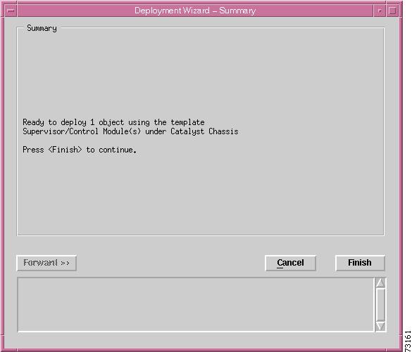
Enter the details for the Supervisor Module object and click the Forward button. The Supervisor Module Deployment Wizard—Summary window is displayed (see Figure 4-29).
Figure 4-29 Supervisor Module Deployment Wizard—Summary
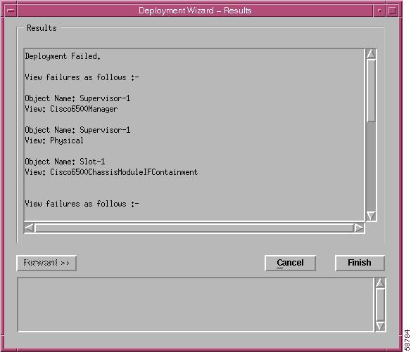
You can either click the Cancel button to cancel the operation, or click the Finish button to create the object. If the Chassis Slot Number corresponds to an occupied slot, an error message will be displayed. The error message resembles the message shown in Figure 4-30.
Figure 4-30 Predeployment Failure Due to an Occupied Slot
Ethernet Module
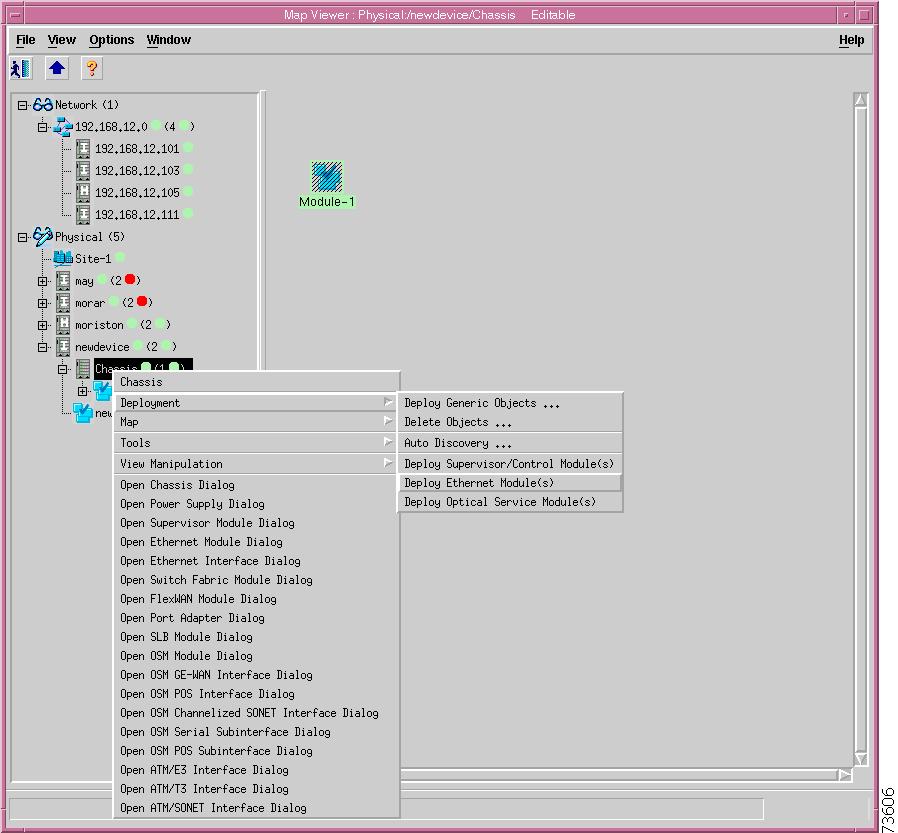
To predeploy an Ethernet module (standard Ethernet, Fast Ethernet, or Gigabit Ethernet), choose the Deployment > Deploy Ethernet Module(s) option from the pop-up menu of the Chassis object (see Figure 4-31).
Figure 4-31 Predeploying Ethernet Modules
After you choose the Deploy Ethernet Module option, the window shown in Figure 4-32 is displayed.
Figure 4-32 Ethernet Module Deployment Wizard—Object Parameters
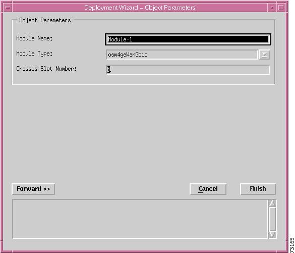
Enter the number of Ethernet module objects to be predeployed at the same time and click the Forward button. The window shown in Figure 4-33 is displayed.
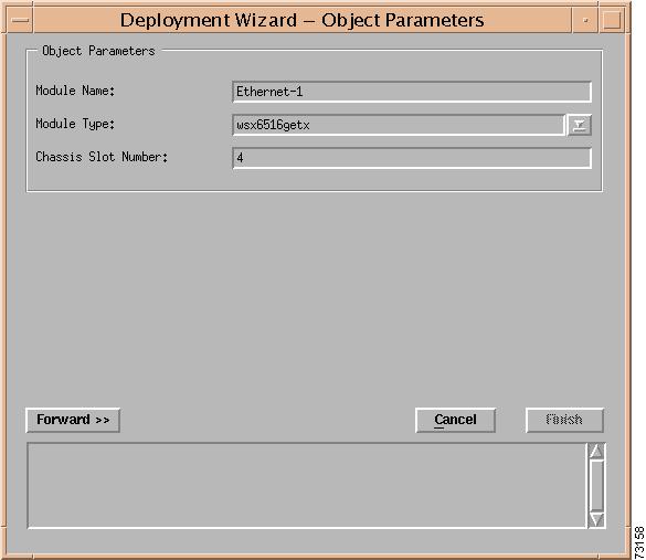
Figure 4-33 Ethernet Module Deployment Wizard—Object Parameters Details
Enter the details for the Ethernet Module object and click the Forward button. The Ethernet Module Deployment Wizard—Summary window is displayed (see Figure 4-34).
Figure 4-34 Ethernet Module Deployment Wizard—Summary
You can either click the Cancel button to cancel the operation or click the Finish button to create the object. If the Chassis Slot Number corresponds to an occupied slot, an error message is displayed. The error message resembles the message shown in Figure 4-30.
Switch Fabric Module
To predeploy a Switch Fabric Module, choose the Deployment > Deploy Supervisor/Control Module(s) option in the pop-up menu from the Chassis object (see Figure 4-35).
Figure 4-35 Predeploying Switch Fabric Modules
After you choose the Deploy Switch Fabric Module(s) option, the Switch Fabric Module Deployment Wizard—Object Parameters window is displayed (see Figure 4-36).
Figure 4-36 Switch Fabric Module Deployment Wizard—Object Parameters
Number of Modules
The number of Switch Fabric Modules to deploy at the same time.
Enter the number of Switch Fabric Modules to be deployed at the same time and click the Forward button. The Switch Fabric Module Deployment Wizard—Object Parameters Details window is displayed for each module to deploy (see Figure 4-37).
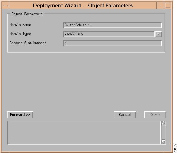
Figure 4-37 Switch Fabric Module Deployment Wizard—Object Parameters Details
Enter the details for the Switch Fabric Module object and click the Forward button. The Switch Fabric Module Deployment Wizard—Summary window is displayed (see Figure 4-38).
Figure 4-38 Switch Fabric Module Deployment Wizard—Summary
You can either click the Cancel button to cancel the operation or click the Finish button to create the object. If the Chassis Slot Number corresponds to an occupied slot, an error message is displayed. The error message resembles the message shown in Figure 4-30.
FlexWAN Module
To predeploy a FlexWAN Module, choose the Deployment > Deploy Supervisor/Control Module(s) option in the pop-up menu from the Chassis object (see Figure 4-39).
Figure 4-39 Predeploying FlexWAN Modules
After you choose the Deploy FlexWAN Module(s) option, the FlexWAN Module Deployment Wizard—Object Parameters window is displayed (see Figure 4-40).
Figure 4-40 FlexWAN Module Deployment Wizard—Object Parameters
Number of Modules
The number of FlexWAN modules to be deployed at the same time. This value cannot be greater than 12.
Enter the number of FlexWAN modules to be deployed at the same time and click Forward button. The FlexWAN Module Deployment Wizard - Object Parameters Details window is displayed for each module to be deployed (see Figure 4-41).
Note
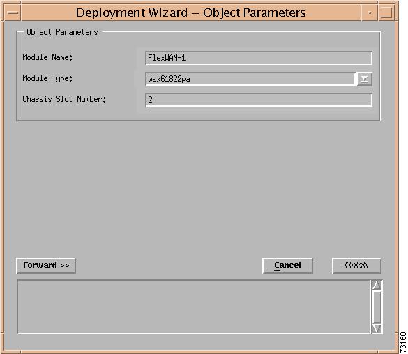
Figure 4-41 FlexWAN Module Deployment Wizard—Object Parameters Details
Enter the details for the FlexWAN Module object and click the Forward button. The FlexWAN Module Deployment Wizard—Summary window is displayed (see Figure 4-42).
Figure 4-42 FlexWAN Module Deployment Wizard—Summary
You can either click the Cancel button to cancel the operation or click the Finish button to create the object. If the Chassis slot number corresponds to an occupied slot, an error message is displayed. The message resembles the message shown in Figure 4-30.
Port Adapters
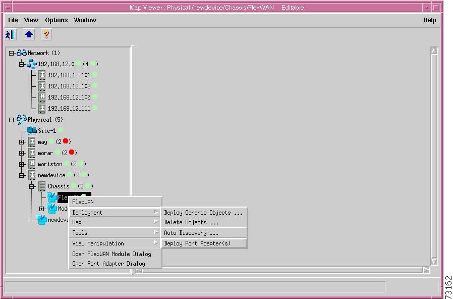
To predeploy a port adapter, the FlexWAN module must first be deployed (see the "FlexWAN Module" section). Choose the Deployment > Deploy Port Adapter(s) option in the pop-up menu from the FlexWAN object (see Figure 4-43).
Figure 4-43 Predeploying Port Adapters
The Port Adapter Deployment Wizard—Object Parameters window is displayed (see Figure 4-44).
Figure 4-44 Port Adapter Deployment Wizard—Object Parameters
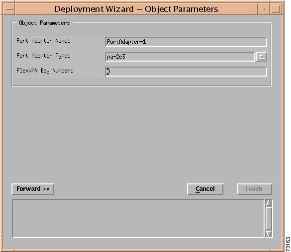
Enter the number of port adapters to be deployed at the same time and click Forward button. The Port Adapter Deployment Wizard - Object Parameters Details window is displayed for each module to be deployed (see Figure 4-45).
Note
Figure 4-45 Port Adapter Deployment Wizard—Object Parameters Details
Note
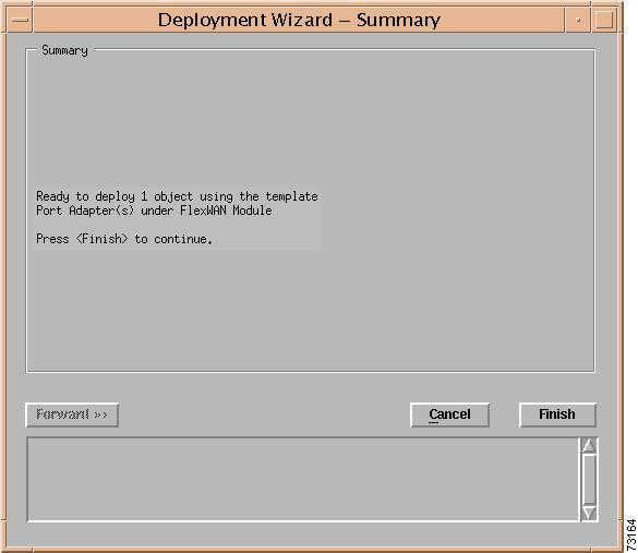
Enter the details for the Port Adapter object and click the Forward button. The Port Adapter Deployment Wizard—Summary window is displayed (see Figure 4-46).
Figure 4-46 Port Adapter Deployment Wizard—Summary
You can either click the Cancel button to cancel the operation or click the Finish button to create the object. If the Chassis slot number corresponds to an occupied slot, an error message is displayed. The message resembles the message shown in Figure 4-30.
Content Switching Module
The Content Switching Module is a line card that provides server load balancing (SLB) of client traffic to server farms, firewalls, secure sockets layer (SSL) devices, or VPN termination devices. To predeploy a Content Switching Module (CSM), choose the Deployment > Deploy Supervisor/Control Module(s) option in the pop-up menu from the Chassis object (see Figure 4-47).
Figure 4-47 Predeploying Content Switching Modules
After you choose the Deploy Supervisor/Control Module(s) option, the Deployment Wizard—Object Parameters window is displayed (see Figure 4-48).
Figure 4-48 Deployment Wizard—Object Parameters
Enter the number of Content Switching Modules to be deployed at the same time and click Forward button. The Deployment Wizard—Object Parameters Details window is displayed for each module to be deployed (see Figure 4-49).
Note
Caution
Figure 4-49 Deployment Wizard—Object Parameters Details
Enter the details for the Content Switching Module object and click the Forward button. The Deployment Wizard—Summary window is displayed (see Figure 4-50).
Figure 4-50 Deployment Wizard—Summary
You can either click the Cancel button to cancel the operation or click the Finish button to create the object. If the Chassis slot number corresponds to an occupied slot, an error message is displayed. The message resembles the message shown in Figure 4-30.
Optical Services Module
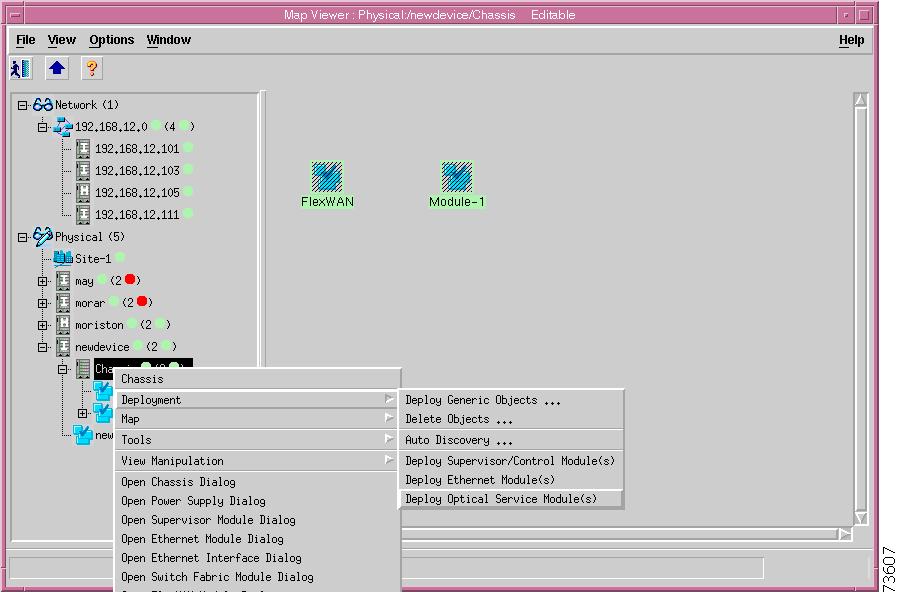
To predeploy an Optical Services Module (OSM), choose the Deploy Module(s), Deploy OSM Module option in the pop-up menu from the Chassis object (see Figure 4-51).
Figure 4-51 Predeploying OSM Modules
After you choose the Deploy OSM Module(s) option, the OSM Module Deployment Wizard—Object Parameters window is displayed (see Figure 4-52).
Figure 4-52 OSM Module Deployment Wizard—Object Parameters
Enter the number of OSMs to be deployed at the same time and click Forward button. The Deployment Wizard—Object Parameters Details window is displayed for each module to be deployed (see Figure 4-53).
Figure 4-53 OSM Module Deployment Wizard—Object Parameters Details
Enter the details for the OSM object and click the Forward button. The Deployment Wizard—Summary window is displayed (see Figure 4-54).
Figure 4-54 OSM Deployment Wizard—Summary
You can either click the Cancel button to cancel the operation or click the Finish button to create the object. If the Chassis slot number corresponds to an occupied slot, an error message is displayed. The message resembles the message shown in Figure 4-30.
Commissioning Predeployed Objects
A predeployed Network Element and subobjects are commissioned automatically when a coldStart SNMP trap that is issued from the switch or the router is received by the CEMF server.
Note
The subchassis discovery task is executed during commissioning. The discovery task does the following:
•
•
•
•
If the coldStart trap is not received by the CEMF server when the switch is first brought on-line, then the predeployed Network Element object needs to be commissioned manually by opening the Network Element dialog box and selecting the Commission button (see Figure 4-15).