-
Cisco IOS Voice, Video, and Fax Configuration Guide, Release 12.2
-
About Cisco IOS Software Documentation
-
Using Cisco IOS Software
-
Voice, Video, and Fax Overview
-
Cisco Voice Telephony
-
Voice over IP Overview
-
Configuring Voice Ports
-
Configuring Dial Plans, Dial Peers, and Digit Manipulation
-
Configuring Quality of Service for Voice
-
H.323 Applications
-
Configuring H.323 Gateways
-
Configuring H.323 Gatekeepers
-
Configuring MGCP and Related Protocols
-
Configuring SIP for VoIP
-
Configuring Voice over Frame Relay
-
Configuring Voice over ATM
-
Configuring Tcl IVR Applications
-
Configuring Debit Card Applications
-
Configuring Settlement Applications
-
Configuring Trunk Connections and Conditioning Features
-
Configuring ISDN Interfaces for Voice
-
Configuring PBX Interconnectivity Features
-
Configuring Fax Applications
-
Configuring Modem Support for VoIP
-
Configuring Video Applications
-
Appendixes
-
Appendix A - Configuring Synchronized Clocking
-
Appendix B - Caller ID
-
Appendix C-Cisco Hoot and Holler over IP
-
Appendix D - Managing Cisco AS5300 Voice Feature Cards
-
Appendix E - Enhanced Voice Services for Japan for Cisco 800 Series Routers
-
Appendix F-Global System for Mobile Communications Full Rate and Enhanced Full Rate Codecs
-
Appendix G - Configuring the Cisco SS7/C7 Dial Access Solution System
-
-
 Feedback
Table Of Contents
Configuring Voice over Frame Relay
End-to-End FRF.12 Fragmentation
Frame Relay Fragmentation Using FRF.11 Annex C
Cisco Proprietary Voice Encapsulation
Map Classes and Voice Packet Queues
Configuring Frame Relay to Support Voice
Configuring a Map Class to Support Voice Traffic
Configuring a Map Class for Traffic-Shaping Parameters
Tandem Switching of Switched Calls
Configuring FRF.11 Trunk Calls
Verifying the Voice Connections
Verifying the Frame Relay Configuration
Monitoring and Maintaining the VoFR Configuration
Two Routers Using Frame Relay Fragmentation Example
Two Routers Using a VoFR PVC Example
Router Using VoFR PVCs Connected to Cisco MC3810s Before 12.1(2)T Example
Cisco Trunk Calls Between Two Routers Example
FRF.11 Trunk Calls Between Two Routers Example
Cisco Trunk Call with Hunt Groups Example
Configuring Voice over Frame Relay
This chapter describes the configuration of Voice over Frame Relay (VoFR) and contains the following sections:
For a description of the VoFR configuration commands using the FRF.11 implementation agreement, refer to the Cisco IOS Voice, Video, and Fax Command Reference. For additional information about the FRF.12 implementation agreement and wide-area networks (WANs), refer to the Cisco IOS Wide-Area Networking Configuration Guide and Cisco IOS Wide-Area Networking Command Reference. For information about voice port configurations, refer to the "Configuring Voice Ports" chapter.
To identify the hardware platform or software image information associated with a feature in this chapter, use the Feature Navigator on Cisco.com to search for information about the feature or refer to the software release notes for a specific release. For more information, see the "Identifying Supported Platforms" in the "Using Cisco IOS Software" chapter.
VoFR Overview
VoFR enables a router to carry voice traffic (for example, telephone calls and faxes) over a Frame Relay network, using the FRF.11 protocol. This specification defines multiplexed data, voice, fax, dual tone multi frequency (DTMF) digit-relay, and channel-associated signaling (CAS)/robbed-bit signaling frame formats. The Frame Relay backbone must be configured to include the map class and Local Management Interface (LMI).
The Cisco VoFR implementation enables dynamic- and tandem-switched calls and Cisco trunk calls. Dynamic-switched calls have dial-plan information included that processes and routes calls based on the telephone numbers. The dial-plan information is contained within dial-peer entries. For more information, see "Switched Calls" section.
Tandem-switched calls are switched from incoming VoFR to an outgoing VoFR enabled data-link connection identifier (DLCI) and tandem nodes enable the process. The nodes also switch Cisco trunk calls.
Permanent calls are processed over Cisco private-line trunks and static FRF.11 trunks that specify the frame format and coder types for voice traffic over a Frame Relay network. For more information, see "Permanent Calls" section.
VoFR connections depend on the hardware platform and type of call. The types of calls are:
•
Switched (user dialed or auto-ringdown and tandem)
•
Note
VoFR Dial Peers
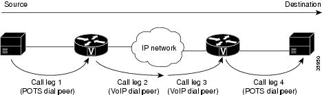
Dial peers are addressable call endpoints that identify the origin and destination of a call. Dial peers define the characteristics applied to each call leg in the call connection. A call leg is a logical connection between two routers or between a router and a telephony device.
A traditional voice call over the Public Switched Telephone Network (PSTN) uses a dedicated 64K circuit end-to-end. In contrast, a voice call over the packet network is made up of call legs. A voice call has four call legs, two from the perspective of the originating router and two from the perspective of the destination router, as shown in Figure 74.
Figure 74 Dial Peer Call Legs
A dial peer is associated with each call leg. Attributes that are defined in a dial peer and applied to the call leg include codec, Quality of Service (QoS), voice activity detection (VAD), and fax rate. To complete a voice call, you must configure a dial peer for each of the four call legs in the call connection.
Two kinds of dial peers are possible in VoFR configurations:
•
•
VoFR peers point to specific voice-network devices by associating destination telephone numbers with a specific Frame Relay DLCI so that outgoing calls can be placed. Both POTS and VoFR dial peers are needed to establish VoFR connections if the sending and receiving of calls are required.
Understanding the the relationship between the destination pattern and the session target is critical to understanding VoFR dial peers. The destination pattern is the telephone number of the voice device attached to the voice port. The session target defines the route to a serial port on the peer router at the other end of the Frame Relay connection.
Note
For additional information on POTS dial peers, see the "Configuring Dial Plans, Dial Peers, and Digit Manipulation" chapter.
Switched Calls
The Cisco-switched VoFR protocol handles call setup and parameter negotiation for both endpoints and intermediate nodes within the multihop call path. The call setup mechanism originally implemented in the Cisco MC3810 multiservice concentrator can be used for permanent-switched (Cisco trunk) or dynamic-switched calls. The Cisco VoFR protocol includes forwarding of the called telephone number and supports tandem switching of the call over multiple Frame Relay permanent virtual connection (PVC) hops.
Cisco addresses the lack of end-to-end call parameter negotiation and call setup syntax in FRF.11 by implementing a proprietary Q.931-like session protocol running on a user-configurable channel ID (CID) of an FRF.11-format multiplexed DLCI.
Tandem Switching
Dynamic switching of voice calls between VoFR or VoATM PVCs and subchannels is also called tandem switching (often encountered in multihop VoFR call connection paths). Tandem switching uses nodes that are intermediate router nodes within the Frame Relay call path.
Each node switches the frames from one PVC subchannel to another (from one VoFR dial peer to another VoFR dial peer) as the frames traverse the network. Use of tandem router nodes avoids the need to have complete dial-plan information present on every router.
Dynamic-Switched Calls
Dynamic-switched calls are regular telephone calls in which the switching is performed by the Cisco router. The destination endpoint of the call is selected by the router based on the dialed telephone number and the dial peer configuration entries. This implementation is different from permanent calls (Cisco trunk calls) in which the call endpoints are permanently fixed at configuration time. The dial peer uses the Cisco proprietary session protocol.
Cisco Trunk Calls
A Cisco trunk call is a dynamic-switched call of indefinite duration that uses a fixed-destination telephone number and includes optional transparent end-to-end signaling. The telephone number of the destination endpoint is permanently configured into the router so that it always selects a fixed destination. Once established, at boot-up or when configured, the call stays up until one of the voice ports or network ports is shut down or until a network disruption occurs. The dial peer is configured to invoke the Cisco proprietary session protocol.
Permanent Calls
Permanent calls are transmitted and received on FRF.11 and Cisco trunks. FRF.11 trunk interoperability for standards-based vendors enables specification of the frame format and coder types to be used when sending voice traffic through a Frame Relay network. However, FRF.11 does not have specifications for end-to-end negotiation, call setup process, or any other form of communication between the Frame Relay nodes.
As a result, static FRF.11 trunks are set up by manually configuring each router within the voice trunk path with compatible parameters: a voice port and a specific subchannel on a DLCI are explicitly bound on each end router. Signaling information is packed and sent transparently end-to-end.
The two ends of an FRF.11 call must use the same compatible speech compression codecs. If not, the call exists and voice packets are sent and received, but no usable voice path is created.
When configured, a static FRF.11 trunk remains up until the voice or serial port is shut down or until a network disruption occurs. The FRF.11 specification does not include any standardized methods for performing Operation, Administration, and Maintenance (OAM) functions. There is no standard protocol for detecting faults and providing rerouting of connection paths.
FRF.11 enables up to 255 subchannels to be multiplexed onto a single Frame Relay DLCI. The current implementation supports the multiplexing of a single data channel with many voice channels. However, subchannels from zero to three are reserved and cannot be configured for voice or data.
Frame Relay Fragmentation
Cisco has developed three methods of performing Frame Relay fragmentation that are described in the following sections:
•
•
•
FRF.11 can only be used when an end-to-end PVC is available between the voice ports at each end of the connection. At intermediate Frame Relay nodes, the entire PVC must be routed. Because the entire PVC is routed, no prioritization of voice packets is possible at the intermediate Frame Relay. Connection ID-based routing (individual channel-ID switching) is not supported.
FRF.11 specifies that a device can pack multiple FRF.11 subframes within a single Frame Relay frame; however, the Cisco implementation of VoFR currently does not support multiple subframes within a frame. VoFR frames are never fragmented, regardless of size. If fragments arrive out of sequence, packets are dropped. Fragmentation is performed after frames are removed from the weighted fair queuing (WFQ). WFQ at the PVC level is the only queueing strategy that can be used.
Frame Relay Traffic Shaping (FRTS) must be configured to enable Frame Relay fragmentation.
Frame Relay fragmentation can be configured in conjunction with VoFR or independently of it. For additional information regarding FRF.12 fragmentation and the implementation commands, refer to the Cisco IOS Wide-Area Networking Configuration Guide and Cisco IOS Wide-Area Networking Command Reference.
VoFR provides support for various FRF.11 features depending on the hardware platform used (see Table 27).
End-to-End FRF.12 Fragmentation
FRF.12 fragmentation is defined by the FRF.12 standard. The FRF.12 implementation agreement enables long data frames to be fragmented into smaller pieces and interleaved with real-time frames. In this way, real-time voice and nonreal-time data frames can be carried together on lower-speed links without causing excessive delay to the real-time traffic.
Use this fragmentation type when the PVC is not carrying voice, but is sharing the link with other PVCs that are carrying voice. The fragmentation header is included only for frames that are greater than the fragment size configured. FRF.12 is the recommended fragmentation for VoIP packets.
Note
The Cisco 2600 series, 3600 series, and 7200 series routers and the Cisco MC3810 multiservice concentrator support end-to-end fragmentation on a per-PVC basis. Fragmentation is configured through a map class that applies to one or many PVCs, depending on how the class is applied.
When end-to-end FRF.12 fragmentation is used, the VoIP packets do not include the FRF.12 header, provided the size of the VoIP packet is smaller than the fragment size configured. However, when FRF.11 Annex C or Cisco proprietary fragmentations are used, VoIP packets do include the fragmentation header.
Frame Relay Fragmentation Using FRF.11 Annex C
When VoFR and fragmentation are configured on a PVC, the Frame Relay fragments are sent in the FRF.11 Annex C format. FRF.11 fragmentation is used when voice traffic is sent on the PVC, and Annex C format is used for data. With FRF.11, all data packets contain fragmentation headers, regardless of size. This form of fragmentation is not recommended for use with VoIP.
Cisco Proprietary Voice Encapsulation
Cisco proprietary voice encapsulation was implemented for the Cisco MC3810 multiservice concentrator and was used for data packets on a PVC and voice traffic. This fragmentation type is used on data packets on PVCs that carry voice traffic.
When VoFR is configured on a DLCI and fragmentation is enabled on a map class, the Cisco 7500 series router with Versatile Interface Processor (VIP) can interoperate with Cisco 2600 series, 3600 series, 7200 series, and other 7500 series routers as tandem nodes, but it cannot perform call termination with Cisco MC3810 multiservice concentrators running Cisco IOS releases before 12.0(3)XG or 12.0(4)T.
Map Classes and Voice Packet Queues
You must create and configure a Frame Relay map class before configuring a Frame Relay DLCI for voice traffic. The map class has configuration information about voice bandwidth, fragmentation size, and traffic shaping attributes. These attributes are required for sending voice traffic on the PVC.
Traffic Shaping
When a Frame Relay PVC is configured to support voice traffic, the carrier must be able to accommodate the traffic rate or profile sent on the PVC. If too much traffic is sent at once, the carrier might discard frames causing disruptions to real-time voice traffic. The carrier might also deal with traffic bursts by queueing up the bursts and delivering them at a metered rate. Excessive queueing also causes disruption to real-time voice traffic. Traffic shaping compensates for this condition and is necessary to prevent the carrier from discarding eligible discard bits on ingress and to prevent excessive burst data from affecting voice quality.
When the outgoing Excess Burst (Be) size is configured, the Committed Burst (Bc) size and the committed information rate (CIR) values must be obtained from the carrier. The configured values on the router must match those of the carrier.
VoFR Prerequisite Tasks
Before configuring the router for VoFR, perform the following tasks:
•
–
–
•
•
•
•
VoFR Configuration Task List
This section describes the following tasks:
•
•
For information regarding the configuring of voice ports and dial peers, refer to the "Configuring Voice Ports" and "Configuring Voice Dial Peers, Dial Plans, and Digit Manipulation" chapters.
Configuring Frame Relay to Support Voice
To configure Frame Relay to support voice, a map class must be applied to a single DLCI or to a group of DLCIs, depending on how the class has been applied to the virtual circuit. If there is a large number of PVCs to configure, assign the same traffic-shaping properties to the PVCs. The values for each PVC are not statically defined. Multiple map classes with different variables for each map class can also be created.
When the frame-relay voice bandwidth command is entered, a special queue is created for voice packets only so that time-sensitive voice packets have preference over data packets.
This section describes the configuration of map classes as follows:
•
•
To configure the map class to support FRF.12 fragmentation, refer to the Cisco IOS Wide-Area Networking Configuration Guide and Command Reference for more information.
Configuring a Map Class to Support Voice Traffic
When you are configuring a Frame Relay map class to support voice traffic, you must reserve the appropriate amount of voice bandwidth. If there is not enough bandwidth reserved, new calls are rejected. When calculating the amount of required voice bandwidth, include the voice packetization overhead and not just the raw compressed speech codec bandwidth.
Remember that there are a six or seven bytes of total overhead per voice packet, including standard Frame Relay headers and flags. For subchannels (CIDs) numbered less than 64, the overhead is 6 bytes. For subchannels numbered greater than or equal to 64, the overhead is 7 bytes. Add one byte if voice sequence numbers are enabled in the voice packets.
To determine the required voice bandwidth, use the following calculation:
required_bandwidth = codec_bandwidth * (1 + overhead/payload_size)
This calculation addresses the amount of bandwidth consumed on the physical network interface. The figure does not necessarily represent the amount of connection bandwidth used within the Frame Relay network itself, which may be higher because the overhead of switching small packets.
When 30-ms duration voice packets are used, an approximate general rule is to add 2000 bps overhead to the raw voice compressed speech codec rate. With the 32 kbps G.726 adaptive differential pulse code modulation (ADPCM) speech coder, a 30-ms speech frame uses 120 bytes voice payload plus 6 to 7 bytes overhead, and the overall bandwidth requirement is about 34 kbps for each call.
To configure a Frame Relay map class to support voice traffic on DLCIs, use the following commands beginning in global configuration mode:
Note
Configuring a Map Class for Traffic-Shaping Parameters
To configure a Frame Relay map class for the traffic shaping parameters for one or more DLCIs, use the following commands in map-class configuration mode:
Configuring VoFR Dial Peers
To configure a VoFR dial peer, you must uniquely identify the peer (by assigning it a unique tag number) and define the outgoing serial port number and the virtual circuit number.
Depending on your dial plan configuration, you might need to consider how to configure voice networks with variable-length dial plans, number expansion, excess digit playout, forward digits, and default voice routes, or use hunt groups with dial peer preferences.
Note
To configure a VoFR dial peer, use the following commands beginning in global configuration mode:
To configure another VoFR dial peer, exit dial peer configuration mode and repeat Steps 1 through 10.
Note
Configuring Switched Calls
To configure switched calls on Cisco 2600, 3600, and 7200 series routers and Cisco MC3810 multiservice concentrators, use the following commands beginning in interface configuration mode:
Table 28 lists the supported VoFR connections and the appropriate commands to configure switched calls.
Table 28 Supported VoFR Connections for Switched Calls
(User-Dialed or Auto-Dialed)To routers supporting VoFR
FRF.11 Annex C
vofr [data cid] [call-control [cid]]3
session protocol cisco-switched4
For user-dialed calls: none
For auto-ringdown calls:
connection plar destination-stringTo a Cisco MC3810 multiservice concentrator running Cisco IOS Releases before 12.1(2)T
Cisco proprietary5
vofr cisco6
session protocol cisco-switched
For user-dialed calls: none
For auto-ringdown calls:
connection plar destination-string
1 The voice-encap option of the frame-relay interface-dlci command on the Cisco MC3810 multiservice concentrator is no longer supported.
2 Dial peer configuration mode.
3 The recommended use of this command is vofr data 4 call-control 5.
4 The session protocol cisco-switched command is the default setting. If the command is not entered, the setting still applies.
5 Cisco proprietary fragmentation is based on an early draft of FRF.12 and is compatible with Cisco MC3810 multiservice concentrators.
6 This command uses data CID 4 and call-control CID 5.
Tandem Switching of Switched Calls
Depending on which router is the end node and which is the tandem node, the correct Frame Relay PVC type must be configured. Table 29 shows the router combinations that can serve as end and tandem nodes and the command that is required to enable VoFR.
Note
To configure VoFR dial peers on tandem routers, use the following commands beginning in global configuration mode:
To configure the next VoFR dial peer, exit dial peer configuration mode by entering exit, and repeat Steps 1 through 4. On tandem nodes, at least two VoFR dial peers are required, one for each call leg.
Configuring Cisco Trunk Calls
Before configuring the Cisco trunk calls, consider the following restrictions and recommendations:
•
•
•
Table 30 lists the supported VoFR connections and the commands to enter.
Table 30 VoFR Connections for Cisco Trunk Calls
CommandTo routers supporting VoFR
FRF.11 Annex C
vofr data cid call-control cid
session protocol cisco-switched
connection trunk destination-string [answer mode]
To a Cisco MC3810 multiservice concentrator running Cisco IOS Releases before 12.0(7) XK and 12.1(2)T
Cisco proprietary
vofr cisco2
session protocol cisco-switched
connection trunk destination-string [answer mode]
1 The session protocol cisco-switched command, whether entered or not, is the default setting.
2 When the cisco keyword is entered, Cisco proprietary data implementation is enabled. This implementation is used only for backward compatibility to earlier releases.
To configure Cisco trunk permanent calls, use the following commands beginning in interface configuration mode:
Note
Configuring FRF.11 Trunk Calls
On the Cisco MC3810 multiservice concentrators and Cisco 2600 and 3600 series routers, FRF.11 trunk calls to a second router can be configured, except tandem FRF.11 trunk calls. Configuring FRF.11 trunk calls to a second router requires that the session protocol dial peer configuration command be set to frf11-trunk.
Table 31 lists the supported VoFR connections and the required commands to configure FRF.11 trunk calls.
Table 31 VoFR Connections for FRF.11 Trunk (Private-Line) Calls
DLCI Command1
CommandTo routers supporting VoFR
FRF.11 Annex C
vofr [data cid] [call-control cid]2
session protocol frf11-trunk
connection trunk destination-string [answer mode]
1 Dial peer configuration mode.
2 For FRF.11 trunk calls, the call-control option is not required. It is required only if you mix FRF.11 trunk calls with other types of voice calls on the same PVC.
To configure FRF.11 trunk calls, use the following commands beginning in interface configuration mode:
Note
Verifying the Voice Connections
To verify switched calls voice connections, perform the following tasks:
•
•
To verify the FXO-FXS trunk calls to a remote PBX, perform the following tasks:
•
•
To verify the voice connections, perform the following tasks:
•
–
–
–
–
–
–
–
–
•
–
Verifying the Frame Relay Configuration
Check the validity of the configuration by performing the following tasks:
•
•
•
•
Troubleshooting Tips
To troubleshoot and
resolve configuration issues, perform the following tasks:
•
•
•
•
•
•
•
•
•
Monitoring and Maintaining the VoFR Configuration
To monitor and maintain the VoFR configuration, use the following commands in EXEC mode as needed:
VoFR Configuration Examples
This section provides specific configuration examples for VoFR connections and includes:
•
•
•
•
•
•
•
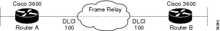
Two Routers Using Frame Relay Fragmentation Example
Figure 75 shows an example of Frame Relay fragmentation between two routers. This configuration uses FRF.12 fragmentation.
Figure 75 Two Routers Using Frame Relay Fragmentation
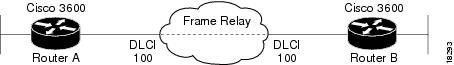
Two Routers Using a VoFR PVC Example
Figure 76 shows an example of two routers that use FRF.11 Annex C fragmentation with connections using a VoFR PVC.
Figure 76 Two Cisco 3600 Series Routers Using a VoFR PVC
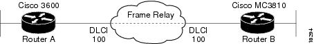
Router Using VoFR PVCs Connected to Cisco MC3810s Before 12.1(2)T Example
Figure 77 shows an example of a Cisco 3600 series router with connections to a Cisco MC3810 multiservice concentrator running a Cisco IOS release before12.1(2)T. In this example, the VoFR interface on both the Cisco 3600 series router and the Cisco MC3810 multiservice concentrator is configured by using the vofr cisco command. This configuration uses FRF.11 Annex C fragmentation.
Figure 77 Router Using VoFR PVCs Connected to a Cisco MC3810 Multiservice Concentrator
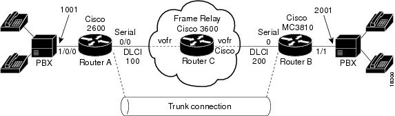
Cisco Trunk Calls Between Two Routers Example
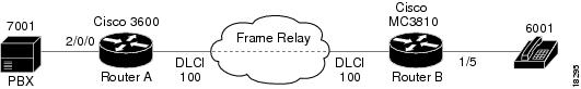
Figure 78 shows an example of VoFR Cisco trunk calls between two routers.
Figure 78 Cisco Trunk (Private-Line) Calls Between Two Routers
FRF.11 Trunk Calls Between Two Routers Example
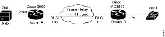
Figure 79 shows an example of FRF.11 trunk calls configured between two routers.
Figure 79 FRF.11 Trunk Calls Between Two Routers
Tandem Configuration Examples
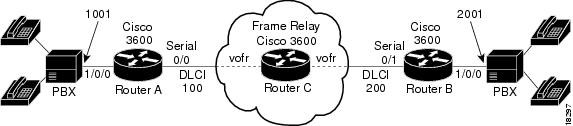
Figure 80 shows an example of a tandem configuration with two Cisco 3600 series routers as endpoints and a third Cisco 3600 series router as a tandem node.
Figure 80 Tandem Configuration with Three Routers for Switched Calls
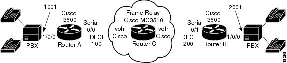
Figure 81 shows an example of a tandem configuration with a Cisco MC3810 multiservice concentrator acting as a tandem node.
Figure 81 Tandem Configuration with a Cisco MC3810 Multiservice Concentrator Tandem Node for Switched Calls
Figure 82 shows an example of a tandem configuration with a Cisco MC3810 multiservice concentrator acting as an endpoint node for Cisco trunk calls. When a Cisco MC3810 multiservice concentrator is on a VoFR network, the configuration for connections to and from the Cisco MC3810 multiservice concentrator is slightly different than for other routers that support VoFR. The vofr cisco command is required for those connections.
Figure 82 Tandem Configuration with a Cisco MC3810 Multiservice Concentrator Endpoint Node
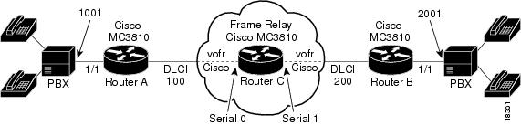
Figure 83 shows an example of a tandem configuration with Cisco MC3810 multiservice concentrators as both endpoint and tandem nodes.
Note
Figure 83 Configuration with All Cisco MC3810 Multiservice Concentrators as Endpoint and Tandem Nodes
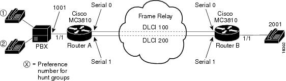
Cisco Trunk Call with Hunt Groups Example
Figure 84 shows an example of a Cisco trunk call with hunt groups configured. In this example, the two routers are in master-slave mode with a backup path. Router B is configured as a slave and Router A is configured as the master. The master makes periodic attempts to establish the trunk until the trunk is established.
Two dial peers match the destination string configured in the voice port, but one dial peer has a higher preference, so the call setup is attempted through that dial peer. If the call setup fails, the master can continue attempting call setups using the next available dial peer. After all dial peers are exhausted, the master can continue following the list cyclically by starting again from the dial peer with the highest preference.
Figure 84 Cisco Trunk Call with Hunt Groups