-
Cisco IOS Voice, Video, and Fax Configuration Guide, Release 12.2
-
About Cisco IOS Software Documentation
-
Using Cisco IOS Software
-
Voice, Video, and Fax Overview
-
Cisco Voice Telephony
-
Voice over IP Overview
-
Configuring Voice Ports
-
Configuring Dial Plans, Dial Peers, and Digit Manipulation
-
Configuring Quality of Service for Voice
-
H.323 Applications
-
Configuring H.323 Gateways
-
Configuring H.323 Gatekeepers
-
Configuring MGCP and Related Protocols
-
Configuring SIP for VoIP
-
Configuring Voice over Frame Relay
-
Configuring Voice over ATM
-
Configuring Tcl IVR Applications
-
Configuring Debit Card Applications
-
Configuring Settlement Applications
-
Configuring Trunk Connections and Conditioning Features
-
Configuring ISDN Interfaces for Voice
-
Configuring PBX Interconnectivity Features
-
Configuring Fax Applications
-
Configuring Modem Support for VoIP
-
Configuring Video Applications
-
Appendixes
-
Appendix A - Configuring Synchronized Clocking
-
Appendix B - Caller ID
-
Appendix C-Cisco Hoot and Holler over IP
-
Appendix D - Managing Cisco AS5300 Voice Feature Cards
-
Appendix E - Enhanced Voice Services for Japan for Cisco 800 Series Routers
-
Appendix F-Global System for Mobile Communications Full Rate and Enhanced Full Rate Codecs
-
Appendix G - Configuring the Cisco SS7/C7 Dial Access Solution System
-
-
 Feedback
Table Of Contents
Configuring Modem Transport Support for VoIP
Modem Transport Support Overview
Monitoring and Maintaining Modem Call Status
ISDN PRI-Requested Channel-Not-Available Traps
show controllers timeslots Command
Modem Transport Support Prerequisite Tasks
Modem Transport Support Configuration Task List
Enabling ISDN PRI-Requested Channel-Not-Available Traps
Configuring Modem Passthrough Globally
Configuring Modem Passthrough for a Specific Dial Peer
Troubleshooting Tips for Modem Passthrough
Monitoring and Maintaining Modem Passthrough
Modem Transport Support Configuration Examples
Modem Call Status Configuration Example
Modem Passthrough Configuration Example
Configuring Modem Transport Support for VoIP
This chapter explains how to configure modem transport support for Voice over IP (VoIP) and contains the following sections:
•
Modem Transport Support Overview
•
•
•
For a complete description of the commands used to configure VoIP for modem support, refer to the Cisco IOS Voice, Video, and Fax Command Reference. To locate documentation of other commands that appear in this chapter, use the command reference master index or search online.
To identify the hardware platform or software image information associated with a feature in this chapter, use the Feature Navigator on Cisco.com to search for information about the feature or refer to the software release notes for a specific release. For more information, see the "Identifying Supported Platforms" section in the "Using Cisco IOS Software" chapter.
Note
Modem Transport Support Overview
This section describes modem support features. Modem support includes two areas:
•
Monitoring and Maintaining Modem Call Status
Modem call status is supported by the following features and commands:
•
•
•
•
•
These features allow monitoring and maintaining of access server modem call status at digital signal level zero (DS-0), the PRI bearer channel level, and the modem level.
Modem call status offers the following benefits:
•
•
Note
DS-0 Busyout Traps
A DS-0 busyout trap is generated when any of the following conditions is met:
•
•
•
DS-0 busyout traps are generated at the DS-0 level for both channel-associated signalling (CAS) and ISDN configured lines.
ISDN PRI-Requested Channel-Not-Available Traps
ISDN PRI-requested channel-not-available traps are generated when a requested DS-0 channel is not available or when there is no modem available to take an incoming call. This feature is available only on ISDN PRI interfaces.
Modem Health Traps
Modem health traps are generated when a modem port is bad, disabled, reflashed, or shut down, or when there is a request to busy out the modem.
show controllers timeslots Command
The show controllers command, with the keyword timeslots, displays the channel state in detail. This command shows whether the DS-0 channels of a particular controller are in idle, in-service, maintenance, or busyout states. The show controllers command applies to both CAS and ISDN PRI interfaces.
DS-1 Loopback Traps
DS-1 loopback traps are generated when a DS-1 line goes into loopback mode.
Modem Passthrough over VoIP
Modem passthrough over VoIP provides for the transport of modem signals through a packet network by using pulse code modulation (PCM)-encoded packets.
Modem passthrough performs the following functions:
•
•
•
•
•
Modem passthrough offers the following benefits:
•
•
•
•
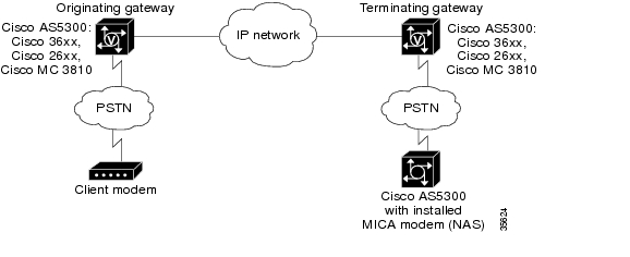
Figure 124 illustrates the connection from the client modem to a modem ISDN channel aggregation (MICA) technologies modem network access server (NAS).
Figure 124 Modem Passthrough Connection
Modem Tone Detection
The gateway detects modems operating at speeds up to V.90.
Passthrough Switchover
See Figure 124. When the gateway detects a data modem, both the originating gateway and the terminating gateway roll over to G.711. The rollover to G.711 disables the high-pass filter, disables echo cancellation, and disables VAD. At the end of the modem call, the voice ports revert to their prior configuration, and the digital signal processor (DSP) goes back to the state it was in before switchover.
For more information about modem passthrough, see the "Configuring Modem Passthrough" section later in this chapter.
Controlled Redundancy
You can enable payload redundancy so that the modem passthrough over VoIP switchover causes the gateway to emit redundant packets.
Packet Size
When redundancy is enabled, 10-ms sample-sized packets are sent. When redundancy is disabled, 20-ms sample-sized packets are sent.
Clock Slip Buffer Management
When the originating gateway detects a data modem, both the originating gateway and the terminating gateway switch from using dynamic jitter buffers to using static jitter buffers of 200-ms depth. The switch from dynamic to static compensates for Public Switched Telephone Network (PSTN) clocking differences at the originating gateway and the terminating gateway. At the modem call conclusion, the voice ports revert to using dynamic jitter buffers.
Modem Transport Support Prerequisite Tasks
Before configuring your access server to monitor modem call status, perform the following tasks:
•
•
snmp-server community public ROsnmp-server host 10.1.2.3 publicFor more information on these commands, refer to the Cisco IOS Configuration Fundamentals Command Reference.
Before configuring your access server for modem passthrough, perform the following tasks:
•
•
Modem Transport Support Configuration Task List
To configure modem support, perform the tasks described in the following sections:
•
•
Configuring Modem Call Status
To configure modem call status, perform the tasks in the following sections. All four sections are optional.
•
Enabling DS-0 Busyout Traps
DS-0 busyout traps are supported on the Cisco AS5300 and Cisco AS5800 universal access servers beginning with Cisco IOS Release 12.2. If you are using another Cisco IOS release, use the Feature Navigator on Cisco.com to determine which platforms support this feature.
To generate DS-0 busyout traps, use the following command in global configuration mode:
Enabling ISDN PRI-Requested Channel-Not-Available Traps
ISDN PRI-requested channel-not-available traps are supported on the Cisco AS5300 and Cisco AS5800 universal access servers beginning with Cisco IOS Release 12.2. If you are using another Cisco IOS release, use the Feature Navigator on Cisco.com to determine which platforms support this feature.
To generate ISDN PRI-requested channel-not-available traps, use the following command in global configuration mode:
Enabling Modem Health Traps
Modem health traps are supported on the Cisco AS5300 and Cisco AS5800 universal access servers beginning with Cisco IOS Release 12.2. If you are using another Cisco IOS release, use the Feature Navigator on Cisco.com to determine which platforms support this feature.
To generate modem health traps, use the following command in global configuration mode:
Enabling DS-1 Loopback Traps
DS-1 loopback traps are supported on the Cisco AS5300 universal access server beginning with Cisco IOS Release 12.2. If you are using another Cisco IOS release, use the Feature Navigator on Cisco.com to determine which platforms support this feature.
To generate DS-1 loopback traps, use the following command in global configuration mode:
Verifying Enabled Traps
Use the show running-config command to verify that the traps are enabled. The following output indicates that all the traps are enabled:
...Router(config)# show running-configsnmp-server enable traps ds0-busyoutsnmp-server enable traps isdn chan-not-availsnmp-server enable traps modem-healthsnmp-server enable traps ds1-loopback...Troubleshooting Tips
To troubleshoot the traps, enable debugging for SNMP packets by entering the debug snmp packets command in privileged EXEC mode. Check the resulting output to see that the SNMP trap information packet is being sent. The output will vary according to the kind of packet sent or received.
The following example shows the debug snmp packets command followed by an excerpt from the debug output. The first and last lines of the sample output show SNMP trap packets that have been sent and received.
Router# debug snmp packetsSNMP: Packet received via UDP from 10.5.4.1 on Ethernet0SNMP: Get-next request, reqid 23584, errstat 0, erridx 0sysUpTime = NULL TYPE/VALUEsystem.1 = NULL TYPE/VALUEsystem.6 = NULL TYPE/VALUESNMP: Response, reqid 23584, errstat 0, erridx 0sysUpTime.0 = 2217027system.1.0 = Cisco Internetwork Operating System Softwaresystem.6.0 =SNMP: Packet sent via UDP to 10.5.4.1You can also use trap monitoring and logging tools such as snmptrapd with debugging flags turned on to monitor output.
Configuring Modem Passthrough
Modem passthrough over VoIP capability is supported on the Cisco AS5300 universal access server beginning with Cisco IOS Release 12.2. If you are using another Cisco IOS release, use the Feature Navigator on Cisco.com to determine which platforms support this feature.
By default, modem passthrough over VoIP capability and redundancy are disabled.
Tips
Redundancy can be enabled in one or both of the gateways. When only a single gateway is configured for redundancy, the other gateway receives the packets correctly but does not produce redundant packets.
Modem passthrough can be configured either globally or for a specific dial peer, or both. If modem passthrough is configured both globally and for a specific dial peer, the dial peer configuration takes precedence over the global configuration. Consequently, when a call matches a particular dial peer, the access server first applies the modem passthrough configuration on the dial peer. Then, if a specific dial peer is not configured, the access server will use the global configuration. The following sections explain further:
•
•
Configuring Modem Passthrough Globally
For the Modem Passthrough over VoIP feature to operate, you need to configure modem passthrough in both the originating gateway and the terminating gateway so that the modem call matches a voip dial-peer on the gateway.
When using the voice service voip and modem passthrough nse commands on a terminating gateway to globally set up fax or modem pass-through with NSEs, you must also ensure that each incoming call will be associated with a VoIP dial peer to retrieve the global fax or modem configuration. You associate calls with dial peers by using the incoming called-number command to specify a sequence of digits that incoming calls can match. You can ensure that all calls will match at least one dial peer by using the following commands:
Router(config)# dial-peer voice tag voipRouter(config-dial-peer)# incoming called-number .To configure modem passthrough for all the dial peers of a gateway, use the following commands beginning in global configuration mode:
Configuring Modem Passthrough for a Specific Dial Peer
Modem passthrough is disabled by default for all dial peers on the gateway. You can configure modem passthrough on a specific dial peer by entering dial-peer configuration mode for the specific dial peer.
You must configure a VoIP dial peer on both the originating and terminating gateways to match the call—for example, using a destination pattern. The modem passthrough parameters associated with those dial peers will then apply to the calls between them.
Note
To configure modem passthrough for a specific dial peer, use the following commands beginning in global configuration mode:
Verifying Modem Passthrough
To verify that modem passthrough is enabled, use the following commands:
•
•
Troubleshooting Tips for Modem Passthrough
To troubleshoot modem passthrough, perform the following checks:
•
•
•
•
•
Monitoring and Maintaining Modem Passthrough
To monitor and maintain modem passthrough, use the following commands in privileged EXEC mode, as needed:
Modem Transport Support Configuration Examples
This section provides the following specific configuration examples for modem support:
•
•
Modem Call Status Configuration Example
The following example shows sample configuration output with DS-0 busyout traps enabled:
version 12.2service timestamps debug uptimeservice timestamps log uptimeno service password-encryption!hostname router!aaa new-modelaaa authentication ppp default group radiusenable password <password>!spe 1/0 1/7firmware location system:/ucode/mica_port_firmwarespe 2/0 2/7firmware location system:/ucode/mica_port_firmware!resource-pool disable!clock timezone PDT -8clock calendar-validno modem fast-answermodem country mica usamodem link-info poll time 60modem buffer-size 300ip subnet-zero!isdn switch-type primary-5essisdn voice-call-failure 0!controller T1 0framing esfclock source line primarylinecode b8zspri-group timeslots 1-24!controller T1 1framing esflinecode b8zsds0-group 0 timeslots 1-24 type e&m-fgbcas-custom 0!interface Loopback0ip address 10.5.4.1!interface Ethernet0no ip addressshutdown!interface Serial0no ip addressshutdown!interface Serial1no ip addressshutdown!interface Serial0:23no ip addressip mroute-cacheisdn switch-type primary-5essisdn incoming-voice modemno cdp enable!interface FastEthernet0ip address 10.5.4.1duplex fullspeed autono cdp enable!interface Group-Async1ip unnumbered FastEthernet0encapsulation pppip tcp header-compression passiveno ip mroute-cacheasync mode interactivepeer default ip address pool swattestno fair-queueppp authentication chapppp multilinkgroup-range 1 192!interface Dialer1ip unnumbered FastEthernet0encapsulation pppip tcp header-compression passivedialer-group 1peer default ip address pool swattestpulse-time 0no cdp enable!ip local pool swattest 10.5.4.1ip default-gateway 10.5.4.1ip classless!dialer-list 1 protocol ip permitsnmp-server engineID local 00000009020000D058890CF0snmp-server community public ROsnmp-server packetsize 2048snmp-server enable traps popsnmp-server host 10.5.4.1 public!radius-server host 10.5.4.1 auth-port 1645 acct-port 1646radius-server retransmit 3radius-server key <password>!line con 0transport input noneline 1 192autoselect pppmodem InOuttransport preferred nonetransport input alltransport output noneline aux 0line vty 0 4endModem Passthrough Configuration Example
The following example shows a sample configuration for modem passthrough:
version 12.2service timestamps debug uptimeservice timestamps log uptimeno service password-encryption!voice service voipmodem passthrough nse codec g711ulaw redundancy maximum-session 5!resource-pool disable!ip subnet-zeroip ftp source-interface Ethernet0ip ftp username labip ftp password labno ip domain-lookup!isdn switch-type primary-5esscns event-service server!mta receive maximum-recipients 0!controller T1 0framing esfclock source line primarylinecode b8zspri-group timeslots 1-24!controller T1 1shutdownclock source line secondary 1!interface Ethernet0ip address 1.1.2.2 255.0.0.0no ip route-cacheno ip mroute-cache!interface Serial0:23no ip addressencapsulation pppip mroute-cacheno logging event link-statusisdn switch-type primary-5essisdn incoming-voice modemno peer default ip addressno fair-queueno cdp enableno ppp lcp fast-start!interface FastEthernet0ip address 26.0.0.1 255.0.0.0no ip route-cacheno ip mroute-cacheload-interval 30duplex fullspeed autono cdp enable!ip classlessip route 17.18.0.0 255.255.0.0 1.1.1.1no ip http server!voice-port 0:D!dial-peer voice 1 potsincoming called-number 55511..destination-pattern 020..direct-inward-dialport 0:Dprefix 020!dial-peer voice 2 voipincoming called-number 020..destination-pattern 55511..modem passthrough nse codec g711ulaw redundancysession target ipv4:26.0.0.2!line con 0exec-timeout 0 0transport input noneline aux 0line vty 0 4login!end