-
Cisco IOS Voice, Video, and Fax Configuration Guide, Release 12.2
-
About Cisco IOS Software Documentation
-
Using Cisco IOS Software
-
Voice, Video, and Fax Overview
-
Cisco Voice Telephony
-
Voice over IP Overview
-
Configuring Voice Ports
-
Configuring Dial Plans, Dial Peers, and Digit Manipulation
-
Configuring Quality of Service for Voice
-
H.323 Applications
-
Configuring H.323 Gateways
-
Configuring H.323 Gatekeepers
-
Configuring MGCP and Related Protocols
-
Configuring SIP for VoIP
-
Configuring Voice over Frame Relay
-
Configuring Voice over ATM
-
Configuring Tcl IVR Applications
-
Configuring Debit Card Applications
-
Configuring Settlement Applications
-
Configuring Trunk Connections and Conditioning Features
-
Configuring ISDN Interfaces for Voice
-
Configuring PBX Interconnectivity Features
-
Configuring Fax Applications
-
Configuring Modem Support for VoIP
-
Configuring Video Applications
-
Appendixes
-
Appendix A - Configuring Synchronized Clocking
-
Appendix B - Caller ID
-
Appendix C-Cisco Hoot and Holler over IP
-
Appendix D - Managing Cisco AS5300 Voice Feature Cards
-
Appendix E - Enhanced Voice Services for Japan for Cisco 800 Series Routers
-
Appendix F-Global System for Mobile Communications Full Rate and Enhanced Full Rate Codecs
-
Appendix G - Configuring the Cisco SS7/C7 Dial Access Solution System
-
-
 Feedback
Table Of Contents
Configuring Trunk Connections and Conditioning Features
Trunk Conditioning Signaling Attributes
Congestion Monitoring and Management Features
Calculated Impairment Planning Factor
Trunk Management Prerequisite Tasks
Configuring Trunk-Conditioning Signaling Attributes
Assigning Trunk-Conditioning Attributes to Network Dial Peers
Assigning Voice Classes to Voice Ports
Verifying the Signaling Attributes and Trunk Conditioning
Configuring PLAR (Switched) Connections
Configuring Trunk/Tie-Line Connections
Configuring PLAR-OPX Connections
Configuring T1/E1 Alarm Generation Parameters
Verifying Alarm-Generation Parameters
Configuring Fallback to Alternate Dial Peers
Configuring Destination Monitoring without Fallback to Alternate Dial Peers
Configuring Call Fallback Cache Parameters
Configuring Call Fallback Jitter-Probe Parameters
Configuring Call Fallback Probe-Timeout and Weight Parameters
Configuring Call Fallback Threshold Parameters
Configuring Call Fallback Map Parameters
Verifying PSTN Fallback Configuration
Monitoring and Maintaining PSTN Fallback
Configuring Local Voice Busyout
Configuring the Busyout Trigger Event
Configuring Busyout of Voice Ports
Configuring a Voice Port to Monitor the Link to a Remote Interface
Configuring a Busyout Monitoring Voice Class
Trunk Connections and Conditioning Configuration Examples
Trunk Conditioning Configuration Example
Voice Class for VoFR and VoATM Dial Peers Configuration Example
Voice Class for Voice Ports Configuration Example
Voice Class for Default Signaling Patterns Configuration Example
Voice Class for Specified Signaling Patterns Configuration Example
PLAR (Switched Calls) Configuration Example
Permanent Trunks Configuration Example
Congestion Monitoring and Management Configuration Examples
Configuring PSTN Fallback for VoIP over Frame Relay Example
Configuring PSTN Fallback for VoIP over MLP Example
Local Voice Busyout Configuration Examples
Alarm Trigger for Busyout of Voice Ports Configuration Example
Configuring Trunk Connections and Conditioning Features
This chapter describes trunk connections and conditioning features for the Cisco 2600 and 3600 series routers and MC3810 multiservice concentrators. The features include trunk conditioning, tie-line simulation, T1/E1 alarms, Public Switched Telephone Network (PSTN) fallback, and busyout. This chapter contains:
•
Trunk Conditioning Signaling Attributes
•
•
•
•
•
•
For a complete description of the commands in this chapter, refer to the Cisco IOS Voice, Video, and Fax Command Reference. To locate documentation of other commands that appear in this chapter, use the command reference master index or search online.
To identify the hardware platform or software image information associated with a feature in this chapter, use the Feature Navigator on Cisco.com to search for information about the feature or refer to the software release notes for a specific release. For more information, see the "Identifying Supported Platforms" section in the "Using Cisco IOS Software" chapter.
Trunking Overview
A trunk is a communication line between two switching systems—the switching equipment in a central office (CO) and PBX. It is a physical and logical point-to-point connection with a permanent wire over which network traffic travels. A backbone is composed of a number of trunks.
Voice over IP (VoIP) simulates trunk connections. The simulated connections occur between PBXs that are connected to Cisco routers or access servers on each side of the network
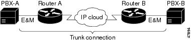
In Figure 103, two PBXs are connected to a router using a simulated trunk and a recEive and transMit (E&M) voice port. In this case, a permanent, non-switched connection transparently connects the two PBXs.
Figure 103 Simulated Trunk Connection
Simulated Lines and Trunks
Simulated lines and trunks enable a telephone user at one location to dial an access code to access a PBX at another location. A second dial tone can be heard coming from the remote PBX. There are two types of simulated connections—switched and permanent—that can be configured for both analog and digital systems. The connections are created with the Cisco connection command.
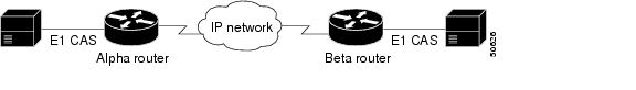
The connection trunk command creates a permanent call that is connected as soon as the routers on each end are booted (see Figure 104). Permanent calls pass limited telephony signaling and operate without collecting digits or requiring changes to the overall dial plan.
Figure 104 Connection Trunk Configuration
The calls simulate a permanent tie-line between two PBXs. Both ends must be configured and have compatible voice-port signaling that is:
•
•
The signaling cannot be FXO to ground start.
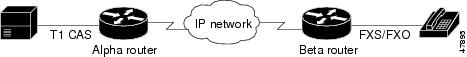
When a switched call is configured (see Figure 105), the user can make a call without dialing any digits. The telephony signaling, such as hookflash, is not passed. The call will not roll over to voice mail if the remote telephone does not answer and digits from an attached telephony device are not collected.
Figure 105 Connection Private-Line Auto Ringback (PLAR) Configuration
The switched call configuration works with any type of voice port (E&M, FXO, or FXS) and can be used without any effect on an existing dial plan. It is commonly used to connect PBXs in which the remote devices appear to be physical extensions. The PBX provides dial tone to the extensions, not the router.
The connection tie-line command creates a switched call between two stations or PBXs that bypasses the switch. The connection plar-opx command creates a call that is similar to a switched call. The connection does not take place between the PBX and the local router until the far-end FXS device answers. This enables the PBX to provide centralized voice mail or attendant services when the remote device does not answer.
Trunk Conditioning Signaling Attributes
Trunk conditioning signaling attributes apply to permanent point-to-point voice connections (private lines and tie-lines) created using the connection trunk command. This feature provides the following capabilities:
•
•
•
Trunk conditioning enables greater control over Cisco private-line calls that are sent over Frame Relay or ATM networks. When private-line or tie-line calls are sent between two PBXs, fault indications are sent to the sending PBX. If the call fails, the PBX is able to select an alternate path to route the calls. Selecting an alternate path applies to analog connections or digital T1/E1 using channel-associated signaling (CAS)/robbed-bit ABCD signaling. It does not cover common channel signaling (CCS).
When T1/E1 CAS is carried in transparent pass-through mode for arbitrary, unknown, or unsupported CAS protocols, it is necessary to define on-hook/idle patterns so that the domain specific part (DSP)/signaling code can sense the idle call state and shut off the flow of voice packets when no active call is in progress. This mode provides an additional idle bandwidth-saving mechanism for those cases when Voice Activity Detection (VAD) is not desired.
Note
Congestion Monitoring and Management Features
Congestion monitoring of permanent and switched calls is performed with these features: T1/E1 alarm conditioning, PSTN fallback, and busyout functionality including busyout monitoring. These features provides the following capabilities:
•
•
An OOS condition can be signalled using an ABCD bit pattern that is different from the busy or seized state. The difference enables the PBX to differentiate between OOS and congestion.
T1/E1 Alarm Conditioning
Alarm conditioning provides status monitoring on T1/E1 PBX voice interfaces for simulated lines and trunks created using the connection command. It supports operation with CAS, but does not support CCS.
A T1/E1 alarm can be triggered by events detected through the monitoring of a specified set of voice ports within a T1/E1 trunk. A monitored set includes a defined voice port that has a specified DS0 group or groups and configured for one of the following:
•
•
When all the monitored voice ports on a T1/E1 trunk are OOS (PVCs are OOS and SVCs are busied out), a T1/E1 Alarm Indication Signal (AIS) is generated on the T1/E1 trunk connected to the PBX or PSTN.
Note
PSTN Fallback
PSTN fallback monitors congestion in the IP network and redirects calls to the PSTN or reject calls based on the network congestion. PSTN fallback is supported on Cisco 2600 and 3600 series routers and Cisco MC3810 multiservice concentrators. For information concerning Voice over IP (VoIP), Voice over ATM (ATM), Calculated Impairment Planning Factor (ICPIF), and Service Assurance Agent (SAA), see the following:
•
•
•
•
•
•
PSTN fallback can re-routed calls to an alternate IP destination or to the PSTN if the IP network is found unsuitable for voice traffic at that time. The user defines the congestion thresholds based on the configured network. This functionality enables the service provider to give a reasonable guarantee about the quality of the conversation to their VoIP users at the time of call admission.
Note
PSTN fallback includes the following features:
•
–
–
•
•
The fallback subsystem has a network traffic cache that maintains the ICPIF or delay/loss values for various destinations. The subsystem helps performance, because new calls to a well-known destination do not have to wait on a probe. The value is usually cached from a previous call.
Once the ICPIF or delay/loss values are calculated and stored, the values remain until the cache ages out or overflows. Until an entry ages out, probes are sent periodically for that destination. The time interval is user configurable. In the following example, it is assumed that call fallback active is enabled and an ICPIF threshold is defined. The call control would be similar if loss and delay thresholds were defined.
Step 1
Note
Step 2
Note
Step 3
If the timeout threshold is set and the router has not received calls for a particular destination after the threshold expires, then the router removes that destination's traffic information from the cache.
Calculated Impairment Planning Factor
ICPIF calculates an impairment factor for every piece of equipment along the voice path and adds the values to get the total impairment. The ITU assigns the different types of impairments, such as noise, delay, and echo.
The ICPIF handling has been introduced for compatibility with Cisco H.323. Part of ICPIF includes a concept of Total Impairment Value that is a function of loss of packets, delay of packets, and codecs used based on the round-trip reports from SAA. For this feature, all codecs are classified as 729 class codecs or 711 class codecs.
Service Assurance Agent
SAA is a network congestion analysis mechanism. SAA provides delay, jitter, and packet loss information for the configured IP addresses. SAA is based on a client-server protocol defined on UDP. It has an Message Digest 5 (MD5), which is a message authentication algorithm in SNMP v.2. MD5 verifies the integrity of the communication, authenticates the origin, and checks for timeliness.
SAA uses UDP port (port 1976) for sending the SAA control message to the terminating gateway. The SAA probe packets go out on randomly selected ports from the top end of the audio UDP port range (16384 - 32767).
The port pair (RTP & Real-Time Transport Control Protocol [RTCP] port) is selected, and by default SAA for call fallback uses the RTCP port (odd number) to avoid going into the priority queue, if enabled. If fallback is configured to use the priority queue, the RTP port (even number) is selected. The audio UDP port range must be included in the priority queue for fallback priority queueing to work.
Busyout
Three busyout conditions are discussed in the following sections:
Local Voice Busyout
Local voice busyout is designed to busy out trunks assigned to PVCs so that the PBX does not seize the circuit. Local voice busyout enables the PBX to route a call based on the actual availability of trunks. Local voice busyout enables the following:
•
•
When ports are marked busy, a call is forced back to the originating equipment (typically a PBX) that reroutes the call over an alternate path. This action ensures that a caller does not experience "dead air" resulting from a connection that never terminates.
The local voice busyout feature provides a way to busy out a voice port if a monitored network interface changes state. When a monitored interface changes to a specified state—to OOS or in-service—the voice port presents a seized/busyout condition to the attached PBX or other customer premises equipment (CPE). The PBX or other CPE can then attempt to select an alternate route.
Local voice busyout is different from busy-back. Busy-back refers to the signal sent from within the network to the calling party that indicates a busy (or congested) state anywhere along the route, up to and including the condition of the called party.
Note
Advanced Voice Busyout
Advanced voice busyout monitors links to remote and IP-addressable interfaces and uses an SAA probe signal for VoIP. Voice classes are configured to simplify and speed up the configuration of voice busyout on multiple voice ports. SAA probe monitoring of remote interfaces is intended for use with VoIP, VoFR, and VoATM networks.
Busyout Monitor
Busyout monitor is one aspect of Call Admission Control (CAC) that uses a data network and the PSTN to provide the best possible quality and cost savings for VoIP calls. Busyout monitor CAC functionality also provides the following:
•
•
•
Trunk Management Prerequisite Tasks
Before configuring the trunk connections and conditioning features, the one of the following must be configured:
•
•
•
•
Before configuring the congestion-monitoring features, the following requirements must be met:
•
–
–
–
•
•
–
–
–
–
–
Note
This section includes procedures for configuring the following trunk management features:
•
•
•
•
–
–
–
•
•
Configuring Trunk-Conditioning Signaling Attributes
Different trunk-conditioning signaling attributes may be required to match the characteristics of the different PBXs to which the router connects. For this reason, trunk-conditioning attributes are configured by creating a voice class for each set of attributes required. The trunk-conditioning attributes are configured for the voice class and the voice class is assigned to one or more dial peers.
A voice class must be configured and assigned to at least one dial peer before the trunk conditioning signaling attributes take effect.
Note
To create a voice class and define the trunk-conditioning attributes, use the following commands beginning in global configuration mode:
Assigning Trunk-Conditioning Attributes to Network Dial Peers
After the voice class has been created, it must be applied to the dial-peer configuration. The trunk-conditioning attributes can be assigned to VoIP, VoFR, or VoATM dial peers, but not to POTS dial peers.
Note
To apply trunk-conditioning signaling attributes to a network dial peer, specify the dial peer type and then use the following command in dial-peer voice configuration mode:
Assigning Voice Classes to Voice Ports
To assign a voice class to a voice port, specify the voice port, and then use the following command in voice-port configuration mode:
Verifying the Signaling Attributes and Trunk Conditioning
To verify the signaling attributes (timing parameters) using voice-port 1/5 on a Cisco MC3810 multiservice concentrator, enter the show voice trunk-conditioning signaling command. The following is a sample output from this command:
Router# show voice trunk-conditioning signaling 1/51/5 :TX INFO :slow-mode seq#= 25, sig pkt cnt= 42, last-ABCD=0000hardware-state ACTIVE signal type is NorthamericanCASsignal path is OPEN0000 0000 0000 0000 0000 0000 0000 0000 0000 00000000 0000 0000 0000 0000 0000 0000 0000 0000 00000000 0000 0000 0000 0000 0000 0000 0000 0000 0000RX INFO :slow-mode, sig pkt cnt= 37missing = 0, out of seq = 0, very late = 0playout depth = 0 (ms), refill count = 1prev-seq#= 25, last-ABCD=0000trunk_down_timer = 4212 (ms), idle timer = 0 (sec),tx_oos_timer = 0 (sec), rx_ais_duration = 0 (ms)forced playout signal pattern = NONEsignaling playout history0000 0000 0000 0000 0000 0000 0000 0000 0000 00000000 0000 0000 0000 0000 0000 0000 0000 0000 00000000 0000 0000 0000 0000 0000 0000 0000 0000 0000To verify the status of trunk supervision and configuration parameters on a Cisco MC3810 multiservice concentrator, enter the show voice trunk-conditioning supervisory command. The following is a sample output from this command.
Router# show voice trunk-conditioning supervisory 1/51/5 : state : TRUNK_SC_CONNECT, voice : on, signal : on, slavestatus: trunk connectedsequence oos : idle and oospattern :rx_idle = 0x0 rx_oos = 0xF tx_oos = 0xFtiming : idle = 0, restart = 0, standby = 0, timeout = 40supp_all = 50, supp_voice = 0, keep_alive = 5timer: oos_ais_timer = 0, timer = 0To verify signaling and timing parameters for the configuration for voice-ports 0:0, 0:1, and 0:2 on a Cisco MC3810 multiservice concentrator, enter the show running-config command. The trunks do not have to be connected and active. The following is a sample output from this command.
Router# show running-configBuilding configuration...Current configuration:...voice class permanent 100signal timing idle suppress-voice 2000signal timing oos restart 1000...voice-port 0:0voice-class permanent 100compand-type a-law!voice-port 0:1voice-class permanent 100compand-type a-law!voice-port 0:2voice-class permanent 100compand-type a-law...To display the status of trunk-conditioning signaling and timing parameters for a voice port on a Cisco MC3810 multiservice concentrator, enter one of the following commands:
•
Router# show voice trunk-conditioning signaling 1/51/5 :TX INFO :slow-mode seq#= 25, sig pkt cnt= 42, last-ABCD=0000hardware-state ACTIVE signal type is NorthamericanCASsignal path is OPEN0000 0000 0000 0000 0000 0000 0000 0000 0000 00000000 0000 0000 0000 0000 0000 0000 0000 0000 00000000 0000 0000 0000 0000 0000 0000 0000 0000 0000RX INFO :slow-mode, sig pkt cnt= 37missing = 0, out of seq = 0, very late = 0playout depth = 0 (ms), refill count = 1prev-seq#= 25, last-ABCD=0000trunk_down_timer = 4212 (ms), idle timer = 0 (sec),tx_oos_timer = 0 (sec), rx_ais_duration = 0 (ms)forced playout signal pattern = NONEsignaling playout history0000 0000 0000 0000 0000 0000 0000 0000 0000 00000000 0000 0000 0000 0000 0000 0000 0000 0000 00000000 0000 0000 0000 0000 0000 0000 0000 0000 0000•
Router# show voice trunk-conditioning signaling summary1/1 is shutdown1/4 is shutdown1/5 :TX INFO :slow-mode seq#= 25, sig pkt cnt= 40, last-ABCD=0000hardware-state ACTIVE signal type is NorthamericanCAS signal path is OPENRX INFO :slow-mode, sig pkt cnt= 36, prev-seq#= 25, last-ABCD=0000•
Router# show voice call summaryPORT CODEC VAD VTSP STATE VPM STATE========= ======== === ===================== ========================1/1 *shutdown*1/2 - - - FXSLS_ONHOOK1/3 - - - FXSLS_ONHOOK1/4 *shutdown*1/5 g729r8 n S_CONNECT S_TRUNKED1/6 - - - EM_ONHOOKConfiguring Trunk Connections
This section covers the following three types of trunk connections:
•
•
•
Configuring PLAR (Switched) Connections
To configure a PLAR connection, enter voice-port configuration mode for the required voice port.
Note
To configure a PLAR connection, use the following command in voice-port configuration mode:
Configuring Trunk/Tie-Line Connections
The following restrictions apply to the trunk/tie-line configuration:
•
•
–
–
–
•
•
•
To configure a trunk or tie-line connection, use the following commands in dial-peer configuration mode for the required POTS dial peer:
Configuring PLAR-OPX Connections
The plar-opx command is specific to the Cisco MC3810 concentrator and configures an OPX connection. The local voice port provides a local response before the remote voice port receives an answer. On FXO interfaces, the voice port does not answer until the remote side answers.
To configure a PLAR-OPX connection, use the following command in voice-port configuration mode for the required voice port:
Router(config-voice-port)# connection plar-opx string
Specifies a PLAR-OPX connection, associating a peer directly with an interface.
Configuring T1/E1 Alarm Generation Parameters
A network can be configured to monitor any combination of DS0 groups on a T1 or E1 trunk. An alarm is triggered only if all of the monitored DS0 groups on a T1 or E1 trunk are OOS. If one monitored DS0 group is in service, no alarm is triggered. The DS0 groups can be either of the following types:
•
•
Note
To specify the DS0 group to be monitored and the alarm type, use the following commands beginning in global configuration mode:
Verifying Alarm-Generation Parameters
Use one or more of the following methods to verify that the T1/E1 controller is correctly configured for generating alarms:
•
Router# show running-configBuilding configuration....controller E1 0mode casds0-group 0 timeslots 1-10 type e&m-immediate-startds0-group 1 timeslots 11-15,17-20 type e&m-immediate-startds0-group 2 timeslots 21-30 type e&m-immediate-startalarm-trigger blue 0-2•
–
Step 1. Shut down or disconnect any serial and Ethernet interfaces that are monitored for OOS busyout.Step 2. Activate any serial and Ethernet interfaces that are monitored for in-service busyout.
Note
–
•
Router# show controller t1 0T1 0 is up.Applique type is Channelized T1Cablelength is long gain36 0dbYellow alarm detected.alarm-trigger is set to BlueAlarm is triggeredSlot 3 CSU Serial #00000056 Model TEB HWVersion 3.70 RX level = 0DBFraming is ESF, Line Code is B8ZS, Clock Source is Line.Data in current interval (827 seconds elapsed):Configuring PSTN Fallback
The following restrictions and limitations apply to PSTN fallback:
•
•
•
•
The following sections describe the configuration tasks for PSTN fallback. Each task in the list is identified as either optional or required:
•
•
•
•
•
•
•
Configuring Fallback to Alternate Dial Peers
To configure fallback to alternate dial peers in case of network congestion, use the following command in global configuration mode:
Configuring Destination Monitoring without Fallback to Alternate Dial Peers
To monitor call destinations without fallback to alternate dial peers, use the following command in global configuration mode:
Router(config)# call fallback monitor
Enables the monitoring of destinations without fallback to alternate dial peers.
Configuring Call Fallback Cache Parameters
To configure the call fallback cache parameters, use the following commands beginning in beginning in configuration mode:
Configuring Call Fallback Jitter-Probe Parameters
To configure the call fallback jitter-probe parameters, use the following commands in global configuration mode:
Configuring Call Fallback Probe-Timeout and Weight Parameters
To configure call fallback probe-timeout and weight parameters, use the following commands in global configuration mode:
Configuring Call Fallback Threshold Parameters
To configure the call fallback threshold parameters that monitor network traffic for call requests, use one of the following commands in global configuration mode:
Configuring Call Fallback Map Parameters
To configure the call fallback map parameters, use one of the following commands in global configuration mode:
Verifying PSTN Fallback Configuration
To verify the PSTN fallback configuration, use the following commands in EXEC mode, as needed:
Troubleshooting Tips
To troubleshoot PSTN fallback, use the following debug commands and ensure that VoIP is working before PSTN fallback is configured:
•
•
Monitoring and Maintaining PSTN Fallback
To monitor and maintain PSTN fallback, use the following commands in EXEC mode, as needed:
Configuring Local Voice Busyout
This section contains configuration information for the following features:
•
•
•
•
The following restrictions and limitations apply to the local voice busyout feature:
•
•
•
•
A busyout trigger event can be configured at both the serial interface level and the voice-port level. If there is a conflict between the interface-level trigger event and the voice-port level trigger event (trigger events for each are different), the voice-port-level trigger event overrides the interface level trigger event.
If more than one interface is configured for a busyout trigger event, voice ports are not busied out until all of the interfaces are down.
Note
Configuring the Busyout Trigger Event
To configure the voice-port busyout trigger event for a serial or ATM network interface, select the required interface and use the following commands beginning in interface configuration mode:
Step 1
Router(config-if)# voice-port busyout
Busies out all voice ports associated with this serial interface.
Note
Step 2
Router(config-if)# ctrl z
Exits interface configuration mode and enters EXEC mode.
Step 3
Router# show voice busyout
Displays the voice busyout status.
Note
Configuring Busyout of Voice Ports
A voice port can be configured to busy out under specified conditions or it can be manually forced into a busyout state using the following procedures:
•
•
The default is to busyout when the monitored interface is OOS.
Configuring Busyout Under Specified Conditions
To configure the busyout of a voice port under specified conditions, use the following command in voice-port configuration mode for the required voice port:
Configuring Seize Conditions
To configure seize conditions, use the following commands in voice-port configuration mode for the required voice port:
Note
The busyout seize action depends on the voice port signaling type. Table 45 contains information on the busyout actions that take place. For E&M voice ports, the busyout action is always seize.
Forcing the Voice Port into Busyout State
When busyout is configured, the specified voice port is forced into a busyout state when the interface is down. When the busyout forced command is entered, the voice port is forced unconditionally into a busyout state. If more than one interface has the voice-port busyout interface command configured, all interfaces must be down for the busyout to take effect.
To configure the voice port for a forced busyout state, use the following commands in voice-port configuration mode for the required voice port:
Note
Configuring a Voice Port to Monitor the Link to a Remote Interface
The following restrictions and limitations apply to SAA probe monitoring of remote interfaces:
•
•
•
•
•
•
•
•
Individual voice ports can be configured for busyout, or a voice class can be applied that includes all of the busyout parameters (see the "Assigning Voice Classes to Voice Ports" section).
Note
To configure a voice port to monitor the link to a remote interface, use the following command in voice-port configuration mode:
Verifying the Voice-Port Busyout Configuration
Complete the following tasks to verify that a voice port is correctly configured to monitor the link to a remote interface:
•
•
Router# show voice busyoutVoice port busyout will be triggered by thefollowing network interfaces states 1/1 probe 209.165.202.128 codec g711u icpif 25 1/2 probe 209.165.202.128 codec g711u icpif 25 1/3 probe 209.165.202.128 codec g711u icpif 25The following voice ports are in busyout state1/1 is in busyout state caused by probe 209.165.202.128 codec g711u icpif 21/2 is in busyout state caused by probe 209.165.202.128 codec g711u icpif 21/3 is in busyout state caused by probe 209.165.202.128 codec g711u icpif 2Configuring a Busyout Monitoring Voice Class
A busyout voice class monitors local ports (serial and Ethernet) and links to remote IP addresses. Busyout occurs when all of the monitored local ports are OOS or when all of the monitored links go below the configured threshold value. If a voice port is configured to monitor multiple links, busyout occurs only when all of the monitored links go below the threshold.
To define a voice class with specified busyout conditions, use the following commands beginning in global configuration mode:
Step 1
Router(config)# voice class busyout tag
Creates a voice class for defining busyout conditions. The range for the tag number is 1 to 10000. The tag number must be unique on the router.
Step 2
Router(config-voice-class)# busyout monitor serial interface-number [in-service]
(Optional) Specifies a local serial interface to be monitored by the voice port. To configure the voice port to monitor multiple interfaces, reenter the command for each additional interface to be monitored.1
Step 3
Router(config-voice-class)# busyout monitor ethernet interface-number} [in-service]
(Optional) Specifies a local Ethernet interface to be monitored by the voice port. To configure the voice port to monitor multiple interfaces, reenter the command for each additional interface.1
Step 4
Router(config-voice-class)# busyout monitor probe ip-address [codec codec-type] [icpif number | loss loss-value delay milliseconds]
(Optional) Configures the voice port to use an SAA probe to monitor the link to the remote interface identified by an IP address.
(Optional) Specifies a codec profile for the SAA probe signal and ICPIF loss/delay threshold or loss and delay thresholds individually. Packet loss and delay determine the threshold for initiating the busyout state.
Note
If a threshold value is not entered, the packet delay values from the call fallback active command are used.
Note
1 The default is that the voice port is busied out when the monitored interface is OOS. Enter the keyword in-service to configure the voice port for busyout when the monitored interface comes into service. If a voice port is configured to monitor multiple interfaces for OOS, busyout occurs only when all the monitored serial and Ethernet interfaces are OOS. If a voice port is configured to monitor multiple interfaces for the in-service state, busyout occurs when any one monitored serial or Ethernet interface comes into service.
After the voice class for the busyout function has been created, assign it to all voice ports that have these busyout requirements. See the "Assigning Voice Classes to Voice Ports" section.
Verifying the Voice- and Voice-Class Busyout Configuration
To verify the voice-class busyout, assign the voice class to a voice port as described in the "Assigning Voice Classes to Voice Ports" section, and verify the busyout function of the voice port.
To verify that a voice port is correctly configured for busyout monitoring, perform the following tasks:
•
–
–
The voice port monitors a remote IP address for OOS only.
Note
•
Router# show voice busyoutVoice port busyout will be triggered by the following network interfaces states 1/2 busyout monitor ATM0 1/3 busyout monitor ATM0 1/4 busyout monitor Serial0 1/5 busyout monitor Serial0 1/6 probe 209.165.202.128 codec g711u icpif 25The following voice ports are in busyout state1/1 is forced into busyout state 1/2 is in busyout state caused by ATM0 1/3 is in busyout state caused by ATM0 1/4 is in busyout state caused by Serial0 1/5 is in busyout state caused by Serial01/6 is in busyout state caused by probe 209.165.202.128 codec g711u icpif 2Trunk Connections and Conditioning Configuration Examples
This section has the following examples:
•
•
•
•
•
•
•
Trunk Conditioning Configuration Example
The following example configures a voice class and then applies it to a VoFR and VoATM dial peer on Cisco MC3810 series concentrators:
Router(config)# voice class permanent 10
Router(config-class)# signal keepalive 10
Router(config-class)# signal pattern idle receive 0101
Router(config-class)# signal pattern idle transmit 0101
Router(config-class)# signal timing idle suppress-voice 5
Router(config-class)# signal pattern oos receive 0001
Router(config-class)# signal pattern oos transmit 0001
Router(config-class)# signal timing oos timeout 60
Router(config-class)# signal timing oos restart 120
Router(config-class)# signal timing oos suppress-voice 30
Router(config)# dial peer voice vofr 10
Router(config-dial-peer)# voice-class permanent 10
Router(config)# dial peer voice voatm 20
Router(config-dial-peer)# voice-class permanent 10
Voice Class for VoFR and VoATM Dial Peers Configuration Example
The following example configures a voice class using default idle and OOS signaling patterns and configures busyout to the PBX after a 60-second loss of signaling packets, with restart after 120 seconds:
Router(config)# voice class permanent 10
Router(config-class)# signal keepalive 10
Router(config-class)# signal timing oos timeout 60
Router(config-class)# signal timing idle suppress-voice 5
Router(config-class)# signal timing oos restart 120
Router(config-class)# exit
Router(config)# dial peer voice vofr 10
Router(config-dial-peer)# voice-class permanent 10
Router(config-dial-peer)# exit
Router(config)# dial peer voice voatm 20
Router(config-dial-peer)# voice-class permanent 10
Router(config-dial-peer)# exitVoice Class for Voice Ports Configuration Example
The following configuration example shows a voice class with specified signaling bit patterns for the idle receive and transmit; OOS receive and transmit states; and busyout to the PBX after a 90-second loss of signaling packets with restart after 240 seconds:
Router(config)# voice class permanent 30
Router(config-class)# signal keepalive 10
Router(config-class)# signal pattern idle receive 0101
Router(config-class)# signal pattern idle transmit 0101
Router(config-class)# signal pattern oos receive 0001
Router(config-class)# signal pattern oos transmit 0001
Router(config-class)# signal timing oos timeout 90 Router(config-class)# signal timing idle suppress-voice 5 Router(config-class)# signal timing oos restart 240 Router(config-class)# exitRouter(config)# voice-port 0/1:5Router(config-voiceport)# voice-class permanent 30Voice Class for Default Signaling Patterns Configuration Example
The following configuration example shows a voice class using default idle and OOS signaling patterns and configures busyout after 60 seconds to the PBX, with restart after 120 seconds. It applies the voice class to both VoFR and VoATM dial peers:
Router(config)# voice class permanent 10
Router(config-class)# signal keepalive 10
Router(config-class)# signal timing oos timeout 60
Router(config-class)# signal timing idle suppress-voice 5
Router(config-class)# signal timing oos restart 120
Router(config-class)# exit
Router(config)# dial peer voice vofr 10
Router(config-dial-peer)# voice-class permanent 10
Router(config-dial-peer)# exit
Router(config)# dial peer voice voatm 20
Router(config-dial-peer)# voice-class permanent 10
Router(config-dial-peer)# exitVoice Class for Specified Signaling Patterns Configuration Example
The following example configures a voice class with specified signaling bit patterns for the idle receive, idle transmit, OOS receive, and OOS transmit states, and it configures busyout after 90 seconds to the PBX, with restart after 240 seconds. It applies the voice class to digital voice port 0:5 on a Cisco MC3810:
Router(config)# voice class permanent 30
Router(config-class)# signal keepalive 10
Router(config-class)# signal pattern idle receive 0101
Router(config-class)# signal pattern idle transmit 0101
Router(config-class)# signal pattern oos receive 0001
Router(config-class)# signal pattern oos transmit 0001
Router(config-class)# signal timing oos timeout 90 Router(config-class)# signal timing idle suppress-voice 5 Router(config-class)# signal timing oos restart 240 Router(config-class)# exitRouter(config)# voice-port 0:5Router(config-voiceport)# voice-class permanent 30PLAR (Switched Calls) Configuration Example
The following example configures the DTMF relay and PLAR for router alpha:
hostname router-alpha!voice-card 1!controller T1 1/0framing esflinecode b8zsds0-group 1 timeslot 1 type fxo-loopds0-group 2 timeslot 2 type fxo-loop!dial-peer voice 1 voipdtmf-relay h245-alphacodec g729adestination-pattern 2..session target ipv4:192.168.100.2!dial-peer voice 2 potsdestination-pattern 101port 1/0:1!dial-peer voice 3 potsdestination-pattern 102port 1/0:2!voice-port 1/0:1connection plar 201!voice-port 1/0:2connection plar 202!interface s0/0ip address 192.168.100.1 255.255.255.0The following example configures the DTMF relay for router beta:
hostname router-beta!dial-peer voice 1 voipdestination-pattern 1..dtmf-relay h245-alphacodec g729asession target ipv4:192.168.100.1!dial-peer voice 2 potsdestination-pattern 201port 1/1!dial-peer voice 3 potsdestination-pattern 202port 1/2!voice-port 1/1!voice-port 1 / 2!interface serial 0/0ip address 192.168.100.2 255.255.255.0Permanent Trunks Configuration Example
A trunk connection can be used only between E&M ports or with FXO-to-FXS connections. The following example configures the alpha router:
hostname router-alpha!voice-card 1!controller T1 1/0framing esflinecode b8zsds0-group 1 timeslot 1 type e&m-winkds0-group 2 timeslot 2 type e&m-winkclock source line!voice-port 1/0:1connection trunk 1111!voice-port 1/0:2connection trunk 1112!dial-peer voice 1 voipdtmf-relay h245-alphacodec g729adestination-pattern 111.session target ipv4:192.168.100.2!dial-peer voice 2 potsdestination-pattern 2221port 1/0:1!dial-peer voice 3 potsdestination-pattern 2222port 1/0:2!interface serial 0/0ip address 192.168.100.1 255.255.255.0The following example configures the beta router:
hostname router-beta!voice-card 1!controller T1 1/0framing esflinecode b8zsds0-group 1 timeslot 1 type e&m-winkds0-group 2 timeslot 2 type e&m-winkclock source line!voice-port 1/0:1connection trunk 2221!voice-port 1/0:2connection trunk 2222!dial-peer voice 1 voipdtmf-relay h245-alphacodec g729adestination-pattern 222.session target ipv4:192.168.100.1!dial-peer voice 2 potsdestination-pattern 1111port 1/0:1!dial-peer voice 3 potsdestination-pattern 1112port 1/0:2!interface serial 0/0ip address 192.168.100.2 255.255.255.0In this configuration, a permanent and transparent path is set up between individual DS0s on each router. It passes dial tone from the remote PBX and passes DTMF digits out of band.
The connection command, using the keyword trunk, establishes the permanent trunk connection between the routers. The digits after the command are passed internally within the router to match a dial peer so that the call can be set up.
Congestion Monitoring and Management Configuration Examples
This section has the following examples:
•
•
•
•
Configuring PSTN Fallback for VoIP over Frame Relay Example
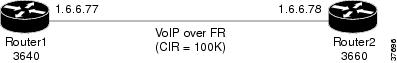
The following output sample shows the PSTN fallback configuration with default fallback values on Router1 for VoIP over Frame Relay as shown in Figure 106. The direction of the calls is from Router1, a Cisco 3640, to Router2, a Cisco 3660. In this example, MD5 authentication is not configured.
Also, SAA responder is configured on Router2 to answer the probes from Router1. When the number 3666 is called from Router1 and congestion is on the link between 10.6.6.77 and 10.6.6.78, the call is not admitted. The user hears a busy tone because there is only one dial peer, 3666, and the IP network that is connected to it is congested. To help avoid this congestion, the call fallback active command is enabled here for PSTN fallback. No other call fallback parameters have been configured.
Figure 106 Network Example for VoIP over Frame Relay
Router(config)# show running-configCurrent configuration:!version 12.2service timestamps debug datetime msec localtimeservice timestamps log uptimeno service password-encryption!hostname Router1!voice-card 3!ip subnet-zerono ip domain-lookup!frame-relay switching!call fallback active!interface Ethernet0/0ip address 10.3.3.77 255.255.0.0no ip directed-broadcast!interface Serial0/0no ip addressno ip directed-broadcastencapsulation frame-relayload-interval 30no keepaliveframe-relay traffic-shapingframe-relay inverse-arp interval 15!interface Serial0/0.1 point-to-pointip address 10.6.6.77 255.255.0.0no ip directed-broadcastframe-relay interface-dlci 100class frs0!interface Ethernet0/1ip address 10.4.4.77 255.255.0.0no ip directed-broadcastload-interval 30!ip classlessip route 0.0.0.0 0.0.0.0 Ethernet0/0ip route 10.5.0.0 255.255.0.0 10.4.4.78ip route 10.255.254.254 255.255.255.255 Ethernet0/0no ip http server!map-class frame-relay frs0no frame-relay adaptive-shapingframe-relay cir 100000frame-relay bc 560frame-relay mincir 100000frame-relay fair-queueframe-relay fragment 100frame-relay ip rtp priority 16384 16383 75!line con 0exec-timeout 35791 0transport input noneline aux 0line vty 0 4password ardlogin!voice-port 1/0/0!voice-port 1/0/1!voice-port 1/1/0!voice-port 1/1/1!dial-peer voice 10 potsdestination-pattern 6666port 1/0/0!dial-peer voice 20 potsdestination-pattern 6777port 1/0/1!dial-peer voice 300 voipdestination-pattern 3...no vadsession target ipv4:10.6.6.78!dial-peer voice 60 potsdestination-pattern 6111port 1/1/0!endCall fallback is not configured on this router. Router2 is a dial peer for Router1, but is not handling calls directly from the PSTN. SAA is configured on Router2 to answer the probes from Router1.
Router(config)# show running-configversion 12.2service timestamps debug uptimeservice timestamps log uptimeno service password-encryption!hostname Router2!voice-card 4!ip subnet-zero!isdn voice-call-failure 0!interface FastEthernet0/0no ip addressno ip directed-broadcastshutdownduplex autospeed auto!interface FastEthernet0/1no ip addressno ip directed-broadcastshutdownduplex autospeed auto!interface Ethernet1/0ip address 10.3.22.80 255.255.0.0no ip directed-broadcast!interface Serial1/0no ip addressno ip directed-broadcastencapsulation frame-relayload-interval 30no keepaliveclockrate 256000frame-relay traffic-shapingframe-relay inverse-arp interval 15!interface Serial1/0.1 point-to-pointip address 10.6.6.78 255.255.0.0no ip directed-broadcastframe-relay interface-dlci 100class frs0!interface Ethernet1/1ip address 10.5.5.74 255.255.0.0no ip directed-broadcast!map-class frame-relay frs0frame-relay fragment 100frame-relay ip rtp priority 16384 16383 75no frame-relay adaptive-shapingframe-relay cir 100000frame-relay bc 1000frame-relay mincir 100000frame-relay fair-queue!voice-port 2/0/0!voice-port 2/0/1!voice-port 2/1/0!voice-port 2/1/1!voice-port 3/0/0!voice-port 3/0/1!voice-port 3/1/0!voice-port 3/1/1!dial-peer voice 10 potsdestination-pattern 3111port 2/0/0!dial-peer voice 20 potsdestination-pattern 3222port 2/0/1!dial-peer voice 100 voipdestination-pattern 6...no vadsession target ipv4:10.6.6.77!dial-peer voice 60 potsdestination-pattern 3999port 3/0/0!dial-peer voice 70 potsdestination-pattern 3888port 3/0/1!saa responder!line con 0exec-timeout 0 0transport input noneline aux 0line vty 0 4login!endConfiguring PSTN Fallback for VoIP over MLP Example
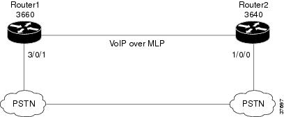
The following output sample configures PSTN fallback for VoIP over MLP for Router1 shown in Figure 107. The direction of the calls is from Router1, a Cisco 3660, to Router2, a Cisco 3640. MD5 authentication is configured. Also, SAA is configured on Router2 to answer the probes from Router1. When the number 6666 is called from Router1 and congestion is on the link between Router1 and Router2, the call is sent to port 3/0/1 and hence to Router2 over the PSTN.
Probes are sent every 20 seconds (default) with 15 packets in each probe, and are sent in the priority queue with the other voice packets after the ip rtp priority command is enabled. Also, the delay and loss threshold command is configured with a delay threshold of 150 milliseconds and a loss threshold of 5 percent, and the cache-aging timeout is 10,000 seconds. The link is configured for 128 kilobits per second (kbps), and 80 kbps is reserved for voice using the ip rtp priority command.
Figure 107 Network Example for VoIP over MLP
Router (config)# show running-configCurrent configuration:!version 12.2service timestamps debug datetimeservice timestamps log datetimeno service password-encryption!hostname Router1!voice-card 4!ip subnet-zero!call fallback probe-timeout 20call fallback threshold delay 150 loss 5call fallback jitter-probe num-packets 15call fallback jitter-probe priority-queuecall fallback cache-timeout 10000call fallback active!interface Multilink1ip address 10.10.10.1 255.255.0.0no ip directed-broadcastno ip route-cacheno ip mroute-cacheno keepalivefair-queue 64 256 0no cdp enableppp multilinkppp multilink fragment-delay 20ppp multilink interleavemultilink-group 1ip rtp priority 16384 16383 80!interface FastEthernet0/0no ip addressno ip directed-broadcastshutdownduplex autospeed auto!interface FastEthernet0/1no ip addressno ip directed-broadcastshutdownduplex autospeed auto!interface Ethernet1/0ip address 10.3.22.80 255.255.0.0no ip directed-broadcast!interface Serial1/0bandwidth 128no ip addressno ip directed-broadcastencapsulation pppno ip route-cacheno ip mroute-cacheload-interval 30no fair-queueclockrate 125000ppp authentication chapppp multilinkmultilink-group 1!interface Ethernet1/1ip address 10.5.5.74 255.255.0.0no ip directed-broadcast!ip classlessip route 0.0.0.0 0.0.0.0 Ethernet1/0ip route 10.4.0.0 255.255.0.0 10.5.5.78ip route 10.255.254.254 255.255.255.255 10.3.0.1no ip http server!voice-port 2/0/0!voice-port 2/0/1!voice-port 2/1/0!voice-port 2/1/1!voice-port 3/0/0!voice-port 3/0/1!voice-port 3/1/0!voice-port 3/1/1!dial-peer voice 10 potsdestination-pattern 3111port 2/0/0!dial-peer voice 20 potsdestination-pattern 3222port 2/0/1!dial-peer voice 60 potsdestination-pattern 3999port 3/0/0!dial-peer voice 70 potsdestination-pattern 6666port 3/0/1!dial-peer voice 200 voipdestination-pattern 6...session target ipv4:10.10.10.1!line con 0exec-timeout 0 0transport input noneline aux 0line vty 0 4exec-timeout 0 0login!endSAA is configured on Router2 to answer the probes from Router1:
Router (config)# show running-configversion 12.2service timestamps debug uptimeservice timestamps log uptimeno service password-encryption!hostname Router2!voice-card 4!ip subnet-zero!isdn voice-call-failure 0!interface FastEthernet0/0no ip addressno ip directed-broadcastshutdownduplex autospeed auto!interface FastEthernet0/1no ip addressno ip directed-broadcastshutdownduplex autospeed auto!interface Ethernet1/0ip address 10.3.22.80 255.255.0.0no ip directed-broadcast!interface Serial1/0no ip addressno ip directed-broadcastencapsulation frame-relayload-interval 30no keepaliveclockrate 256000frame-relay traffic-shapingframe-relay inverse-arp interval 15!interface Serial1/0.1 point-to-pointip address 10.6.6.78 255.255.0.0no ip directed-broadcastframe-relay interface-dlci 100class frs0!interface Ethernet1/1ip address 10.5.5.74 255.255.0.0no ip directed-broadcast!map-class frame-relay frs0frame-relay fragment 100frame-relay ip rtp priority 16384 16383 75no frame-relay adaptive-shapingframe-relay cir 100000frame-relay bc 1000frame-relay mincir 100000frame-relay fair-queue!voice-port 2/0/0!voice-port 2/0/1!voice-port 2/1/0!voice-port 2/1/1!voice-port 3/0/0!voice-port 3/0/1!voice-port 3/1/0!voice-port 3/1/1!dial-peer voice 10 potsdestination-pattern 3111port 2/0/0!dial-peer voice 20 potsdestination-pattern 3222port 2/0/1!dial-peer voice 100 voipdestination-pattern 6...no vadsession target ipv4:10.6.6.77!dial-peer voice 60 potsdestination-pattern 3999port 3/0/0!dial-peer voice 70 potsdestination-pattern 3888port 3/0/1!saa responder!line con 0exec-timeout 0 0transport input noneline aux 0line vty 0 4Local Voice Busyout Configuration Examples
The following example configures digital voice port 0:0.4 on a Cisco MC3810 series concentrator to go into the busyout state if serial interface 0:0 goes out of service:
Router(config)# voice-port 0:0.4Type of VoicePort is FXSrouter(config-voiceport)# busyout monitor interface serial 0:01/2 is in busyout stateRouter(config-voiceport)# endRouter# show voice busyout!If following network interfaces are down, voice port will be put into busyout stateThe following voice ports are in busyout state1/1 is forced into busyout state1/2 is in busyout state caused by Serial0The following example configures digital voice port 2/1:7 on a Cisco 3600 series router to go into the busyout state if serial interface 0:0 goes out of service:
Router(config)# voice-port 2/1:7Type of VoicePort is FXSRouter(config-voiceport)# busyout monitor interface serial 0:01/2 is in busyout stateRouter(config-voiceport)# endRouter# show voice busyout!If following network interfaces are down, voice port will be put into busyout stateThe following voice ports are in busyout state2/1:7 is forced into busyout state2/1:8 is in busyout state caused by Serial0The following example configures the busyout seize action for analog voice port 0/2/1 on a Cisco 3600 series router to repeat:
Router(config)# voice-port 0/2/1Type of VoicePort is FXORouter(config-voiceport)# busyout seize repeatRouter(config-voiceport)# endRouter# show voice busyout!If following network interfaces are down, voice port will be put into busyout stateThe following voice ports are in busyout state0/2/1 is forced into busyout state0/2/2 is in busyout state caused by Serial0The following example forces DS0 timeslots 1 through 12 on controller T1 0 on a Cisco MC3810 multiservice concentrator into the busyout state:
Router(config)# controller t1 0Router(config-controller)# ds0 busyout 1-12Router(config-controller)# endThe following example configures busyout voice class 35, which initiates voice-port busyout whenever either serial port 0 or 1 is in service, and it applies voice class 35 to voice port 1/3:
Router(config)# voice class busyout 35Router(config-voice-class)# busyout monitor serial 0 in-serviceRouter(config-voice-class)# busyout monitor serial 1 in-serviceRouter(config-voice-class)# exitRouter(config)# voice-port 1/3Router(config-voiceport)# voice class 35The following example configures busyout voice class 40, which initiates voice-port busyout whenever an SAA probe sent to both of the two specified remote interfaces results in a link with an ICPIF delay/loss average of more than 15, and it applies voice class 40 to voice port 1/4:
Router(config)# voice class busyout 40Router(config-voice-class)# busyout monitor probe 209.165.202.128 icpif 15Router(config-voice-class)# busyout monitor probe 209.165.202.129 icpif 15Router(config-voice-class)# exitRouter(config)# voice-port 1/4Router(config-voiceport)# voice class 40The following example configures analog voice port 1/1 on a Cisco MC3810 to use an SAA probe with a G.711 alaw profile to probe the link to the remote interface with IP address 209.165.202.128, and to busyout the voice port if the link has a packet loss of more than 50 percent and a packet delay of more than 25 milliseconds:
Router(config)# voice-port 1/1Router(config-voiceport)# busyout monitor probe 209.165.202.128 codec g711a loss 50 delay 25The following example configures voice port 1/0/1 on a Cisco 3600 series router to use an SAA probe with the default (G.711 ulaw) profile to probe the link to the remote interface with IP address 209.165.202.128, and to busyout the voice port if the link has packet loss and delay that exceed the threshold values configured by the call fallback active command:
Router(config)# voice-port 1/0/1Router(config-voiceport)# busyout monitor probe 209.165.202.128The following example configures busyout voice class 60, which configures multiple parameters for voice-port busyout, and it applies voice class 60 to voice ports 1/0/0 and 1/0/1 on a Cisco 3600 series router. The voice ports will busy out under any one the following conditions:
•
•
•
Router(config)# voice class busyout 60Router(config-voice-class)# busyout monitor serial 0/0Router(config-voice-class)# busyout monitor serial 0/1Router(config-voice-class)# busyout monitor serial 1/0 in-serviceRouter(config-voice-class)# busyout monitor serial 1/1 in-serviceRouter(config-voice-class)# busyout monitor probe 209.165.202.128 loss 50 delay 1000Router(config-voice-class)# busyout monitor probe 209.165.202.129 loss 50 delay 1000Router(config-voice-class)# exitRouter(config)# voice-port 1/0/0Router(config-voiceport)# voice class 60Router(config-voiceport)# exitRouter(config)# voice-port 1/0/1Router(config-voiceport)# voice class 60Router(config-voiceport)# exitThe following example configures voice port 1/1 into forced busyout state:
Router(config)# voice-port 1/1Type of VoicePort is FXSRouter(config-voiceport)# busyout forced 00:09:46: port 0 is forced into busyout stateRouter(config-voiceport)# endRouter# show voice busyout!If following network interfaces are down, voice port will be put into busyout state.The following voice ports are in busyout state1/1 is forced into busyout stateThe following example configures voice port 1/2 to busyout monitor mode, monitoring serial 0:
Router(config)# voice-port 1/2Type of VoicePort is FXSRouter(config-voiceport)# busyout-monitor serial 01/2 is in busyout stateRouter(config-voiceport)# endRouter# show voice busyout!If following network interfaces are down, voice port will be put into busyout state.The following voice ports are in busyout state1/1 is forced into busyout state1/2 is in busyout state caused by Serial0The following example configures voice port 1/3 to the busyout seize repeat state:
Router(config)# voice-port 1/3Type of VoicePort is FXOrouter(config-voiceport)# busyout-seize repeatRouter(config-voiceport)# endRouter# show voice busyout!If following network interfaces are down, voice port will be put into busyout state.The following voice ports are in busyout state1/1 is forced into busyout state1/2 is in busyout state caused by Serial0Alarm Trigger for Busyout of Voice Ports Configuration Example
This example creates three permanent trunks on controller T1 0 and configures T1 0 to send a blue (AIS) alarm if all three permanent trunks are OOS. These steps create the voice ports and configure the alarm trigger:
Router(config)# controller t1 0Router(config-controller)# mode casRouter(config-controller)# ds0-group 0 timeslots 1-10 type fxs-ground-startRouter(config-controller)# ds0-group 1 timeslots 11 type fxs-ground-startRouter(config-controller)# ds0-group 2 timeslots 12-23 type fxs-ground-startRouter(config-controller)# alarm-trigger blue 0-2Router(config-controller)# exitRouter(config)#These steps create a voice class to define the trunk conditioning parameters for permanent trunks (in which the default values are not used):
Router(config)# voice class permanent 8
Router(config-class)# signal keepalive 10
Router(config-class)# signal timing oos timeout 60
Router(config-class)# signal timing idle suppress-voice 5
Router(config-class)# signal timing oos restart 120
Router(config-class)# exit
Router(config)#
These steps create a VoIP dial peer to define the network connectivity and trunk conditioning parameters for permanent trunks:
Router(config)# dial-peer voice 100 voipRouter(config-dial-peer)# session target ipv4:172.20.10.10Router(config-dial-peer)# destination-pattern 10..Router(config-dial-peer)# voice-class permanent 8Router(config-dial-peer)# exitRouter(config)#These steps assign each voice port to a permanent trunk and associate each trunk with a network dial peer:
Router(config)# voice-port 0:0Router(config-voiceport)# connection trunk 1001Router(config-voiceport)# exitRouter(config)# voice-port 0:1Router(config-voiceport)# connection trunk 1002Router(config-voiceport)# exitRouter(config)# voice-port 0:2Router(config-voiceport)# connection trunk 1003Router(config-voiceport)# exitRouter(config)#This example configures voice port 0:0 for busyout if serial port 0.1, 0.2, and Ethernet port 0 all go out of service, or serial port 1 comes into service:
Router(config)# voice-port 0:0Router(config-voiceport)# busyout monitor serial 0.1Router(config-voiceport)# busyout monitor serial 0.2Router(config-voiceport)# busyout monitor ethernet 0Router(config-voiceport)# busyout monitor serial 1 in-serviceRouter(config-voiceport)# exitThis example configures voice port 0:1 for busyout if the connections to both of two remote IP addresses are OOS:
Router(config)# voice-port 0:1Router(config-voiceport)# busyout monitor probe 209.165.202.128 codec g711a icpif 15Router(config-voiceport)# busyout monitor probe 209.165.202.129 codec g711a icpif 15Router(config-voiceport)# exitThis example configures voice port 0:2 for busyout under any one of the following conditions:
•
•
•
Router(config)# voice-port 0:2Router(config-voiceport)# busyout monitor serial 0.1Router(config-voiceport)# busyout monitor serial 0.2Router(config-voiceport)# busyout monitor serial 1 in-serviceRouter(config-voiceport)# busyout monitor probe 209.165.202.128 codec g711a icpif 15Router(config-voiceport)# busyout monitor probe 209.165.202.129 codec g711a icpif 15Router(config-voiceport)# exitRouter(config)# exit