-
Cisco IOS Voice, Video, and Fax Configuration Guide, Release 12.2
-
About Cisco IOS Software Documentation
-
Using Cisco IOS Software
-
Voice, Video, and Fax Overview
-
Cisco Voice Telephony
-
Voice over IP Overview
-
Configuring Voice Ports
-
Configuring Dial Plans, Dial Peers, and Digit Manipulation
-
Configuring Quality of Service for Voice
-
H.323 Applications
-
Configuring H.323 Gateways
-
Configuring H.323 Gatekeepers
-
Configuring MGCP and Related Protocols
-
Configuring SIP for VoIP
-
Configuring Voice over Frame Relay
-
Configuring Voice over ATM
-
Configuring Tcl IVR Applications
-
Configuring Debit Card Applications
-
Configuring Settlement Applications
-
Configuring Trunk Connections and Conditioning Features
-
Configuring ISDN Interfaces for Voice
-
Configuring PBX Interconnectivity Features
-
Configuring Fax Applications
-
Configuring Modem Support for VoIP
-
Configuring Video Applications
-
Appendixes
-
Appendix A - Configuring Synchronized Clocking
-
Appendix B - Caller ID
-
Appendix C-Cisco Hoot and Holler over IP
-
Appendix D - Managing Cisco AS5300 Voice Feature Cards
-
Appendix E - Enhanced Voice Services for Japan for Cisco 800 Series Routers
-
Appendix F-Global System for Mobile Communications Full Rate and Enhanced Full Rate Codecs
-
Appendix G - Configuring the Cisco SS7/C7 Dial Access Solution System
-
-
 Feedback
Table Of Contents
Message Delivery Notifications
Fax Relay Packet Loss Concealment
Using Interactive Voice Response
Fax Applications Prerequisites
T.37 Store and Forward Fax Prerequisites
Configuring All Mail Through One Mailer
Configuring Sendmail 8.8.5 for Single Recipients
Fax Relay Packet Loss Concealment Prerequisite Tasks
T.37/T.38 Fax Gateway Prerequisite Tasks
Copying Flash Files to the VFC
Adding Files to the Default File List
Adding Codecs to the Capability List
Deleting Files from VFC Flash Memory
T.38 Fax Relay for VoIP H.323 Prerequisites
Fax Applications Configuration Tasks List
Configuring the On-Ramp Gateway
Configuring the Called Subscriber Number
Verifying the Gateway Configuration
Configuring the Off-Ramp Gateway
Configuring the Transmitting Subscriber Number
Configuring the Fax Transmission Speed
Configuring the Receiving Mail Transfer Agent
Configuring the POTS Dial Peer
Configuring the MMoIP Dial Peer
Configuring the Faxed Header Information
Configuring the Fax Cover Page Information
Verifying the Gateway Configuration
Configuring On-Ramp Gateway Security
Configuring Off-Ramp Gateway Security
Configuring the Gateway Security for TCL Application Files
Verifying the Gateway Security Configuration
Configuring T.37 Store and Forward Fax
Configuring On-Ramp Modem Pooling
Configuring the T.37/T.38 Fax Gateway
Specifying the Interface Type for Fax Calls
Configuring T.38 Fax Relay for VoIP H.323
Fax Applications Configuration Examples
T.37 Store and Forward Fax Configuration Examples
T.37/T.38 Fax Gateway Examples
T.38 Fax Relay for VoIP H.323 Configuration Example
Configuring Fax Applications
This chapter describes T.37 Store and Forward Fax and T.38 Fax Gateway concepts and describes how to configure the fax applications for Cisco AS5300 universal access server access servers. The applications are T.37 Store and Forward Fax, T.38 Fax Relay for Voice over IP (VoIP) H.323, Fax Relay Packet Loss Concealment, and T.37/T.38 Fax Gateways. The applications enable the Cisco AS5300 universal access server to send and receive faxes across packet-based networks, using modems or voice feature cards (VFCs).
This chapter includes the following sections:
•
Fax Applications Prerequisites
•
•
For a complete description of the commands used in this chapter, refer to the Cisco IOS Voice, Video, and Fax Command Reference. To locate documentation of other commands that appear in this chapter, use the command reference master index or search online.
To identify the hardware platform or software image information mentioned in this chapter, use the Feature Navigator on Cisco.com to search for information about the feature or refer to the software release notes for a specific release. For more information, see the "Identifying Supported Platforms" section in the "Using Cisco IOS Software" chapter.
Fax Applications Overview
Fax applications enable Cisco AS5300 universal access servers to send and receive faxes across packet-based networks using modems or VFCs. Some of the benefits of the Fax Gateway are as follows:
•
•
•
•
•
–
–
–
•
The Cisco 2600 and 3600 series routers and Cisco MC3810 multiservice concentrator gateways provide standards-based toll bypass for fax and voice calls. In addition to existing voice and fax toll bypass capabilities, the multiservice gateways provide toll bypass for fax relay with the standards-based ITU-T T.38 fax relay implementation.
On-Ramp Gateway
The Cisco AS5300 universal access server acts as an on-ramp gateway to receive faxes from end users and uses call discrimination to determine call type and destination. It converts the faxes into TIFF files, creates standard Multipurpose Internet Mail Extension (MIME) e-mail messages, attaches the TIFF files to e-mail messages, and forwards the fax-mail messages to the messaging infrastructure of a designated SMTP server, where fax-mail messages are stored.
The on-ramp gateway uses the sending Message Transfer Agent (MTA) and dial peers to receive the faxes. The sending MTA, the Cisco AS5300 universal access server, defines delivery parameters associated with the e-mail message to which the fax TIFF file is attached. These delivery parameters include defining a return e-mail path or designating a destination mail server.
The on-ramp plain old telephone service (POTS) dial peers define the call as a fax transmission and identify the DNIS of the incoming fax call. The on-ramp Multimedia Mail over IP (MMoIP) dial peer defines the destination fax telephone number and the session target, which in this case is the SMTP server.
The configuration of the on-ramp gateway involves the following:
•
•
–
–
–
–
–
–
•
•
–
–
–
–
If DID is enabled, the incoming called number for the on-ramp POTS dial peer should match the destination pattern of the on-ramp MMoIP dial peer. If DID is not enabled, a redialer must be configured and enabled. In this case, the destination pattern must match the forwarded dialed digits from the redialer.
Off-Ramp Gateway
Off-ramp faxing requires that the Cisco AS5300 universal access server act as an off-ramp gateway and dial POTS and communicate with a remote Group 3 fax device using standard fax protocols. It uses call discrimination to determine call type and destination.
Off-ramp faxing activities are not mutually exclusive. An e-mail can be sent as a fax, and a TIFF file can be attached to it. When the Cisco AS5300 universal access server converts the e-mail to fax format, it also converts the attached TIFF file to standard Group 3 fax format.
The off-ramp gateway does the following:
•
•
•
•
The configuration of the on-ramp gateway involves configuring the following:
•
•
•
•
•
•
•
Call Discrimination Process
When the on-ramp gateway receives a call, it immediately identifies whether the call is being delivered using a PRI or T1 channel associated signaling (CAS) interface. If the call is on a T1-CAS interface, the gateway checks the service type field of the CAS group configuration. If the service type of the CAS group is fax, the interface forwards the fax to the MMoIP dial peer. If the gateway determines that the call is on a PRI interface, then the on-ramp gateway looks at several POTS dial peer data fields to determine what kind of call it has received.
POTS Dial Peers
The on-ramp gateway looks at the incoming called number field of each POTS dial peer listed in the dial peer lookup table. It compares the number configured as the incoming called number to the number received and selects the first POTS dial peer whose data matches. If the on-ramp router does not find a match, it assumes that the incoming call is a data call and processes it accordingly.
If the on-ramp router does find a match, it will then look at the service type field of the POTS dial peer to determine whether this is a voice or fax call. If this call has been flagged as a voice call, the on-ramp gateway will process it appropriately as a voice call.
If the call has been flagged as a fax call, the on-ramp gateway checks to see whether DID has been enabled. If DID has been enabled, the gateway concludes that the telephone number it has received is the destination directory number (DN) and forwards the call to be matched with the appropriate on-ramp MMoIP dial peer.
If DID has not been enabled, the on-ramp gateway assumes that the telephone number it received is the access DN. In this case, the on-ramp gateway provides a secondary dial tone and collects another telephone number from the redialer at the other end of the connection that the gateway will use as the destination DN. After the gateway has received this number from the redialer, the number is forwarded and matched to the appropriate on-ramp MMoIP dial peer.
A redialer is an interface hardware device that connects a fax device to the PSTN network. The user enters the complete telephone number into the fax device and the attached redialer captures and stores those dialed digits. It dials the on-ramp Cisco AS5300 universal access server that provides a secondary dial tone. Use a redialer when one of the following is true:
•
•
•
The redialer should be programmed to wait two seconds and then send the PIN with destination digits to the on-ramp gateway.
The fax protocol starts after 52 digits have been detected or the interdigit timeout has exceeded 5 seconds. If the debug fax receive command is enabled, the digits are displayed as received by the on-ramp gateway. If a dial peer is matched, the fax proceeds. If a dial peer is not matched, the fax fails.
By default, DID is disabled, which means that the on-ramp gateway assumes that the fax call was placed using a redialer. When the call arrives, the gateway collects digits until it can identify the destination. Once the destination is identified, the gateway forwards the call to the next call leg (MMoIP dial peer).
If DID is enabled, the on-ramp gateway uses the called number (DNIS) to find a dial peer for the outgoing call leg. DID enables the gateway to match the incoming called number with a dial peer and then directly place the outbound call. With DID, the server does not present a dial tone to the fax machine and does not collect digits. It forwards the call directly to the configured destination.
The off-ramp gateway looks at the destination-pattern field of each POTS dial peer listed in the dial peer lookup table. It compares the number configured as the destination pattern with the destination DN portion of the fax-mail address and selects the first match.
After the off-ramp gateway has identified the appropriate POTS dial peer, it matches call type information. If the call type is identified as fax, it forwards the fax-mail message to off-ramp services. If the off-ramp router does not find a match, the recipient identified by the given address is not accepted by the off-ramp router.
MMoIP Dial Peers
The MMoIP function in the call discrimination process determines the fax-mail destination, which is the off-ramp gateway over which the fax-mail is sent to the destination fax machine. The on-ramp gateway looks at the destination pattern field of each MMoIP dial peer listed in the dial peer lookup table. It compares the number configured as the destination pattern with the number received and selects the first MMoIP dial peer whose the data matches.
The on-ramp gateway then looks at the session target field for the selected MMoIP dial peer in order to identify the destination of the fax-mail message. This value could be a specific off-ramp gateway or, if the fax is being delivered as an e-mail message, an e-mail address for a specific mail server.
The resolution of a fax image can be increased or decreased using the MMoIP dial peer configuration. Pass-through is the default: the image is sent exactly as it is received. Depending on the capacity of the fax machines in the network, a different image encoding (compression) scheme could be required for the fax TIFF image. The encoding default is pass-through.
On-Ramp Gateway Security
On-ramp gateway security controls who can send fax messages to the network. It is facilitated by authentication, authorization, and accounting (AAA) security services using RADIUS or TACACS+ as the local security protocol. On-ramp gateway faxing is a client of the authentication server, whether it is RADIUS or TACACS+. User information is forwarded to the AAA interface, and the authentication request is forwarded to the security server.
Authentication must be completed before the first page of faxed material is accepted from the modem by the Fax Application Process (FAP). If a response is not received from the AAA server before the first page is received, the fax modem or voice feature card (VFC) disconnects the call.
The on-ramp gateway inserts whatever value was configured in the "X-account-ID" field of the e-mail header that is used for authentication and accounting by the on-ramp gateway.
Attribute-Value Pairs for AAA
RADIUS attributes define specific AAA elements in a user profile, which is stored on the RADIUS server. The Cisco implementation of RADIUS supports Internet Engineering Task Force (IETF) and vendor-proprietary attributes. IETF RADIUS attribute 26 enables vendors to support extended attributes not suitable for general use. The Cisco fax applications use the RADIUS implementation of vendor-specific options in the recommended format.
Table 50 lists the supported vendor-specific options (subtype numbers from 3 through 21) using IETF RADIUS attribute 26 and the Cisco vendor-ID company code of 9.
Access Control Lists
Incoming Access Control Lists (ACLs) can be used on Ethernet or FastEthernet interfaces to filter SMTP fax traffic. It is recommended that ACLs be configured to restrict access to the SMTP port (port 25) to only trusted e-mail servers. Creating ACLs is beyond the scope of this document. For information, refer to the Cisco IOS Security Configuration Guide.
ESMTP Accounting Services
Accounting information can be collected about fax services in two ways:
•
•
The extended simple mail transfer protocol (ESMTP) accounting feature enables the collection of accounting information as part of the SMTP session. This functionality is activated through the use of an intelligent fax client or MTA. In ESMTP accounting, the off-ramp gateway acting as an ESMTP server advertises capabilities to the MTA, which is acting as an e-mail client.
One of the capabilities the off-ramp gateway advertises is "xaccounting," which supports ESMTP accounting. If the MTA recognizes the xaccounting service extension, the MTA (acting as the client) accepts the ESMTP accounting information sent from the off-ramp gateway. If the MTA does not recognize the xaccounting service extension, it does not send the xact command to the off-ramp gateway. In that case, the off-ramp gateway does not respond with ESMTP accounting data.
To use SMTP to collect accounting data, the MTA must be configured to explicitly request accounting information as part of the e-mail session. The MTA must be able to do the following:
•
•
Message Delivery Notifications
Described in RFC 2298, an message delivery notification (MDN) is a message that is sent to the originator of an e-mail message indicating that the e-mail message was received. MDN elements must be configured for both the on-ramp and off-ramp gateways. MDN requests as part of the on-ramp MMoIP dial peer configuration must be enabled. For complete instructions on how to configure MDNs, see the "Configuring MDNs" section.
Delivery Status Notifications
Delivery status notifications (DSNs) are messages or responses that are automatically generated and sent to the sender or originator of an e-mail message by the SMTP server, notifying the sender of the status of the e-mail message. DSNs must be configured for both the on-ramp and off-ramp gateways.
Three different states can be reported back to the sender as follows:
•
•
•
Because the delivery states are not mutually exclusive, messages for all or any combination of these events can be generated.
DSN requests can be enabled as part of the on-ramp MMoIP dial peer configuration. For complete instructions on how to configure DSNs, refer to the "Configuring DSNs" section.
T.37 Store and Forward Fax
T.37 Store and Forward Fax is an implementation of the RFC 2305 proposed standard from the IETF and is the same as the T.37 recommendation of the International Telegraph Union (ITU). T.37 Store and Forward Fax enables the access server to become a multiservice platform, supplying both data and fax communication using modems.
T.37 Store and Forward Fax enables the following:
•
•
•
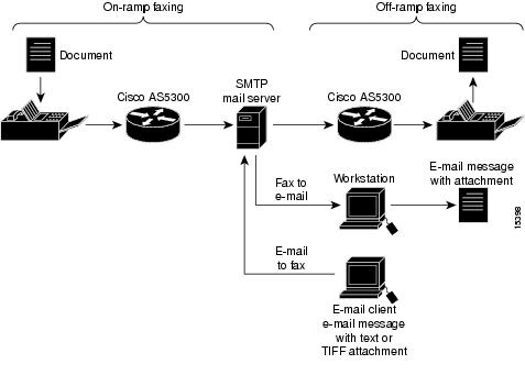
The basic functionality is facilitated through SMTP with additional functionality that provides confirmed delivery using existing SMTP mechanisms, such as ESMTP. Figure 117 shows a simple network topology using T.37 Store and Forward Fax.
Figure 117 T.37 Store and Forward Fax Functionality
The messaging infrastructure performs message routing, storage, and transport, and can be a standard Internet MTA—for example, UNIX sendmail or custom T.37 Store and Forward Fax software. The responsibility of delivering the fax-mail message falls to SMTP and the mail server.
Modem Pooling
As a default, T.37 Store and Forward Fax receives faxes on modems that are in the on-ramp gateway default modem pool. These modems are available for both fax and data calls. The on-ramp gateway determines the call type using DNIS and compares the DNIS number to the configured value for the incoming called-number POTS dial-peer configuration command.
If the DNIS number matches the incoming called number, DNIS treats the call as a fax transmission. If it does not find a match in its dial peer lookup table, it treats the call as a data call.
The incoming fax calls can be configured to bypass the default modem pool by defining a named modem pool. This is particularly useful if the calls have Modem ISDN channel aggregation (MICA) and Microcom faxes, because it diverts fax traffic from MICA modems that do not support fax transmission.
Fax Relay Packet Loss Concealment
Fax relay packet loss concealment improves the current real-time fax over IP (commonly known as fax relay) implementation in Cisco gateways, enabling fax transmissions to work reliably under higher packet loss conditions.
In addition, this feature includes enhanced real-time fax debug capabilities and statistics for improved field diagnostics and troubleshooting. The capabilities and statistics give better visibility into the real-time fax operation in the gateway.
One improvement is fax relay Error Correction Mode (ECM) on the VoIP dial peer. When used, the DSP fax relay firmware disables ECM through modification of the DIS T.30 message in both directions.
ECM provides for error-free page transmission. It is available on fax machines that include memory for storage of the page data (usually high-end fax machines). The page is transmitted in a series of blocks. After receiving the complete page data, the receiving fax indicates any frames with errors. The transmitting fax then retransmits those frames. This process is repeated until all frames have been received without errors. If the receiving fax is not able to receive an error-free page, the fax transmission may fail, and one of the fax machines may disconnect. With packet-loss levels greater than 2 percent, fax transmissions consistently fail between page transmissions when ECM is enabled.
When ECM is disabled, the page is sent using high-speed modulation in its raw encoded format. When detecting line errors with ECM disabled, the receiving fax has three options (in order of severity):
•
•
•
Note
Handling of Enclosures
All Cisco fax applications can process e-mail with the following MIME media content types:
•
•
•
Further, all Cisco fax applications support the following content transfer encodings:
•
•
•
•
These content transfer encodings can be wrapped in any multipart/* content type. When messages with multiple sections are received, the first part of the multipart message is processed, and a count of what is and is not successfully sent is stored. The rest of the message is discarded. For example, if a multipart, alternative message has a plain text part and an enriched, html text part and the plain text is first, the the plain text part is the only part processed.
Note
Caution
T.37/T.38 Fax Gateway
When the Cisco AS5300 universal access server is equipped with VFCs, it supports carrier-class Voice over IP (VoIP) and Fax over IP services. Since the Cisco AS5300 universal access server is H.323 compliant, it supports a family of industry-standard voice codecs and provides echo cancellation and voice activity detection (VAD)/silence suppression.
The VFC is a coprocessor card with a powerful reduced instructions set computing (RISC) engine and dedicated, high-performance DSPs to ensure predictable, real-time voice processing. The design enables streamlined packet forwarding. The Cisco AS5300 universal access server supports two VFCs that are scalable up to 96 E1 or 120 T1 voice connections within a single chassis.
T.37 Store and Forward Fax was supported by modem cards while the voice applications ran on the C542 digital signal processing module (DSPM) and C549 DSPMs that populated Cisco AS5300 VFCs. Each type of call required different technologies. With this software release, a single DSPM technology supports the following:
•
•
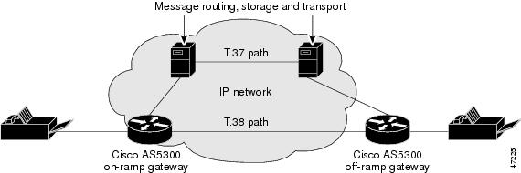
Figure 118 highlights the real-time (T.38 path) versus the T.37 Store and Forward processing (T.37 path) for fax transactions over IP networks.
Figure 118 Real-Time Versus T.37 Store and Forward Fax Processing
Fax over IP used a proprietary protocol and an H.323 connection, represented by the T.37 path in the diagram. The T.37 path used the ESMTP T.37 Store and Forward method. The on-ramp gateway router accepted fax data from the PSTN fax machine.
The fax data was converted into a TIFF attachment in a MIME e-mail message and transmitted to a T.37 Store and Forward SMTP server. The server would deliver the fax-mail message to the off-ramp gateway. Once the off-ramp gateway received the fax-mail message, it processed the message and initiated a session with the destination fax machine.
With this software release, the T.38 path takes precedence over the T.37 path whenever possible. This means that as a fax session is being set up, the sending gateway first communicates using the T.38 path. If the communication fails, the sending gateway rolls over to the Cisco T.37 path if it is configured to rollover.
Using Interactive Voice Response
Interactive voice response (IVR) applications control calls by using voice prompts and digit collection in order to authenticate the user and identify the call destination. The applications are assigned to specific ports or invoked based on DNIS. They accommodate many gateway services by customizing the presentation of the interfaces to callers.
IVR uses Tool Command Language (TCL) scripts to gather information. For example, a TCL script plays when the caller receives a voice prompt to enter a specific type of information, such as a PIN. After the caller inputs the PIN, TCL collects the digits and forwards the digits to the server for storage and retrieval.
T.38 Fax Relay for VoIP H.323
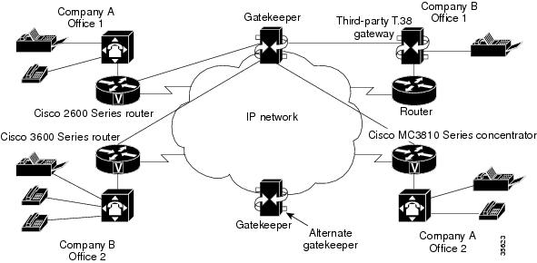
The T.38 Fax Relay for VoIP H.323 feature provides standards-based fax relay protocol support on the Cisco 2600 and 3600 series routers and the Cisco MC3810 multiservice concentrator gateways. The Cisco proprietary fax relay solution is sometimes not an ideal solution for Enterprise and Service Provider customers who have implemented a mixed-vendor network. Because the T.38 fax relay protocol is standards based, Cisco gateways and gatekeepers can interoperate with third-party T.38-enabled gateways and gatekeepers in a mixed-vendor network when real-time fax relay capabilities are required.
shows an IP H.323 network with Cisco and third-party gateways and gatekeepers using T.38 fax relay functionality. By using T.38 fax relay, all gateways and gatekeepers in this network are able to send faxes to other remote offices or to the offices of another company on the IP network.
Figure 119 IP Network for T.38 Fax Relay
For example, when a fax is sent from the originating gateway, a voice call is established. The terminating gateway detects the fax tone generated by the answering fax machine. The VoIP H.323 call stack then starts a T.38 mode request using H.245 procedures. If the opposite end of the call acknowledges the T.38 mode request, the initial audio channel is closed and a T.38 fax relay channel is opened. When the fax transmission is completed, the call reverts to voice mode.
Fax Applications Prerequisites
The following sections describe prerequisite tasks to perform before configuring all of the available fax applications:
•
•
•
•
Note
T.37 Store and Forward Fax Prerequisites
Before the T.37 Store And Forward Fax can be configured, the following tasks are required:
•
–
–
•
•
–
–
–
–
For more information about any of the these configuration tasks, refer to the Cisco AS5300 Universal Access Server Software Configuration Guide.
Note
The following sections describe specific prerequisite tasks to configure T.37 Store and Forward Fax:
•
•
Configuring the SMTP Server
Note
Although it is not required, configuring the SMTP server enhances functionality. To configure the SMTP server, perform the following tasks:
•
–
•
Fax transmission has delivery requirements that are different from those of e-mail transmission. For example, in certain countries, it is illegal to try to send a fax more than three times in a row if transmission fails.
SMTP mail delivery requirements are not governed by such strict regulations. In general, if an e-mail message cannot be delivered, the SMTP server is supposed to continue trying every 30 minutes for up to 5 days. To avoid any complications arising from the difference between the SMTP e-mail and fax delivery requirements, modify the following parameters:
–
–
–
–
Configuring the MTAs
MTAs, such as sendmail, Post.Office, and others, are normally configured to provide fast and reliable service for transferring e-mail. However, the needs of fax users are different. The best example of differing fax requirements is retry timeouts.
A typical MTA configuration will retry sending failed message transmissions every 30 minutes for up to 5 days. Resending e-mail every 30 minutes is usually unacceptable to fax users—they want retries more often than every 30 minutes and usually want transmission aborted well before the typical 5-day retry limit. Although a typical unmodified MTA can be used with the Cisco AS5300 universal access server for off-ramp operations, the MTA may need to be fine-tuned for fax operation.
Configuring Fax Operation
The Cisco AS5300 universal access server off-ramp accepts only one e-mail recipient per SMTP transaction because the SMTP server does not do the following:
•
•
The Cisco AS5300 universal access server prevents one SMTP transaction from going to multiple recipients by responding to the second and subsequent RCPT commands with a "450" reply code. Because of the typical mailer configuration, this causes a 30-minute delay for each recipient: immediate delivery for the first recipient, 30-minute delay for the second recipient, 60-minute delay for the third recipient, etc.
Configuring All Mail Through One Mailer
To simplify system administration, have all mail to the Cisco AS5300 universal access server go through one mailer by setting up a DNS MX record for the Cisco AS5300 universal access server. The record points to and sets up the mailer to skip MX record processing for the Cisco AS5300 universal access server. For example, the following two records would exist in DNS:
sj-offramp in mx 10 sj-mailersj-offramp in mx 20 sj-offrampsj-offramp in a 1.2.3.4Configure ACLs to block incoming mail from other mailers. This prevents unauthorized use of the fax off-ramp and forces all mail to go through one mailer.
If ACLs have been set up on the router, the second MX record should not be placed in the DNS. For more information about ACLs, refer to the Cisco IOS Security Configuration Guide.
Configuring Sendmail 8.8.5 for Single Recipients
Fine-tuning sendmail 8.8.5 for a single recipient enables the Cisco AS5300 universal access server to work faster with Store and Forward Fax off-ramps and reduce delays caused by attempting to send to multiple recipients. It is important that sendmail be configured to send to each recipient serially, but without a delay after each transmission. Parallel configuration of sendmail with a single recipient and multiple sendmail client processes would cause a single message to be returned through sendmail, perhaps on a different port. The parallel configuration is not within the intended scope of this document.
Caution
To configure sendmail 8.8.5 to send to a single recipient, perform the following tasks:
•
Kmailertable hash /etc/mailertable
Note
•
# not local -- try mailer table lookupR$* <@ $+ > $* $: < $2 > $1 < @ $2 > $3 extract host nameR< $+ . > $* $: < $1 > $2 strip trailing dotR< $+ > $* $: < $(mailertable $1 $) > $2 lookupR< error : $- $+ > $* $#error $@ $1 $: $2 check -- error?R< $- : $+ > $* $# $1 $@ $2 $: $3 check -- resolved?R< $+ > $* $: $>90 <$1> $2 try domain
Note
If the mailer table cannot be found, place the lines in Ruleset 0, which starts at the line containing "S0," before the rules that deliver local mail (R$=L $#local ...).
•
Mfaxofframp, P=[IPC], F=DFMuXa0, S=11/31, R=21, E=\r\n, L=2040,T=DNS/RFC822/SMTP,A=IPC $hEnsure that the S and R values are the same as those for the existing mailer specifications for mail relaying. The existing S and R values are the lines beginning with an uppercase "M," usually toward the end of the sendmail.cf file.
The S and R values control sendmail rewrite rules as applied to the Sender and Recipient addresses of the message. The rules and rule numbers must be different on each system, especially at sites that have complex sendmail configurations.
It is important to omit the "F=m" flag and include the "F=0" (zero) flag as shown. The "m" flag causes delivery to multiple recipients (which is unwanted) and the "0" (zero) flag disables MX lookups (which are desired). The "0" (zero) flag is available only in sendmail version 8.8 or later. If an earlier version of sendmail is configured, omit the "0" and use [ ] in the mailer table.
•
offramp-seattle.cisco.com faxofframp:offramp-seattle.cisco.comas5300-denver.cisco.com faxofframp:as5300-denver.cisco.comIf prior version of sendmail 8.8 is configured, use brackets around the right-side host name as follows:
offramp-seattle.cisco.com faxofframp:[offramp-seattle.cisco.com]•
/usr/sbin/makemap hash /etc/mailertable.db < mailertable.txt
Note
•
ps -e | grep sendmailkill pid # using PID indicated by above output/usr/lib/sendmail -bd•
as5300-hostname in a a.b.c.din mx 10 sendmail-systemin mx 20 as5300-hostnameThis causes mail to be delivered to the sendmail-system first. Because the sendmail configuration disables MX lookups ("F=0") for the Cisco AS5300 universal access server, sendmail delivers directly to the IP address of the Cisco AS5300 universal access server. Also, if the sendmail system is down or otherwise unavailable, mail is queued directly to the Cisco AS5300 universal access server. Alternatively, use the following configuration:
as5300-hostname in a a.b.c.din mx 10 sendmail-systemin mx 20 backup-mtaIn this example, backup-mta is another sendmail (or other) mailer.
•
–
–
–
–
–
–
–
•
Note
Configuring the Redialers
Perform the following tasks to enable a redialer:
•
•
Note
Fax Relay Packet Loss Concealment Prerequisite Tasks
VCWare 7.04 or higher version must be running before configuring fax relay packet loss concealment.
T.37/T.38 Fax Gateway Prerequisite Tasks
To enable the T.37/T.38 Fax Gateway for the Cisco AS5300 universal access server, perform the following tasks:
•
•
•
•
•
Downloading VCWare to the VFC
VFCs for the Cisco AS5300 universal access server come with a single bundled image of VCWare stored in VFC Flash memory. Table 51 shows the extension types defined for these embedded firmware files.
DSPWare is stored as a compressed file within VCWare. VCWare must be unbundled to install DSPWare in Flash memory. During the unbundling process, two default lists (default file and capability) are automatically created, populated with default files from that version of VCWare, and stored in VFC Flash memory. The default file list contains the names of the files that are initially loaded into DSP upon boot up, and the capability list defines the set of codecs that can be negotiated for a voice call.
VFC management enables the following functionality:
•
•
•
•
Before downloading VCWare to the VFC, determine whether or not the version of VFC ROM Monitor software is compatible with the installed Cisco IOS image. VFC ROM version 1.2 requires Cisco IOS image 0.14.1 (1.6 NA1) or later. VFC ROM Monitor version 1.2 can be made to work with Cisco IOS image 0.13 (or later) by appending the suffix ".VCW" to the VCWare image stored in VFC Flash memory.
The required tasks are as follows:
•
•
•
Determining the Number of VFCs
To determine the number of installed VFCs and their location, use the following command in privileged EXEC mode:
Determines the number of installed VFCs and their location.
For each VFC identified and located, upgrade the system software on that VFC.
Identifying the VFC Mode
To identify the mode (whether VCWare or ROM Monitor), use the following command in privileged EXEC mode:
Determines whether the VFC is operating in VCWare mode or ROM Monitor mode.
If the mode is VCWare, the VFC status will be "VCWARE running." If the mode is ROM monitor, the VFC status will be "ROMMON."
Downloading the Software in VCWare Mode
To download VFC software to the VFC while in VCWare mode, use the following commands in privileged EXEC mode:
The Cisco AS5300 universal access server must be rebooted before these changes can take effect.
Note
Downloading the Software in ROM Monitor Mode
To download VFC software while in ROM monitor mode, use the following commands in privileged EXEC mode:
The Cisco AS5300 universal access server must be rebooted before these changes can take effect.
Note
Copying Flash Files to the VFC
Each VFC comes with a single bundled image of VCWare stored in Flash memory. VoIP for the Cisco AS5300 universal access server enables two different ways to copy new versions of VCWare to the VFC Flash memory by:
•
•
Downloading from the Cisco AS5300 Motherboard
To download from the AS5300 motherboard to Flash memory, use the following commands in privileged EXEC mode:
Downloading from a TFTP Server
To download the latest version of VCWare from a TFTP server, ensure that the file is stored on the TFTP server. If a copy of the current version of VCWare is resident on disk, store that image on a TFTP server or the file cannot be downloaded into VFC memory. To copy the Flash file from a TFTP server, use the following commands in privileged EXEC mode:
Unbundling VCWare
VCWare must be unbundled before DSPWare can be loaded in Flash memory. The default file and capability lists are created and populated with the appropriate default files for that version of DSPWare. Table 52 shows the files associated with each firmware file.
To unbundle the current running image of VCWare, use the following command in privileged EXEC mode:
Adding Files to the Default File List
After the VCWare is unbundled, the default file list is automatically created and populated with the default files for VCWare. The default file list indicates which files are initially loaded into DSP at boot up. The following example shows the output from the show vfc def command, which displays the contents of the default file list:
Router# show vfc 1 defDefault List for VFC in slot 1:1. btl-vfc-1.0.13.0.bin2. cor-vfc-1.0.1.bin3. bas-vfc-1.0.1.bin4. cdc-g729-1.0.1.bin5. fax-vfc-1.0.1.bin6. jbc-vfc-1.0.13.0.binUnder most circumstances, these default files should be sufficient. If needed, files from those stored in VFC Flash memory can be added to the default file list or existing files replaced from the default file list. When a specific file is added to the default file list, it replaces the existing file with the same extension type.
To add a file to the default file list, use the following command in global configuration mode:
Selects a file stored in the Flash memory to be added to the default file list.
Adding Codecs to the Capability List
The capability list defines the set of codecs that can be negotiated for a voice call. Like the default file list, the capability list is created and populated when VCWare is unbundled and DSPWare added to VFC Flash memory. The following example shows the output from the show vfc cap command, which displays the contents of the capability list:
Router# show vfc 1 capCapability List for VFC in slot 1:1. fax-vfc-1.0.1.bin2. bas-vfc-1.0.1.bin3. cdc-g729-1.0.1.bin4. cdc-g711-1.0.1.bin5. cdc-g726-1.0.1.bin6. cdc-g728-1.0.1.bin7. cdc-gsmfr-1.0.1.binCodec files can be added, using VFC management, if needed for a specific telephony network.
Note
To add a codec overlay file to the capability list, use the following command in global configuration mode:
Selects a codec overlay file to be added to the capability list.
Deleting Files from VFC Flash Memory
In some instances, a file may need to be deleted from the default file or capability lists. To delete a file from VFC Flash memory, use the following command in privileged EXEC mode:
Erasing the VFC Flash Memory
When upgrading the Cisco AS5300 universal access to a more current version of VCWare, new files are stored in VFC Flash and do not overwrite existing files. The contents of VFC Flash memory must be erased to free memory space. To erase the Flash memory of a specific VFC, use the following command in privileged EXEC mode:
Configuring IVR
Before configuring the Cisco gateways to support IVR, perform the following tasks:
•
•
•
•
–
–
•
•
T.38 Fax Relay for VoIP H.323 Prerequisites
Ensure that the following have been performed or checked before configuring VoIP H.323 for the T.38 fax relay:
•
•
•
•
Note
Fax Applications Configuration Tasks List
The configuration tasks for fax applications are described in the following sections:
•
•
•
•
Configuring the On-Ramp Gateway
To configure the on-ramp gateway, perform the tasks described in the following sections:
•
•
•
•
Note
Configuring the Called Subscriber Number
To configure the called subscriber number, use the following commands in global configuration mode:
Configuring the Sending MTA
Defining the originator of the e-mail fax, the destination mail server, the subject of the message, and the postmaster, which is the default mail station for undeliverable e-mail message, is required (Steps 1 through 5). Steps 6 and 7 are optional.
Note
To configure the sending MTA, use the following commands in global configuration mode:
Configuring POTS Dial Peers
To configure the on-ramp gateway POTS dial peers, use the following commands beginning in global configuration mode:
Note
Configuring MMoIP Dial Peers
To configure the on-ramp gateway MMoIP dial peers, use the following commands beginning in global configuration mode:
Verifying the Gateway Configuration
To verify the gateway configuration, perform the following tasks:
•
•
•
•
•
•
•
•
Configuring the Off-Ramp Gateway
To configure the off-ramp gateway, perform the tasks in the following sections:
•
•
•
•
•
•
•
Configuring the Transmitting Subscriber Number
To configure the transmitting subscriber number, use the following command in global configuration mode:
Configuring the Fax Transmission Speed
To configure the fax transmission speed, use the following command in global configuration mode:
Specifies the maximum fax speed.
Configuring the Receiving Mail Transfer Agent
To configure the receiving MTA, use the following commands in global configuration mode:
Configuring the POTS Dial Peer
To configure the POTS dial peer for the off-ramp gateway, use the following commands beginning in global configuration mode:
Configuring the MMoIP Dial Peer
To configure the off-ramp gateway MMoIP dial peer, use the following commands beginning in global configuration mode:
Note
Configuring the Faxed Header Information
Because the off-ramp gateway does not alter fax TIFF attachments, the header information cannot be configured for faxes being converted from TIFF files to standard fax transmissions.
To configure faxed header information, use the following commands in global configuration mode:
Configuring the Fax Cover Page Information
Because the off-ramp gateway does not alter fax TIFF attachments, the cover pages cannot be configured for faxes being converted from TIFF files to standard fax transmissions.
To configure fax cover page information, use the following commands in global configuration mode:
Verifying the Gateway Configuration
To verify the gateway configuration, perform the following tasks:
•
•
•
•
•
•
•
•
Configuring Gateway Security
To configure gateway security, perform the tasks in the following sections:
•
•
•
Configuring On-Ramp Gateway Security
To configure on-ramp security, use the following commands in global configuration mode:
Configuring Off-Ramp Gateway Security
Note
To configure off-ramp security, use the following commands in global configuration mode:
Configuring the Gateway Security for TCL Application Files
To configure gateway security for the TCL application files that are used for fax calls on the T.37/T.38 Fax Gateway with a VFC, use the following commands in global configuration mode:
Verifying the Gateway Security Configuration
To verify the gateway security configuration, perform the following tasks:
•
•
•
Configuring MDNs
Note
To configure the on-ramp gateway to support MDN, use the following commands beginning in global configuration mode:
To configure the off-ramp gateway to support MDN, use the following command in global configuration mode:
Router(config)# mta receive generate-mdn
Specifies that the Cisco AS5300 universal access server acting as the off-ramp gateway will respond to a request for an MDN.
Verifying MDN Configuration
To verify the MDN configuration, perform the following tasks:
•
•
•
•
Configuring DSNs
Note
To configure DSN, use the following commands beginning in global configuration mode:
Verifying DSN Configuration
To verify the DSN configuration, perform the following tasks:
•
•
•
•
•
Configuring T.37 Store and Forward Fax
The Cisco AS5300 universal access server supports only two modem cards: the Microcom modem card and the MICA technologies modem card. Microcom modem cards support both on-ramp and off-ramp fax activities. MICA technologies modem cards support only off-ramp faxing.
Store and forward fax on-ramp has been designed to work by using direct inward dial (DID) or a redialer. A redialer is a hardware interface device that interconnects between a fax device and the PSTN. If DID is disabled, a redialer must be configured and enabled on the originating fax machine before Store and Forward Fax is operational.
To configure the T.37 Store and Forward Fax application, configure the on- and off-ramp gateways, including gateway security, and perform the following tasks:
•
•
Configuring On-Ramp Modem Pooling
To configure on-ramp modem pooling, use the following commands in global configuration mode:
Step 1
Router(config)# modem-pool name
Creates a modem pool.
Step 2
Router(config)# pool-range number-number
Assigns a range of modems to the specified modem pool.
Configuring ECM
To configure ECM, use the following commands beginning in global configuration mode:
Configuring the T.37/T.38 Fax Gateway
The Cisco AS5300 universal access server must be equipped with 128 MB of RAM in the following situations:
•
•
To configure the T.37/T.38 Fax Gateway feature, configure the on- and off-ramp gateways, including gateway security and perform the following tasks:
•
•
•
Specifying the Interface Type for Fax Calls
To select the interface type (modem or VFC), use the following command in global configuration mode:
Configuring IVR Functionality
Note
To configure IVR functionality, use the following commands beginning in global configuration mode:
Table 53 lists the TCL scripts required for fax applications on VFCs.
Verify the IVR Configuration
To verify the IVR configuration, perform the following tasks:
•
•
•
•
Configuring T.38 Fax Relay for VoIP H.323
Only User Datagram Protocol (UDP) is implemented for T.38 Fax Relay for VoIP H.323 gateway support on the multiservice gateways. Transmission Control Protocol (TCP) T.38 Fax Relay is not supported. For further information on T.38 protocol, refer to ITU-T Recommendation.
Voice interoperability testing with third-party gateways and gatekeepers must be completed before configuring the T.38 Fax Relay for VoIP H.323 in the network because different companies are allowed to select certain parts of H.323 and T.38 to implement into their gateways and gatekeepers.
T.38 Fax Relay interoperability requires H.323 Version 2. In addition, T.38 Fax Relay is not supported in the following:
•
•
•
Configure both the on-ramp and off-ramp gateways to enable T.38 Fax Relay for VoIP H.323. To specify the global default fax protocol for all the VoIP dial peers, use the global configuration mode. To specify the fax protocol for a specific VoIP dial peer, which takes precedence over the global configuration, use dial-peer configuration mode.
Configuring T.38 Fax Relay for VoIP H.323 Globally
To configure T.38 Fax Relay for VoIP H.323 for all the connections of a gateway, which is required, use the following commands beginning in global configuration mode:
Configuring T.38 Fax Relay for a Specific Dial Peer
To configure T.38 Fax Relay for VoIP H.323 for a specific dial peer, which is optional, use the following commands beginning in global configuration mode:
Verifying T.38 Fax Relay for VoIP H.323
To verify the T.38 fax relay for VoIP H.323, perform the following tasks:
•
•
Troubleshooting Tips
To troubleshoot the T.38 Fax Relay for VoIP H.323 feature, perform the following steps:
•
•
•
•
•
Monitoring and Maintaining T.38 Fax Relay for VoIP H.323
To monitor and maintain the T.38 fax relay for VoIP H.323, perform the following tasks:
•
•
Fax Applications Configuration Examples
Configuration examples are provided in the following sections:
•
•
T.37 Store and Forward Fax Configuration Examples
The following output sample is the configuration of a Cisco AS5300 universal access server acting as an on-ramp gateway in global configuration mode:
!Define the called subscriber number. In this case, the number configured as the!destination pattern will be used as the called subscriber identifier.fax receive called-subscriber $d$!!Specify the originator of the e-mail address. In this case, the originator information!is derived from the calling number.mta send mail-from username $s$!!(Optional) Provide additional information about the sending device. In this example,!the sending device's hostname is alabamamta send origin-prefix alabama!!Define where this fax-mail should be delivered (which is the mail server postmaster!account) if it cannot be delivered to the defined destination.mta send postmaster postmaster@company.com!!(Optional) If configuring MDNs, specify the address where they should be!sent.mta send return-receipt-to username postmaster@company.com!!Specify the destination e-mail server that accepts on-ramp fax-mail.mta send server california.fax.com!!Define the text string that will be displayed as the subject of the fax-mail.mta send subject Fax-Mail Message!!!Enter dial-peer configuration mode and define an on-ramp POTS peer.dial-peer voice 1000 pots!!Designate fax as the type of information handled by this dial peer.information-type fax!!Specify direct inward dial for this dial peer.direct-inward-dial!!Define the incoming called number associated with this dial peerincoming called number 5105551212!!(Optional) Define the maximum number of connections that will be used simultaneously!to transmit fax-mail.max-conns 10!!!Define an on-ramp MMoIP dial peer.dial-peer voice 1001 mmoip!!Define the telephone number associated with this dial peer.destination-pattern 14085554321!!Define a destination e-mail address for this dial peersession-target mailto:$d$@abccompany.com!!(Optional) Request that DSNs be sent.dsn!!Specify a particular image encoding method to be used for fax images. In this!example, Modified Huffman (IETF standard) is being specified.image encoding mh!!Specify a particular fax image resolution. In this example, the image resolution was!set to 204 by 196 pixels per inch (fine).image resolution fine!!Designate fax as the type of information handled by this dial peer.info-type fax!!(Optional) Define the maximum number of connections that will be used simultaneously!to transmit fax-mail.max-conn 10!!(Optional) Request that MDNs be sent.mdn!!Specify SMTP as the protocol to be used for Store and Forward Fax.session protocol smtpThe following output sample is the configuration of a Cisco AS5300 universal access server acting as the off-ramp gateway beginning in global configuration mode:
!Define the transmitting subscriber number (TSI); this is the number that is!displayed in the LCD of the receiving fax machine. In this example, the sender's!name, captured by the on-ramp from the sending fax machine) will be used.fax send transmitting-subscriber $s$!!Configure the speed of the fax transmission. In this case, fax transmissions will be!sent at 14400 bits per second.fax send max-speed 14400!!Define a hostname to be used as an alias for the off-ramp Cisco AS5300 device.mta receive aliases abccompany.com!!(Optional) Specify that the Cisco AS5300 universal access server will respond to an MDN request.mta receive generate-mdn!!Define the number of simultaneous SMTP recipients (in this case, 10) handled by this!Cisco AS5300 device.mta receive maximum-recipients 10!!!Specify that the company name will appear in the center position of the fax.!header information.fax send center-header Acme Company!!Specify that the page count will appear in the right position of the fax header!information.fax send right-header $p$!!Specify that the date will appear in the left position of the fax header!information.fax send left-header $a$!!Enable the Cisco AS5300 device to send a cover sheet with faxes that originate from !e-mail messages.fax send coverpage enable!!Add a personalized comment to the title field of the fax cover sheet. In this case,!the phrase FAX TRANSMISSION was added.fax send coverpage comment FAX TRANSMISSION!!Enter dial-peer configuration mode and define an off-ramp POTS peer.dial-peer voice 1002 pots!!Designate fax as the type of information handled by this dial peer.information-type fax!!Define a telephone number to be associated with this dial peer.destination-pattern 1408555....!!Add prefix.prefix 9,555!!Define an off-ramp MMoIP peer.dial-peer voice 1003 mmoip!!Designate fax as the type of information handled by this dial peer.information-type fax!!Define an incoming called number to be associated with this dial peer.incoming called-number 14085556789!!Specify a particular fax image resolution. In this example, the image resolution was!set to 204 by 196 pixels per inch (fine).image resolution fineThe following sample output is the configuration of the on-ramp and off-ramp gateway for security in global configuration mode:
!Enable AAA security services.aaa new-model!Define the method list to be used with Store and Forward Fax authentication.mmoip aaa method fax authentication onramp-auth!Define the method list to be used with Store and Forward Fax accounting services.mmoip aaa method fax accounting onramp-acct!Define and enable the AAA authentication method list for Store and Forward Fax.aaa authentication login onramp-auth radius local!Define and enable the AAA accounting method list for Store and Forward Fax.aaa accounting connection onramp-acct stop-only radius!Enable on-ramp authentication.mmoip aaa receive-authentication enable!Enable on-ramp accounting services.mmoip aaa receive-accounting enable!Enable off-ramp authorization.mmoip aaa send-authentication enable.!Enable off-ramp accounting services.mmoip aaa receive-accounting enable!Define the gateway ID as the means by which AAA identifies the user for!off-ramp authentication.mmoip aaa send-id primary gateway!Define the gateway ID as the means by which AAA identifies the user for on-ramp!authentication.mmoip aaa receive-id primary gateway!Configure the Cisco AS5300 device to support RADIUS.radius-server host 173.13.11.13 auth-port 1645 acct-port 1646radius-server key password!Configure the RADIUS server to recognize and use vendor-specific attributes.radius-server vsa send accountingradius-server vsa send authenticationThe following sample output is the configuration of the on-ramp modem pool that uses 24 Microcom and 60 MICA modems in global configuration mode:
Note
modem-pool mica-inboundpool-range 25-84The following sample output is complete Cisco AS5300 universal access server configuration:
Router# show running-configBuilding configuration...Current configuration:!!Last configuration change at 19:20:39 PST Mon Jul 14 1997!NVRAM config last updated at 19:11:04 PST Mon Jul 14 1997!version 12.2service timestamps debug uptimeservice timestamps log uptimeno service password-encryptionservice internalservice udp-small-serversservice tcp-small-servers!hostname mmoip-b!boot system tftp /auto/annex2/njoffe/c5300-is-mz 255.255.255.255boot system flash c5300-is-mzaaa new-modelaaa authentication login fax radius localaaa accounting connection fax stop-only radius!username njoffe password 0 passwordusername jfitzhug password 0 passwordusername wooksong password 0 passwordusername gmercuri password 0 passwordusername faryaman password 0 passwordusername ilyau password 0 passwordclock timezone PST -8clock calendar-valid!modem-pool mica-inboundmodem poll time 2ip subnet-zeroip host mail-server 10.14.116.1ip host keyer 223.255.254.254ip host mail-server.cisco.com 10.14.116.1ip domain-name cisco.comip name-server 10.14.116.1!isdn switch-type primary-5essfax receive called-subscriber $d$fax send transmitting-subscriber $s$fax send left-header $s$fax send center-header $t$fax send right-header Page:$p$fax send coverpage enablefax send coverpage email-controllablefax send coverpage comment Cisco cover page commentmta send server mail-server.cisco.commta send subject mmoip-b subject line heremta send origin-prefix Cisco Powered Fax Systemmta send postmaster gmercuri@mail-server.commta send mail-from hostname mail-from-hostname.commta send mail-from username $s$mta send return-receipt-to hostname mmoip-b.cisco.commta send return-receipt-to username $s$mta receive aliases mmoip-b.cisco.commta receive aliases [1.2.3.4]mta receive aliases cisco.commta receive maximum-recipients 24mta receive generate-mdnmmoip aaa send-id primary gatewaymmoip aaa receive-id primary gatewaymmoip aaa method fax authentication faxmmoip aaa method fax accounting faxmmoip aaa send-accounting enablemmoip aaa send-authentication enablemmoip aaa receive-accounting enablemmoip aaa receive-authentication enable!controller T1 0framing esfclock source line primarylinecode b8zscablelength short 133pri-group timeslots 1-24!controller T1 1shutdownframing esfclock source line secondary 1linecode b8zscablelength short 133cas-group 0 timeslots 1-24 type e&m-fgb service fax!controller T1 2shutdownframing esflinecode b8zscablelength short 133cas-group 0 timeslots 1-24 type e&m-fgb!controller T1 3shutdownframing esflinecode b8zscablelength short 133pri-group timeslots 1-24!voice-port 0:Dtimeouts call-disconnect 0!voice-port 1:0timeouts call-disconnect 0!voice-port 2:0timeouts call-disconnect 0!voice-port 3:Dtimeouts call-disconnect 0!dial-peer voice 5 mmoipdestination-pattern 55508..information-type faxmdndsn successdsn failuresession target mailto:$d$@mail-server.cisco.com!dial-peer voice 1001 potsincoming called-number 571....port 0:D!dial-peer voice 2 potsincoming called-number 5550839information-type faxdirect-inward-dial!dial-peer voice 1 potsdestination-pattern 5......information-type faxprefix 5!num-exp 01133...... 33.......!interface Loopback0no ip addressno ip directed-broadcast!interface Tunnel1no ip addressno ip directed-broadcast!interface Ethernet0ip address 10.14.120.2 255.255.0.0no ip directed-broadcast!interface Serial0:23no ip addressno ip directed-broadcastencapsulation pppno ip route-cachedialer rotary-group 1dialer-group 1isdn switch-type primary-5essisdn tei-negotiation first-callisdn incoming-voice modemno fair-queue!interface Serial3:23no ip addressno ip directed-broadcastshutdownisdn switch-type primary-5essisdn tei-negotiation first-callno cdp enable!interface FastEthernet0no ip addressno ip directed-broadcastshutdown!interface Group-Async1ip unnumbered Ethernet0no ip directed-broadcastencapsulation pppip tcp header-compressiondialer in-banddialer-group 1async mode interactivepeer default ip address pool defaultno fair-queueppp multilinkgroup-range 1 12hold-queue 10 in!interface Dialer1ip unnumbered Loopback0no ip directed-broadcastencapsulation pppdialer in-banddialer-group 1peer default ip address pool defno fair-queueppp multilink!ip default-gateway 10.14.0.1no ip http serverip classlessip route 223.255.254.0 255.255.255.0 10.14.0.1!dialer-list 1 protocol ip permitsnmp-server engineID local 00000009020000E01EA48784snmp-server community public RWradius-server host 10.14.116.1 auth-port 1645 acct-port 1646radius-server key passwordradius-server vsa send accountingradius-server vsa send authentication!line con 0exec-timeout 0 0logging synchronoustransport input noneline 1 12autobaudautoselect pppmodem InOutmodem autoconfigure type microcom_hdmsrotary 1transport input allline aux 0line vty 0 4exec-timeout 0 0password password!exception core-file /auto/annex2/gmercuri/coredumpexception dump 223.255.254.254ntp source Ethernet0ntp update-calendarntp peer 223.255.254.254scheduler heapcheck processscheduler interval 1000endT.37/T.38 Fax Gateway Examples
The following output sample shows the configured VFCs on a Cisco AS5300 universal access server:
!version 12.2service timestamps debug uptimeservice timestamps log uptimeno service password-encryptionservice internalservice udp-small-serversservice tcp-small-servershostname fax-gatewayaaa new-modelaaa authentication login fax group radius localaaa authorization exec fax group radiusaaa accounting connection fax stop-only group radiusenable password labusername betatest password 0 passwordip subnet-zeroip host dirt 223.255.254.254ip domain-name cisco.comip name-server 1.14.116.1mgcp package-capability trunk-packagemgcp default-package trunk-packageisdn switch-type primary-5essisdn voice-call-failure 0The following output sample shows the PSTN Fallback from the T.38 Gateway to the T.37 gateway after configuring the voice hunt user-busy command. The global service is displayed first as in the following example:
voice service voipfax protocol t38 ls_redundancy 0 hs_redundancy 0call application voice app_libretto_offramp5 tftp://dirt/libretto-test/app_libretto_offramp5.tclcall application voice app_libretto_offramp5 authen-list faxcall application voice app_libretto_offramp5 authen-method gatewaycall application voice app_libretto_offramp5 accounting-list faxcall application voice app_onramp9 tftp://dirt/libretto-test/app_libretto_onramp9.tclcall application voice app_onramp9 authen-list faxcall application voice app_onramp9 authen-method gatewaycall application voice app_onramp9 language 1 encall application voice app_onramp9 accounting-list faxcall application voice app_onramp9 set-location en 0 tftp://dirt/cchiu/WV/en_new/fax receive called-subscriber $d$fax send transmitting-subscriber $s$fax send left-header $s$fax send center-header $t$fax send right-header Page: $p$fax send coverpage enablefax send coverpage email-controllablefax send coverpage comment Cisco cover page commentfax interface-type vfcmta send server 1.14.116.1mta send subject faxmail subject line heremta send origin-prefix Cisco Powered Fax Systemmta send postmaster postmaster@mail-server.cisco.commta send mail-from hostname fax-gateway.commta send mail-from username fax-usermta send return-receipt-to hostname return.host.commta send return-receipt-to username $s$mta receive aliases mmoip-b.cisco.commta receive aliases cisco.commta receive aliases [1.14.120.2]mta receive maximum-recipients 80mta receive generate-mdncontroller T1 0framing esfclock source line primarylinecode b8zspri-group timeslots 1-24interface Ethernet0ip address 1.14.120.2 255.255.0.0no ip directed-broadcastinterface Serial0:23no ip addressno ip directed-broadcastno ip route-cacheisdn switch-type primary-5essisdn incoming-voice modemno fair-queueinterface FastEthernet0no ip addressno ip directed-broadcastshutdownduplex autospeed autoip default-gateway 1.14.0.1ip classlessip route 223.255.254.0 255.255.255.0 1.14.0.1no ip http serverradius-server host 1.14.116.1 auth-port 1645 acct-port 1646radius-server retransmit 3radius-server key passwordradius-server vsa send accountingradius-server vsa send authenticationvoice-port 0:Dno modem passthrough!Inbound Peer of the T.37 On-Ramp Gatewaydial-peer voice 2 potsapplication app_onramp9incoming called-number 5......direct-inward-dial!Outbound Peer of the T.37 On-ramp Gatewaydial-peer voice 3 mmoip!MDN and DSN Configuration of the Outbound Peerapplication fax_on_vfc_onramp_app out-bounddestination-pattern 57108..session target mailto:$d$@mail-server.cisco.com!Inbound Peer of the T.37 Off-Ramp Gatewaydial-peer voice 21 mmoipapplication lib_off_app5incoming called-number 5......information-type fax!Outbound Peer of the T.37 Off-Ramp Gateway!POTS 20 peer has port 0:D which means that when this peer is matched, controller T1-0 is !used for the outgoing call:dial-peer voice 20 potsdestination-pattern 5......port 0:Dprefix 5!Inbound Peer for T.38 On-ramp Gatewaydial-peer voice 50 potsincoming called-number 1800555....!Outbound Peer for On-Ramp Gatewaydial-peer voice 51 voipdestination-pattern 57108..session target ipv4:12.22.95.20!Inbound Peer for Off-Ramp Gatewaydial-peer voice 61 voipincoming called-number 57108..!Outbound Peer for Off-Ramp Gatewaydial-peer voice 60 potsdestination-pattern 57108..port 0:Dprefix 57108!On-Ramp T.38 Fax Rollover to T.37!Voice hunt user-busy is set first.!Inbound peer of the T.37/T.38 on-ramp gatewaydial-peer voice 70 potsapplication app_lib_rollover15incoming called-number 5......!Outbound peer of the T.38 on-ramp gateway:dial-peer voice 71 voippreference 1destination-pattern 3746096session target ipv4:1.14.120.109fax protocol t38 ls_redundancy 0 hs_redundancy 0!Outbound peer of the T.37 on-ramp gateway:dial-peer voice 72 mmoippreference 2application fax_on_vfc_onramp_app out-bounddestination-pattern 3746096session target mailto:$d$@mail-server.cisco.comline con 0exec-timeout 0 0transport input allline aux 0line vty 0 4exec-timeout 0 0password passwordendT.38 Fax Relay for VoIP H.323 Configuration Example
This section provides configuration examples of T.38 Fax Relay:
Router# show running-configBuilding configuration...Current configuration:...voice service voipfax protocol t38...interface Ethernet0/0ip address 10.0.47.47 255.255.0.0h323-gateway voip interfaceh323-gateway voip id ipaddr 10.0.47.36 1719h323-gateway voip h323-id 36402...dial-peer voice 14151 voip!Uses t38 fax from voice service voipdestination-pattern 14151..session target rasdial-peer voice 14152 voip !!! Uses Cisco fax for a specific dial peerdestination-pattern 14152..session target rasfax protocol ciscogatewayend