-
Cisco IOS Voice, Video, and Fax Configuration Guide, Release 12.2
-
About Cisco IOS Software Documentation
-
Using Cisco IOS Software
-
Voice, Video, and Fax Overview
-
Cisco Voice Telephony
-
Voice over IP Overview
-
Configuring Voice Ports
-
Configuring Dial Plans, Dial Peers, and Digit Manipulation
-
Configuring Quality of Service for Voice
-
H.323 Applications
-
Configuring H.323 Gateways
-
Configuring H.323 Gatekeepers
-
Configuring MGCP and Related Protocols
-
Configuring SIP for VoIP
-
Configuring Voice over Frame Relay
-
Configuring Voice over ATM
-
Configuring Tcl IVR Applications
-
Configuring Debit Card Applications
-
Configuring Settlement Applications
-
Configuring Trunk Connections and Conditioning Features
-
Configuring ISDN Interfaces for Voice
-
Configuring PBX Interconnectivity Features
-
Configuring Fax Applications
-
Configuring Modem Support for VoIP
-
Configuring Video Applications
-
Appendixes
-
Appendix A - Configuring Synchronized Clocking
-
Appendix B - Caller ID
-
Appendix C-Cisco Hoot and Holler over IP
-
Appendix D - Managing Cisco AS5300 Voice Feature Cards
-
Appendix E - Enhanced Voice Services for Japan for Cisco 800 Series Routers
-
Appendix F-Global System for Mobile Communications Full Rate and Enhanced Full Rate Codecs
-
Appendix G - Configuring the Cisco SS7/C7 Dial Access Solution System
-
-
 Feedback
Table Of Contents
Variable Bit Rate Real-Time Options for Traffic Shaping
Cisco Trunk Calls on Cisco MC3810 Multiservice Concentrators
Configuring ATM Interfaces for Voice Traffic Using AAL5
Verifying the ATM PVC Configuration
Configuring AAL2 Encapsulation for VoATM
Configuring Call Admission Control
Configuring Subcell Multiplexing
Configuring VoATM Dial Peers to Support AAL2
Configuring VoATM Dial Peers for Cisco Trunk Calls
Configuring Cisco Trunk Permanent Calls
Verifying the Voice Connection
Verifying the ATM Interface Configuration
Verifying the VoATM Connection
Back-to-Back VoATM PVCs Example
Voice and Data Traffic over ATM PVCs Example
VoATM for Cisco 3600 Series Routers Configuration Example
VoATM for the Cisco MC3810 Multiservice Concentrator Configuration Example
Configuring Voice over ATM
This chapter describes Voice over ATM (VoATM) and contains the following sections:
•
VoATM Configuration Task List
For a description of the VoATM commands, see the Cisco IOS Voice, Video, and Fax Applications Command Reference. For information about software configuration requirements for the Digital T1 Packet Voice trunk network modules on the Cisco 2600 and Cisco 3600, see the "Configuring Voice Ports" chapter. For more information about configuring ATM for data transmission, see the Cisco IOS Wide-Area Networking Configuration Guide and Command Reference.
To identify the hardware platform or software image information associated with a feature in this chapter, use the Feature Navigator on Cisco.com to search for information about the feature or refer to the software release notes for a specific release. For more information, see the "Identifying Supported Platforms" section in the "Using Cisco IOS Software" chapter.
VoATM Overview
VoATM enables a router to carry voice traffic (for example, telephone calls and faxes) over an ATM network. An ATM network is a cell-switching and multiplexing technology designed to combine the benefits of circuit switching (constant transmission delay and guaranteed capacity) and packet switching (flexibility and efficiency for intermittent traffic).
All traffic to or from an ATM network is prefaced with a virtual path identifier (VPI) and virtual channel identifier (VCI). A VPI-VCI pair is considered a single virtual circuit. Each virtual circuit is a private connection to another node on the ATM network. Each virtual circuit is treated as a point-to-point mechanism to another router or host and is capable of supporting bidirectional traffic.
Each ATM node establishes a separate connection to every other node in the ATM network with which it must communicate. All such connections are established by means of a permanent virtual circuit (PVC) or a switched virtual circuit (SVC) with an ATM signaling mechanism. This signaling is based on the ATM Forum User-Network Interface (UNI) Specification V3.0.
Each virtual circuit is considered a complete and separate link to a destination node. Data can be encapsulated as needed across the connection, and the ATM network disregards the contents of the data. The only requirement is that data be sent to the ATM processor card of the router in a manner that follows the specific ATM adaptation layer (AAL) format.
An ATM connection transfers raw bits of information to a destination router or host. The ATM router takes the common part convergence sublayer (CPCS) frame, carves it up into 53-byte cells, and sends the cells to the destination router or host for reassembly. In AAL5 format, 48 bytes of each cell are used for the CPCS data and the remaining 5 bytes are used for cell routing. The 5-byte cell header contains the destination VPI-VCI pair, payload type, cell loss priority (CLP), and header error control (HEC) information.
AAL Technology
AAL defines the conversion of user information into the ATM cells. AAL protocols perform a convergence function; that is, they take whatever traffic is to be sent across the ATM network, establish the appropriate connections, and then package the traffic received from the higher layers into the 48-byte information payload that is passed down to the ATM layer for transmission. At the receiving level, the AAL layer must receive the information payloads passed up from the ATM layer and put the payloads into the form expected by the higher layer.
The AAL layers provide a service to the higher layers that corresponds to the four classes of traffic. AAL1 and AAL2 handle isochronous traffic, such as voice and video, but are not relevant to the router. AAL3/4 and AAL5 support data communications by segmenting and reassembling packets.
AAL2 is a bandwidth-efficient, standards-based trunking method for transporting compressed voice, voice-band data, circuit-mode data, and frame-mode data. VoATM with AAL2 trunking provides the following functionality:
•
•
•
•
AAL5 is designed to support only message-mode, nonassured operation. AAL5 packets contain 48 bytes of data and a 5-byte header.
Variable Bit Rate Real-Time Options for Traffic Shaping
Variable bit rate (VBR) is a QoS class defined by the ATM Forum for ATM networks. VBR is subdivided into a real-time (RT) class and nonreal time (NRT) class. RT VBR is used for connections in which there is a fixed timing relationship between samples, as in the case of traffic shaping. NRT VBR is used for connections in which there is no fixed timing relationship between samples, but which still need a guaranteed QoS.
Traffic shaping prevents a carrier from discarding incoming calls from a Cisco router. Traffic shaping is performed by configuring the peak, average, and burst options for voice traffic. Burst is required if the PVC is carrying bursty traffic. Peak, average, and burst are required so the PVC can effectively handle the bandwidth for the number of voice calls.
Cisco Trunk Calls on Cisco MC3810 Multiservice Concentrators
Cisco trunk (private-line) calls are basically dynamic switched calls of indefinite duration that use a fixed destination telephone number and include optional transparent end-to-end signaling. The telephone number of the destination endpoint is permanently configured into the router so that it always selects a fixed destination. After the call is established, either at boot-up or when configured, the call stays up until one of the voice ports or network ports is shut down or a network disruption occurs.
The Cisco trunk call functionality provides the following benefits:
•
•
•
•
•
VoATM Dial Peers
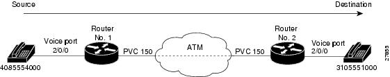
Establishing two-way communications using VoATM requires a specific voice connection between two defined endpoints. As shown in Figure 85, the plain old telephone service (POTS) dial peer establishes the source (the originating telephone number and voice port) of the call, and the VoATM dial peer establishes the destination by associating the destination phone number with a specific ATM virtual circuit.
Figure 85 Calls from the Perspective of Router 1
In Figure 85 the destination string, 14085554000, coming from the source, maps to U.S. phone number 555-4000, with the digit "1" plus the area code "408" preceding the number. When configuring the destination pattern, set the dial string to match the local dial conventions.
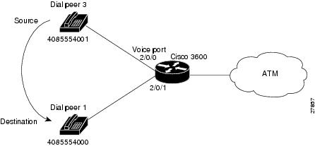
When both POTS dial peers are connected to the same router and share the same destination IP address, the VoATM dial peer does not need to be configured (see Figure 86).
Figure 86 Communication Between Dial Peers Sharing the Same Router
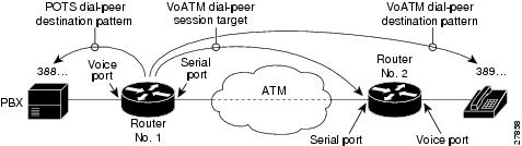
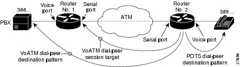
When configuring VoATM dial peers, an understanding of the relationship between the destination pattern and the session target is critical. The destination pattern represents the pattern for the device at the voice connection endpoint, such as a telephone or a PBX. The session target represents the serial port on the peer router at the other end of the ATM connection. Figure 87 and Figure 88 show the relationship between the destination pattern and the session target, as seen from the perspective of both routers in a VoATM configuration.
Figure 87 Relationship Between the Destination Pattern and Session Target from the Perspective of Router 1
Figure 88 Relationship Between the Destination Pattern and Session Target from the Perspective of Router 2
For more information regarding dial peers, see the "Configuring Dial Plans, Dial Peers, and Digit Manipulation" chapter.
VoATM Restrictions
The following are restrictions regarding V0ATM:
•
•
–
–
•
–
–
–
–
•
•
VoATM Prerequisite Tasks
Before configuring VoATM, perform the following tasks:
•
•
•
•
•
–
–
•
VoATM Configuration Task List
To configure VoATM, perform the following tasks:
•
•
•
•
•
Configuring ATM Interfaces for Voice Traffic Using AAL5
ATM interfaces must be configured for voice traffic using AAL5 and the VoATM configuration must be performed on both sides of the voice connection. The only commands in ATM virtual circuit configuration mode that are used for ATM voice PVCs are encapsulation aal5mux voice, vbr-rt, and ilmi. For more information on the encapsulation command, see the Cisco IOS Wide-Area Networking Command Reference.
To calculate the minimum peak, average, and burst values for the number of voice calls, perform the following calculations:
•
•
–
•
–
To configure ATM interfaces to support voice traffic, use the following commands beginning in global configuration mode:
Verifying the ATM PVC Configuration
Verify the ATM PVC configuration by using the show atm vc command. To verify connectivity, do not use the ping command over a voice PVC because the command applies to data only. Use the ping command over the data PVC to verify that the data and voice PVCs are set to the same destination.
Configuring AAL2 Encapsulation for VoATM
AAL2 encapsulation for VoATM must be configured and the VoATM configuration must be performed on the Cisco MC3810 multiservice concentrators at both ends of the ATM link. AAL2 is not supported on the Cisco 3600 series routers.
Note
To configure AAL2 encapsulation for VoATM, perform the following tasks:
•
•
Configuring T1/E1 Trunks
To configure the T1/E1 trunk, use the following commands beginning in global configuration mode:
Configuring Call Admission Control
Configuring the call admission control (CAC) is optional for the Cisco MC3810 multiservice concentrator because the MC3810 multiservice concentrator can be configured as master or slave. By default, a Cisco MC3810 multiservice concentrator is a CAC slave.
Typically the ATM trunk is configured with the CAC master at one end (performing CAC during fax/modem up speed) and slave at the opposite end. When the Cisco MC3810 multiservice concentrator is configured as a slave, it sends a request for CAC to the CAC master.
To configure a Cisco MC3810 multiservice concentrator as a CAC master, usethe following commands beginning in global configuration mode:
To return a Cisco MC3810 multiservice concentrator to its default operation as a CAC slave, use the following commands beginning in global configuration mode:
Configuring Subcell Multiplexing
This section describes the configuration tasks necessary to enable AAL2 common part sublayer (CPS) subcell multiplexing when the Cisco MC3810 multiservice concentrator interoperates with a voice interface service module (VISM) in an MGX switch. The commands and procedures in this section are specific to the Cisco MC3810 multiservice concentrator.
To configure the Cisco MC3810 multiservice concentrator to perform subcell multiplexing, use the following commands beginning in global configuration mode:
Configuring VoATM Dial Peers
Configuring dial peers to support VoATM should be performed in a back-to-back configuration before separating them across the ATM network. The back-to-back configuration enables the testing of a voice connection. If a voice connection cannot be made after both peers are placed in the network, then you have a network problem. For information about configuring POTS dial peers, see the "Configuring Dial Plans, Dial Peers, and Digit Manipulation" chapter.
To configure VoATM dial peers, use the following commands beginning in global configuration mode:
Configuring VoATM Dial Peers to Support AAL2
To configure the voice network dial peers to support AAL2 on a Cisco MC3810 multiservice concentrator, use the following commands beginning in global configuration mode:
Configuring VoATM Dial Peers for Cisco Trunk Calls
If Cisco trunk calls are transmitted over ATM, the dial peers must be configured to specifically support the calls. Cisco trunk calls are permanent calls.
Note
To configure a VoATM dial peer to support Cisco trunk calls, use the following commands beginning in global configuration mode:
Configuring Dial-Peer Hunting
To configure dial-peer hunting, use the following commands in global configuration mode:
To disable dial-peer hunting, use the following commands beginning in global configuration mode:
Configuring Cisco Trunk Permanent Calls
The Cisco trunk call functionality provides true permanent, private-line connections; comprehensive busyout support for trunk connection; and transparent CAS protocol transport to allow the trunk to carry arbitrary ABCD signaling protocols. Conversion from North American signaling protocols to CEPT (Conférence Européenne des Postes et des Télécommunications) signaling protocols used for European voice networks and remote analog to digital channel-bank operation for converting from DVM to AVM configurations is also provided.
To configure Cisco-trunk permanent calls, use the following commands beginning in global configuration mode:
Note
Verifying the Voice Connection
To verify that the voice connection is working, perform the following steps:
Step 1
Step 2
Step 3
Step 4
Step 5
Step 6
Troubleshooting Tips
To resolve suspected problems, perform the following tasks:
Step 1
Step 2
Step 3
Note
Verifying the ATM Interface Configuration
To verify the ATM interface configuration, perform the following tasks:
•
Router# show atm vcVCD / Peak Avg/Min BurstInterface Name VPI VCI Type Encaps SC Kbps Kbps Cells Sts0 1 0 5 PVC SAAL UBR 0 UP0 2 0 16 PVC ILMI UBR 0 UP0 379 0 60 SVC SNAP UBR 0 UP0 986 0 84 SVC SNAP UBR 0 UP0 14 0 133 SVC VOICE VBR 64 16 10 UP0 15 0 134 SVC VOICE VBR 64 16 10 UP0 16 0 135 SVC VOICE VBR 64 16 10 UP0 17 0 136 SVC VOICE VBR 64 16 10 UP0 18 0 137 SVC VOICE VBR 64 16 10 UP0 19 0 138 SVC VOICE VBR 64 16 10 UP0 20 0 139 SVC VOICE VBR 64 16 10 UP0 21 0 140 SVC VOICE VBR 64 16 10 UP0 22 0 141 SVC VOICE VBR 64 16 10 UP0 23 0 142 SVC VOICE VBR 64 16 10 UP0 24 0 143 SVC VOICE VBR 64 16 10 UP0 25 0 144 SVC VOICE VBR 64 16 10 UP0 26 0 145 SVC VOICE VBR 64 16 10 UP0 27 0 146 SVC VOICE VBR 64 16 10 UP0 28 0 147 SVC VOICE VBR 64 16 10 UP
Note
•
Router# show atm pvc 0/5ATM0: VCD: 2, VPI: 0, VCI: 5, Connection Name: SAALUBR, PeakRate: 56AAL5-SAAL, etype:0x4, Flags: 0x26, VCmode: 0x0OAM frequency: 0 second(s), OAM retry frequency: 1 second(s), OAM retry frequency: 1 second(s)OAM up retry count: 3, OAM down retry count: 5OAM Loopback status: OAM DisabledOAM VC state: Not ManagedILMI VC state: Not ManagedInARP DISABLEDInPkts: 2044, OutPkts: 2064, InBytes: 20412, OutBytes: 20580InPRoc: 2044, OutPRoc: 2064, Broadcasts: 0InFast: 0, OutFast: 0, InAS: 0, OutAS: 0OAM cells received: 0F5 InEndloop: 0, F5 InSegloop: 0, F5 InAIS: 0, F5 InRDI: 0F4 InEndloop: 0, F4 InSegloop: 0, F4 InAIS: 0, F4 InRDI: 0OAM cells sent: 0F5 OutEndloop: 0, F5 OutSegloop: 0, F5 OutRDI: 0F4 OutEndloop: 0, F4 OutSegloop: 0, F4 OutRDI: 0OAM cell drops: 0Compress: DisabledStatus: INACTIVE, State: NOT_IN_SERVICE!Router# show atm pvc 0/16ATM0: VCD: 1, VPI: 0, VCI: 16, Connection Name: ILMIUBR, PeakRate: 56AAL5-ILMI, etype:0x0, Flags: 0x27, VCmode: 0x0OAM frequency: 0 second(s), OAM retry frequency: 1 second(s), OAM retry frequency: 1 second(s)OAM up retry count: 3, OAM down retry count: 5OAM Loopback status: OAM DisabledOAM VC state: Not ManagedILMI VC state: Not ManagedInARP DISABLEDInPkts: 398, OutPkts: 421, InBytes: 30493, OutBytes: 27227InPRoc: 398, OutPRoc: 421, Broadcasts: 0InFast: 0, OutFast: 0, InAS: 0, OutAS: 0OAM cells received: 0F5 InEndloop: 0, F5 InSegloop: 0, F5 InAIS: 0, F5 InRDI: 0F4 InEndloop: 0, F4 InSegloop: 0, F4 InAIS: 0, F4 InRDI: 0OAM cells sent: 0F5 OutEndloop: 0, F5 OutSegloop: 0, F5 OutRDI: 0F4 OutEndloop: 0, F4 OutSegloop: 0, F4 OutRDI: 0OAM cell drops: 0Compress: DisabledStatus: INACTIVE, State: NOT_IN_SERVICE•
Router# show interface atm 0ATM0 is up, line protocol is upHardware is PQUICC Atom1Internet address is 9.1.1.6/8MTU 1500 bytes, sub MTU 1500, BW 1536 Kbit, DLY 20000 usec,reliability 255/255, txload 22/255, rxload 11/255NSAP address: 47.0091810000000002F26D4901.000011116666.06Encapsulation ATM292553397 packets input, -386762809 bytes164906758 packets output, 1937663833 bytes0 OAM cells input, 0 OAM cells output, loopback not setKeepalive not supportedEncapsulation(s):, PVC mode1024 maximum active VCs, 28 current VCCsVC idle disconnect time: 300 secondsSignalling vc = 1, vpi = 0, vci = 5UNI Version = 4.0, Link Side = userLast input 00:00:00, output 2d05h, output hang neverLast clearing of "show interface" counters neverInput queue: -1902/75/0 (size/max/drops); Total output drops: 205Queueing strategy: weighted fairOutput queue: 0/1000/64/0 (size/max total/threshold/drops)Conversations 0/0/256 (active/max active/max total)Reserved Conversations 0/0 (allocated/max allocated)5 minute input rate 67000 bits/sec, 273 packets/sec5 minute output rate 136000 bits/sec, 548 packets/sec76766014 packets input, 936995443 bytes, 0 no bufferReceived 0 broadcasts, 0 runts, 0 giants, 0 throttles0 input errors, 0 CRC, 0 frame, 0 overrun, 0 ignored, 0 abort367264676 packets output, 3261882795 bytes, 0 underruns0 output errors, 0 collisions, 2 interface resets0 output buffer failures, 0 output buffers swapped out•
Router# show atm video-voice addressnsap address type ilmi status47.0091810000000002F26D4901.00107B4832E1.FE VOICE_AAL5 Confirmed47.0091810000000002F26D4901.00107B4832E1.C8 VIDEO_AAL1 ConfirmedVerifying the VoATM Connection
Verify that the voice connection is working by performing the following steps:
Step 1
Step 2
Step 3
•
•
•
•
Troubleshooting Tips
If a call does not connect, resolve the problem by performing the following tasks:
•
•
•
VoATM Configuration Examples
Configuration examples for VoATM are shown in the following sections:
•
•
•
•
Back-to-Back VoATM PVCs Example
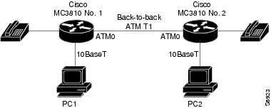
Figure 89 shows a configuration example for two Cisco MC3810 multiservice concentrators configured back-to-back, with VoATM configured for both concentrators. This setup is a useful for testing the VoATM configuration locally to ensure that voice connections can be made before configuring VoATM across a larger network. Following the figure are the commands required for configuring the Cisco MC3810 multiservice concentrators in this example.
Figure 89 Back-to-Back VoATM PVCs Configuration
Voice and Data Traffic over ATM PVCs Example
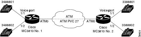
Figure 90 shows an example for both voice and data traffic over ATM between two Cisco MC3810 multiservice concentrators, including configuration for voice ports and dial peers. Following the figure are the commands required for configuring the Cisco MC3810 multiservice concentrators in this example.
Figure 90 Voice and Data Traffic over ATM PVCs Configuration
VoATM for Cisco 3600 Series Routers Configuration Example
The following is a sample configuration for VoATM on a Cisco 3600 series router:
version 12.2!hostname c3640_1!no ip subnet-zerono ip routingip wccp version 2!dial-control-mib max-size 500!process-max-time 200!interface Ethernet0/0ip address 172.28.129.54 255.255.255.192ip helper-address 171.71.20.62no ip directed-broadcastno ip route-cacheno ip mroute-cache!interface Serial0/0no ip addressno ip directed-broadcastno ip route-cacheno ip mroute-cacheno fair-queue!interface Ethernet0/1no ip addressno ip directed-broadcastno ip route-cacheno ip mroute-cacheshutdown!interface ATM1/0no ip addressno ip directed-broadcastno ip route-cacheno ip mroute-cacheno atm ilmi-keepalivepvc 1/100vbr-rt 1000 500encapsulation aal5mux voice!no scrambling-payloadimpedance 120-ohmno fair-queue!interface ATM1/1no ip addressno ip directed-broadcastno ip route-cacheno ip mroute-cacheno atm ilmi-keepalivepvc 2/100vbr-rt 1000 500encapsulation aal5mux voice!no scrambling-payloadimpedance 120-ohmno fair-queue!interface ATM1/1.1 point-to-pointno ip directed-broadcastno ip route-cacheno ip mroute-cachepvc 3/200vbr-rt 64 64 4encapsulation aal5mux voice!interface ATM1/2no ip addressno ip directed-broadcastno ip route-cacheno ip mroute-cacheshutdownno atm ilmi-keepaliveno scrambling-payloadimpedance 120-ohmno fair-queue!interface ATM1/3no ip addressno ip directed-broadcastno ip route-cacheno ip mroute-cacheshutdownno atm ilmi-keepaliveno scrambling-payloadimpedance 120-ohmno fair-queue!interface ATM1/4no ip addressno ip directed-broadcastno ip route-cacheno ip mroute-cacheshutdownno atm ilmi-keepaliveno scrambling-payloadimpedance 120-ohmno fair-queue!interface ATM1/5no ip addressno ip directed-broadcastno ip route-cacheno ip mroute-cacheshutdownno atm ilmi-keepaliveno scrambling-payloadimpedance 120-ohmno fair-queue!interface ATM1/6no ip addressno ip directed-broadcastno ip route-cacheno ip mroute-cacheshutdownno atm ilmi-keepaliveno scrambling-payloadimpedance 120-ohmno fair-queue!interface ATM1/7no ip addressno ip directed-broadcastno ip route-cacheno ip mroute-cacheshutdownno atm ilmi-keepaliveno scrambling-payloadimpedance 120-ohmno fair-queue!interface ATM3/0no ip addressno ip directed-broadcastno ip route-cacheno ip mroute-cachemap-group atm1atm clock INTERNALpvc 2/200encapsulation aal5snapno atm auto-configurationno atm ilmi-keepaliveno atm address-registrationno atm ilmi-enablepvc voice 1/100vbr-rt 5000 2500encapsulation aal5mux voice!ip default-gateway 172.28.129.1ip classlessip route 171.70.20.62 255.255.255.255 172.28.129.1no ip http server!map-list atm1ip 4.4.4.2 atm-vc 2 broadcast!map-class frame-relay fr1!map-class frame-relay voiceno frame-relay adaptive-shapingframe-relay cir 128000frame-relay bc 128000snmp-server engineID local 00000009020000107BC778C0snmp-server community public ROsnmp-server community SNMPv2c view v2default ROsnmp-server community v2 view v1default ROsnmp-server community config view v1default ROsnmp-server community voice view v1default ROsnmp-server packetsize 4096snmp-server enable traps snmpsnmp-server enable traps casasnmp-server enable traps configsnmp-server enable traps voice poor-qovsnmp-server host 171.71.128.229 version 2c SNMPv2c config voice snmpsnmp-server host 171.71.128.242 version 2c public config voice snmpsnmp-server host 171.71.129.16 version 2c public tty frame-relay isdn hsrpconfig entity envmon bgp rsvp rtr syslog stun sdllc dspu rsrb dlsw sdlc snmpsnmp-server host 171.71.129.164 version 2c public config voice snmp!line con 0exec-timeout 0 0transport input noneline aux 0line vty 0 4session-timeout 10password applelogin!voice-port 2/0/0input gain 5output attenuation 5!voice-port 2/0/1input gain 5output attenuation 5!voice-port 2/1/0input gain 5output attenuation 5!voice-port 2/1/1input gain 5output attenuation 5!dial-peer voice 2 potsdestination-pattern 4001!dial-peer voice 8000 potsdestination-pattern 84000!dial-peer voice 9000 potsdestination-pattern 94000!dial-peer voice 9001 potsdestination-pattern 94001!dial-peer voice 348 voatmdestination-pattern 348....signal-type ext-signalsession target ATM3/0 pvc 1/100!dial-peer voice 338 voatmdestination-pattern 338....signal-type ext-signalsession target ATM1/0 pvc 1/100!dial-peer voice 2222 voatmpreference 1session target ATM1/0 pvc 1/100!dial-peer voice 9500 voatmdestination-pattern 95...session target ATM3/0 pvc 1/100!dial-peer voice 8400 potsdestination-pattern 84000!dial-peer voice 50000 voatmdestination-pattern 5264000session target ATM3/0 pvc 1/100!dial-peer voice 10000 potsdestination-pattern 5254000port 2/0/0!dial-peer voice 10001 potsdestination-pattern 4000789port 2/1/0!num-exp 1 1234num-exp 2 2234num-exp 12 34567890num-exp 55 66666endVoATM for the Cisco MC3810 Multiservice Concentrator Configuration Example
The following is a sample configuration for VoATM on Cisco MC3810 multiservice concentrators at opposite ends of an AAL2 trunk:
End A
version 12.2service timestamps debug uptimeservice timestamps log uptimeno service password-encryption!hostname aal2-faxtest1!network-clock base-rate 64kip subnet-zero!isdn voice-call-failure 0!voice-card 0!controller T1 0mode atmframing esflinecode b8zs!controller T1 1mode casframing esflinecode b8zsinterface Ethernet0ip address 1.7.78.1 255.255.0.0!interface Serial0no ip address!interface Serial1no ip addressshutdowninterface ATM0no ip addressip mroute-cacheno atm ilmi-keepalivepvc 99/99vbr-rt 1536 1536 1000encapsulation aal2!voice-port 1:1no echo-cancel enabletimeouts wait-release 3connection trunk 1001!dial-peer voice 1001 voatmdestination-pattern 1001called-number 2001session protocol aal2-trunksession target ATM0 pvc 99/99 21dtmf-relaysignal-type transparentcodec aal2-profile custom 100 g711ulawno vad!dial-peer voice 201 potsdestination-pattern 2001port 1:1endEnd B
Current configuration:!version 12.2service timestamps debug uptimeservice timestamps log uptimeno service password-encryption!hostname aal2-faxtest2!network-clock base-rate 64kip subnet-zero!isdn voice-call-failure 0!voice-card 0!controller T1 0mode atmframing esfclock source internallinecode b8zs!controller T1 1mode casframing esflinecode b8zsds0-group 1 timeslots 1 type e&m-immediate-start!interface Ethernet0ip address 1.7.78.4 255.255.0.0!interface Serial0shutdown!interface Serial1no ip addressshutdown!interface ATM0ip address 223.223.226.3 255.255.255.0ip mroute-cacheno atm ilmi-keepalivepvc 99/99vbr-rt 1536 1536 1000encapsulation aal2!voice-port 1:1timeouts wait-release 3connection trunk 2001!dial-peer voice 201 potsdestination-pattern 1001port 1:1!dial-peer voice 1001 voatmdestination-pattern 2001called-number 1001session protocol aal2-trunksession target ATM0 pvc 99/99 21dtmf-relaysignal-type transparentcodec aal2-profile custom 100 g711ulawno vadline con 0exec-timeout 0 0transport input noneline aux 0line 2 3line vty 0 4login!end