Feedback
Table Of Contents
CIVS-SENC-4P Front and Back View
CIVS-SENC-8P Front and Back View
Pin Definitions of the General I/O Terminal Blocks
Setting up the Encoder on the Network
Setting up the Encoder Behind a Router
Setting up the Encoder Using a Static IP Address
Overview
The Cisco video surveillance encoders, models CIVS-SENC-4P and CIVS-SENC-8P, convert analog video into high quality digital video, and set a new standard in encoder security. The CIVS-SENC-4P and CIVS-SENC-8P models contain the following key features:
•
Allow 4-CH or 8-CH high resolution video capture with a high frame rate.
•
•
•
•
•
•
These features make the CIVS-SENC-4P and CIVS-SENC-8P models easy to install and integrate with an existing analog camera. As a highly innovative video encoder series, the CIVS-SENC-4P and CIVS-SENC-8P models allow you to easily upgrade to a full-featured, high-end, IP surveillance solution.
Read Before Use
It is important to verify that all contents received are complete according to the package contents list (see the "Package Contents" section). Take note of the warnings in the Quick Start Guide before installing the encoder; then carefully read and follow the instructions in the Network Deployment section of this guide (see the "Network Deployment" section) to avoid damage during installation.
The encoder is a network device, and it is designed for various applications, including video sharing, general security/surveillance, and so on. The Configuration chapter (see the "Configuration" section) suggests ways to make best use of the encoder, and to ensure proper operation.
Package Contents
The Cisco video surveillance encoder package includes these items:
•
•
•
•
Physical Description
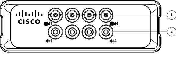
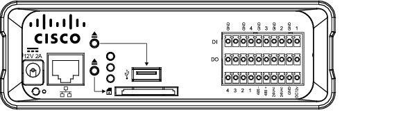
CIVS-SENC-4P Front and Back View
Figure 1-1 shows the front view of the CIVS-SENC-4P encoder. The top row is comprised of four video input slots, and the bottom row is comprised of four audio input slots.
Figure 1-1 CIVS-SENC-4P Front View
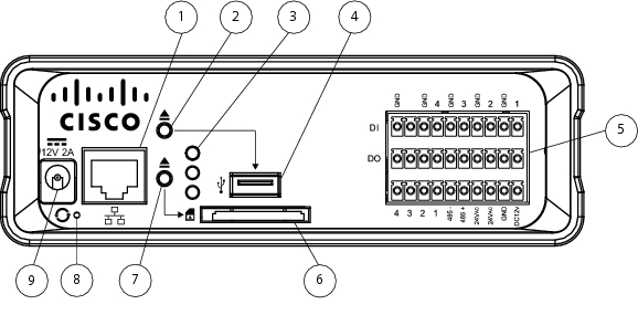
Figure 1-2 shows the back view of the CIVS-SENC-4P encoder.
Figure 1-2 CIVS-SENC-4P Back View
Ethernet 10/100/1000 RJ45 port
SD/SDHC card slot. While the SD/SDHC slot is on the device, it is not currently supported by Cisco.
In encoders that support USB, press this button before removing the USB device.
In encoders that support SD/SDHC, press this button before removing the SD/SDHC device.
Status LEDs. For more information, see the "Status LED" section.
Reset button (recessed). For more information, see the "Hardware Reset" section.
USB port. While the USB port is on the device, it is not currently supported by Cisco.
Power input
General I/O terminal block. For more information, see the "General I/O Terminal Block" section.
Note
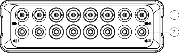
CIVS-SENC-8P Front and Back View
Figure 1-3 shows the front view of the CIVS-SENC-8P encoder. The top row is comprised of eight video input slots, and the bottom row is comprised of eight audio input slots.
Figure 1-3 CIVS-SENC-8P Front View
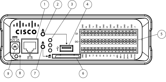
Figure 1-4 shows the back view of the CIVS-SENC-8P encoder.
Figure 1-4 CIVS-SENC-8P Back View
Ethernet 10/100/1000 RJ45 port
SD/SDHC card slot. While the SD/SDHC slot is on the device, it is not currently supported by Cisco.
In encoders that support USB, press this button before removing the USB device.
In encoders that support SD/SDHC, press this button before removing the SD/SDHC device.
Status LEDs. For more information, see the "Status LED" section.
Reset button (recessed). For more information, see "Hardware Reset" section.
USB port. While the USB port is on the device, it is not currently supported by Cisco.
Power input
General I/O terminal block. For more information, see "General I/O Terminal Block" section.
Note
General I/O Terminal Block
This encoder provides a general I/O terminal block which is used to connect external input /output devices. For information about the pin definitions, see the "Pin Definitions of the General I/O Terminal Blocks" section.
Pin Definitions of the General I/O Terminal Blocks
Figure 1-5 shows the pin locations on the back panel of the CIVS-SENC-4P encoder, and Table 1-1 provides definitions for each of the pins.l
Figure 1-5 CIVS-SENC-4P Pin Locations
Figure 1-6 shows the pin locations on the back panel of the CIVS-SENC-8P encoder, and Table 1-2 provides definitions for each of the pins.
Figure 1-6 CIVS-SENC-8P Pin Locations
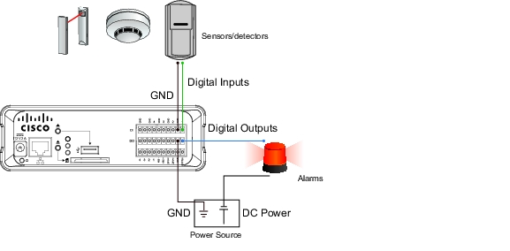
DI/DO Diagram
Figure 1-7 shows the connections necessary to set up the encoder with various external devices.
Figure 1-7 DI/DO Connections
Note
•
•
•
Status LED
The LED indicates the status of the encoder. Table 1-3 describes the different status levels of the Yellow (SD), Green (Network), and Red (Power) LEDs.
Table 1-4 describes LED blinking states.
Hardware Reset
See Figure 1-2 (CIVS-SENC-4P) or Figure 1-4 (CIVS-SENC-8P) for the location of the hardware reset button on your encoder. The reset button is used to reset the system or to restore the factory default settings. Sometimes, if your encoder is experiencing a problem, resetting the system can return the encoder to normal operation. If, after performing a reset, the problem remains, restore the factory settings and install the system again.
Use one of the following methods to reset or restore the settings:
•
•
Network Deployment
Setting up the Encoder on the Network
To connect the encoder to the camera and the network, follow these steps:
Procedure
Step 1
Step 2
Figure 1-8 Video and Audio Connections
Step 3
Step 4
Step 5
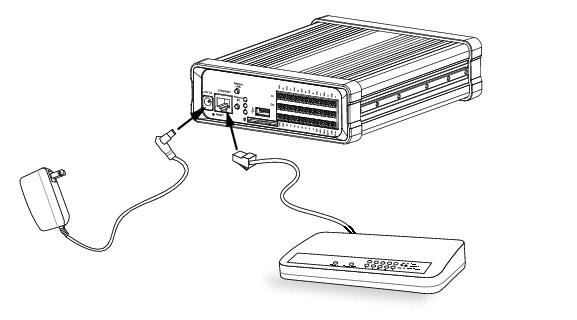
Figure 1-9 Network, Power, and External Device Connections
Step 6
•
•
•
Setting up the Encoder Behind a Router
To set up the encoder behind a router, perform the following procedure:
Before you begin
•
•
Procedure
Step 1
Step 2
•
•
•
•
•
•
If you have changed the port numbers on the Network window, open the ports accordingly on your router. For information on how to forward ports on the router, refer to the user manual for your router.
Step 3
Setting up the Encoder Using a Static IP Address
Choose this connection type if you are required to use a static IP address for the encoder. For more information, see the "LAN Settings" section.
Enabling Authentication
Cisco recommends that you use the following procedure to enable authentication on the encoder via its Web-based user interface.
Procedure
Step 1
For more information about accessing the encoder user interface, see the "Accessing the Encoder" section.
Step 2
Note
Step 3
Step 4
Step 5
HTTPS is not supported by VSM.
Step 6
•
•
•
Note
Ready to Use
When you have completed setup, you are ready to access the encoder. For more information, see the "Accessing the Encoder" section.