Feedback
Table Of Contents
Accessing Configuration Options
Modifying or Deleting a User Account
Create and Install Certificate Methods
Creating a Self-signed Certificate Automatically
Creating a Self-signed Certificate Manually
Creating a Certificate Request and Install
Manually Setup the IP Address Settings
QoS (Quality of Service) Settings
Using an RTSP Player to Access the Encoder
Current Streaming Connection Information
Audio and Video Settings Overview
Video Quality Settings for Stream 1
Camera Tampering Detection Window
Configuring Camera Preset Positions
Configuring Camera Patrol Settings
Create Your own Customizations
Managing Event Settings on the Application Window
Exporting the Daylight Savings Time File Configuration
Exporting the Setting Backup File
Uploading Daylight Saving Time Rules
Uploading the Custom Language File
Uploading the Setting Backup File
Configuration
This chapter describes the configuration options of the Cisco video surveillance encoders, models CIVS-SENC-4P and CIVS-SENC-8P, and includes the following sections:
•
Accessing Configuration Options
•
Accessing Configuration Options
You must have administrator rights to access the encoder configuration options. You can choose to display configuration options in one of two modes—Basic Mode or Advanced Mode. Advanced Mode displays all possible configuration options for the CIVS-SENC-4P and CIVS-SENC-8P encoder models, and Basic Mode displays a subset of all options.
To access configuration options, perform the following procedure:
Procedure
Step 1
Step 2
Step 3
System Window
This section describes the configuration options available on the System window, and contains the following topics:
For information about accessing the System window, see the "Accessing Configuration Options" section.
When you have finished with the settings on this window, click Save to enable the settings.
System Settings
Table 5-1 describes the System settings.
System Time Settings
Table 5-2 describes the System Time settings.
Table 5-2 System Time Settings
Time zone
This setting is available in Advanced Mode only. Choose the appropriate time zone from the drop-down list. For information about uploading Daylight Savings Time rules on the Maintenance window, see the "Uploading Daylight Saving Time Rules" section.
Keep current date and time
Choose this option to preserve the current date and time of the encoder. The internal real-time clock of the encoder maintains the date and time even when the system power is turned off.
Synchronize with computer time
Choose this option to synchronize the date and time of the encoder with the local computer. The read-only date and time of the local computer is displayed as updated.
Manual
The administrator can enter the date and time manually. Note that the date and time formats are [yyyy/mm/dd] and [hh:mm:ss].
Automatic
The Network Time Protocol synchronizes computer clocks automatically by periodically querying an NTP Server.
•
•
Security Window
This section describes the settings on the Security window, such as how to enable password protection and create multiple accounts. It includes the following topics:
For information about accessing the Security window, see the "Accessing Configuration Options" section.
When you have finished with the settings on this window, click Save to enable the settings.
Root Password Settings
Table 5-3 describes the Root Password settings.
Manage Privilege Settings
This setting is available in Advanced Mode only.
Table 5-4 describes the Manage Privilege settings.
Table 5-4 Manage Privilege Settings
Digital output
Choose to grant users operator or viewer privileges over digital output.
PTZ control
Choose to grant users operator or viewer privileges over camera PTZ controls. For more information about PTZ controls, see the "Camera Control Area" section.
Allow anonymous viewing
If you choose this item, any client can access the live stream without entering a User ID and Password.
Manage User Settings
Administrators can add up to 20 user accounts. Access rights are sorted by user privilege—Administrator, Operator, and Viewer. Only administrators can access the Configuration window. Viewers can access only the home window for live viewing.
You can perform the following tasks to manage users:
•
Adding a User
To add a user, perform the following procedure:
Procedure
Step 1
Step 2
Step 3
Step 4
Step 5
Modifying or Deleting a User Account
To modify or delete a user account:
Procedure
Step 1
Step 2
•
•
HTTPS Window
This feature is available in Advanced Mode only.
This section describes how to enable authentication and encrypted communication over SSL (Secure Socket Layer). This helps protect streaming data transmission over the Internet by using a higher security level. This section contains the following topics:
•
When you have finished with the settings on this window, click Save to enable the settings.
Enable HTTPS Settings
To enable HTTPS communication, perform the following procedure:
Before you begin
Create and install a certificate. For more information, see "Create and Install Certificate Methods" section.
Procedure
Step 1
Step 2
Step 3
Step 4
Step 5
Create and Install Certificate Methods
Before using HTTPS for communication with the encoder, a certificate must be created. There are three options for creating and installing a certificate:
•
•
•
For information about removing certificates, see "Remove a Signed Certificate" section.
Creating a Self-signed Certificate Automatically
To create a self-signed certificate automatically, perform the following procedure:
Procedure
Step 1
Step 2
Step 3
Step 4
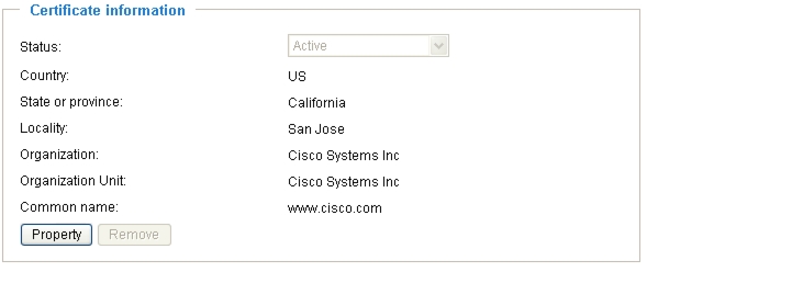
The certificate Information is displayed automatically at the bottom of the window.
Step 5
Figure 5-1 Certificate Information
Step 6
Step 7
Security Alert dialog boxes may pop up.
Step 8
Creating a Self-signed Certificate Manually
To create a self-signed certificate manually, perform the following procedure:
Procedure
Step 1
Step 2
Step 3
Step 4
The Certificate Information is displayed automatically at the bottom of the window.
Step 5
Figure 5-2 Certificate Information
Creating a Certificate Request and Install
Select this option if you want to create a certificate from a certificate authority.
To create a certificate request and install, perform the following procedure:
Procedure
Step 1
Step 2
Step 3
Step 4
Step 5
Step 6
Step 7
Cancel HTTPS Settings
To cancel HTTPS Settings, perform the following procedure:
Procedure
Step 1
Step 2
Step 3
A warning dialog box displays.
Step 4
The web page redirects to a non-HTTPS page automatically.
Remove a Signed Certificate
If you want to create and install other certificates, you must first remove the existing one.
To remove a signed certificate, perform the following procedure:
Procedure
Step 1
Step 2
Step 3
Step 4
Step 5
SNMP Window
While SNMP is shown on the user interface, it is not currently supported by Cisco.
Network Window
This section describes the options for configuring a wired network connection for the encoder on the Network window, and it contains the following topics:
For information about accessing the Network window, see the "Accessing Configuration Options" section.
When you have finished with the settings on this window, click Save in the relevant section to enable the settings.
Network Type Settings
Table 5-5 describes the top-level options in the Network Type area:
Table 5-5 Network Type Settings
LAN
Choose this option when the encoder is deployed on a local area network (LAN) and is intended to be accessed by local computers. The default setting for the Network Type is LAN. For more information about LAN settings, see the "LAN Settings" section.
PPPoE
While PPPoE is shown on the user interface, it is not currently supported by Cisco.
Enable IPv6
While Enable IPv6 is shown on the user interface, it is not currently supported by Cisco.
LAN Settings
Table 5-6 describes the LAN settings.
Table 5-6 LAN Settings
Get IP address automatically
Choose this option to obtain an available dynamic IP address assigned by the DHCP server each time the encoder is connected to the LAN.
Use fixed IP address
Select this option to manually assign a static IP address to the video server. For more information about the Use fixed IP address settings, see the "Use Fixed IP Address Settings" section.
Enable UPnP presentation
While Enable UPnP presentation is shown on the user interface, it is not currently supported by Cisco.
Enable UPnP port forwarding
While Enable UPnP port forwarding is shown on the user interface, it is not currently supported by Cisco.
Note
Use Fixed IP Address Settings
Table 5-7 describes the Use fixed IP address settings.
Manually Setup the IP Address Settings
Choose this option to manually set up IPv6 settings if your network environment does not have DHCPv6 server and router advertisements-enabled routers. Table 5-8 describes the information required when you choose this setting.
IEEE 802.1x Settings
While IEE 802.1x is shown on the user interface, it is not currently supported by Cisco.
QoS (Quality of Service) Settings
This feature is available in Advanced Mode only.
Quality of Service refers to a resource reservation control mechanism, which guarantees a certain quality to different services on the network. Quality of service guarantees are important if the network capacity is insufficient, especially for real-time streaming multimedia applications. Quality can be defined as, for example, a maintained level of bit rate, low latency, no packet dropping, and so on.
The following are the main benefits of a QoS-aware network:
•
•
To use QoS in a network environment, all network switches and routers in the network must include support for QoS. Also, the network video devices used in the network must be QoS-enabled.
The following two QoS models are available:
•
CoS (The VLAN 802.1p Model)
IEEE802.1p defines a QoS model at OSI Layer 2 (Data Link Layer), which is called CoS (Class of Service). It adds a 3-bit value to the VLAN MAC header, which indicates prioritization from 0~7 (eight different classes of service are available). The priority is set up on the network switches, which then use different queuing disciplines to forward the packets.
Table 5-9 describes the settings that are required when you choose CoS.
If you assign Video the highest level, the switch will handle video packets first.
Note
•
•
•
QoS/DSCP (The DiffServ Model)
DSCP-ECN defines QoS at Layer 3 (Network Layer). The Differentiated Services (DiffServ) model is based on packet marking and router queuing disciplines. The marking is done by adding a field to the IP header, called the DSCP (Differentiated Services Codepoint). This is a 6-bit field that provides 64 different class IDs. It gives an indication of how a given packet is to be forwarded, known as the Per Hop Behavior (PHB). The PHB describes a particular service level in terms of bandwidth, queueing theory, and dropping (discarding the packet) decisions. Routers at each network node classify packets according to their DSCP value and give them a particular forwarding treatment; for example, how much bandwidth to reserve for it.
Table 5-10 describes the settings that are required when you choose QoS/DSCP.
HTTP Settings
This feature is available in Advanced Mode only.
To use HTTP authentication, make sure you have set a password for the encoder. For more information, see the "Security Window" section.
Table 5-11 describes the HTTP settings.
HTTPS Settings
By default, the HTTPS port is set to 443. It can also be assigned to another port number between 1025 and 65535.
Two Way Audio Settings
By default, the two way audio port is set to 5060. It can also be assigned to another port number between 1025 and 65535.
The encoder supports two way audio communication so that operators can transmit and receive audio simultaneously. By using the built-in or external microphone and an external speaker, you can communicate with people around the encoder.
Note
Table 5-12 describes the Two Way Audio control buttons that are available on the encoder home window.
FTP Settings
The FTP server allows the user to save recorded video clips. By default, the FTP port is set to 21. It can also be assigned to another port number between 1025 and 65535.
RTSP Streaming Settings
To use RTSP streaming authentication, make sure that you have set a password for the encoder. For more information about setting a password, see the "Security Window" section.
Table 5-13 describes the RTSP Streaming settings.
Table 5-13 RTSP Streaming Settings
Authentication
Depending on your network security requirements, the encoder provides three types of security settings for streaming via RTSP protocol: disable, basic, and digest.
•
•
•
Note
Table 5-14 describes the availability of RTSP streaming for the three authentication modes.
Access name for channel 1 ~ 4/8
The CIVS-SENC-4P encoder model supports four channels for live video viewing and the CIVS-SENC-8P model supports eight channels. Each channel allows you to view only one stream. The access name is used to differentiate the streaming source.
RTSP port
RTSP (Real-Time Streaming Protocol) controls the delivery of streaming media. By default, the port number is set to 554. This port can be changed to a value between 1025 and 65535.
RTP port for video
RTP (Real-time Transport Protocol) is used to deliver video and audio data to clients. By default, the RTP port for video is set to 5556.
This port can be changed to a value between 1025 and 65535, but the RTP port must be an even number.
RTCP port for video
RTCP (Real-time Transport Control Protocol) allows the encoder to transmit data by monitoring the Internet traffic volume. By default, the RTCP port for video is set to 5557.
The RTCP port is the RTP port number plus one, so it is always an odd number. When the RTP port changes, the RTCP port changes accordingly.
RTP port for audio
RTP (Real-time Transport Protocol) is used to deliver video and audio data to clients. By default, the RTP port for audio is set to 5558.
This port can be changed to a value between 1025 and 65535, but the RTP port must be an even number.
RTCP port for audio
RTCP (Real-time Transport Control Protocol) allows the encoder to transmit data by monitoring the Internet traffic volume. By default, the RTCP port for audio is set to 5559.
The RTCP port is the RTP port number plus one, so it is always an odd number. When the RTP port changes, the RTCP port changes accordingly.
Multicast settings for channel 1 ~ 4/8
Click the top-level items to display detailed configuration information.
Unicast video transmission delivers a stream through point-to-point transmission. Multicast, on the other hand, sends a stream to the multicast group address and allows multiple clients to acquire the stream at the same time by requesting a copy from the multicast group address. Enabling multicast, therefore, can effectively save Internet bandwith.
Table 5-15 describes the Multicast setting fields.
Table 5-14 Availability of RTSP Streaming
Disable
O
O
Basic
O
O
Digest
O
X
Using an RTSP Player to Access the Encoder
If you want to use an RTSP player to access the encoder, you must set the video mode to MPEG-4 and use the following RTSP URL command to request transmission of the streaming data:
rtsp://ip-address:rtsp-port/access-name-for-stream1~channel-1~4/8
The following example procedure shows how to request transmission of streaming data when the access name for stream 1 is set to "live.sdp":
Procedure
Step 1
Step 2
A URL dialog box is displayed.
Step 3
rtsp://ip-address:rtsp-port/access-name-for-stream1~channel-1~4/8
For example: rtsp://192.168.5.151:554/live.sdp
Step 4
The live video is displayed in your player.
Access List Settings
This feature is available in Advanced Mode only.
This describes configuration options available on the Access list window, including how to control access permission by verifying the client PC IP address. It contains the following topics:
For information about accessing the Access list window, see the "Accessing Configuration Options" section.
When you have finished with the settings on this window, click Save to enable the settings.
General Access List Settings
Table 5-16 describes the General access list settings.
Table 5-16 General Settings
Maximum number of concurrent streaming connection(s) limited to
Allows simultaneous live viewing for 1~10 clients (including stream 1 and stream 2). The default value is 10. If you modify the value and click Save, all current connections are disconnected and automatically attempt to re-link (IE Explore or Quick Time Player).
View Information
Click this button to display the connection status window showing a list of the current connections. For more information about current streaming connection information information, see the "Current Streaming Connection Information" section.
Enable access list filtering
Check this item and click Save to enable the access list filtering function.
Current Streaming Connection Information
Table 5-17 describes the features of the Connection Status window.
Table 5-17 Connection Status Information
IP address
Current connections to the encoder.
Elapsed time
The amount of time for which the client has been at the webpage
User ID
If the administrator has set a password for the webpage, clients must enter a user name and password to access the live video. The Client user name is displayed in the User ID column. If the administrator allows clients to link to the webpage without a user name and password, the User ID column remains empty.
Clients are allowed access to the live video without a user name and password in the following situations:
•
•
•
Refresh
Click this button to refresh all current connections.
Add to deny list
You can select entries from the Connection Status list and add them to the Deny List to deny access. Note that these connections are only disconnected temporarily and will try to re-link again automatically (in IE Explore or Quick Time Player). If you want to enable the denied list, check the Enable access list filtering checkbox (see Table 5-16) and then click Save in the General settings area.
Disconnect
To break off a current connection, select the connection, and then click Disconnect. Note that these connections are only disconnected temporarily and will try to re-link again automatically (in IE Explore or Quick Time Player).
Filter Type Settings
Select Allow or Deny as the filter type. If you choose the Allow filter type, only those clients whose IP addresses are on the Access List can access the Network Camera. If you choose the Deny filter type, those clients whose IP addresses are on the Access List are not allowed to access the Network Camera, while other clients can access it.
Filter
Once you have selected a filter type, you can then add a rule to the Access list. To add a filter rule to the Allowed/Denied list, perform the following procedure:
Procedure
Step 1
Step 2
Step 3
•
•
•
Step 4
Administrator IP Address
Choose the Always allow the IP address to access this device checkbox and enter the IP address that is to be given access.
Digital I/O Window
This section describes how to change digital input and digital output settings, and it contains the following topics:
For information about accessing the Digital I/O window, see the "Accessing Configuration Options" section.
When you have finished with the settings on this window, click Save to enable the settings.
Digital Input Settings
You can select High or Low to define normal status for the digital input. The encoder displays the current status.
Digital Output Settings
You can select Grounded or Open to define normal status for the digital output. The encoder displays whether or not the trigger is activated.
Audio and Video Window
This section describes how to cofigure the audio and video settings of the encoder on the Audio and video window, and it includes the following topics:
•
For information about accessing the Audio and video window, see the "Accessing Configuration Options" section.
When you have finished with the settings on this window, click Save to enable the settings.
Audio and Video Settings Overview
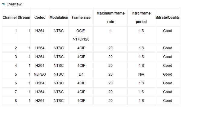
Click Overview at the top of the Audio and video window to see all current stream settings for each channel. See Figure 5-3.
Figure 5-3 Channel Stream Settings
Video Settings
You can choose from channels 1~4 or 8. Select one channel in the Channel drop-down list. You can then select video settings for that channel in the section below the drop-down list. Table 5-18 describes the Video settings.
Table 5-18 Video Settings
Check frame rate
Choose this to display the current available frame rate status for all frame sizes. For more information, see the "Available FPS" section.
Video title
The name you enter is displayed on the title bar of the live video.
Color
Choose to display color or black/white video streams.
Video orientation
Choose Flip (vertically reflects the display of the live video) or Mirror (horizontally reflects the display of the live video). Choose both options if the linked device is installed upside-down (for example, on the ceiling) to correct the image orientation.
Overlay title and time stamp on video and snapshot
Choose this option to place the video title and time on the video streams.
Enable time shift caching stream
This feature is available in Advanced Mode only.
Choose this item to enable the time shift cache stream on the encoder. This stores video in the embedded memory of the video server for a period of time depending on the cache memory size of each encoder. When an event occurs, the recording software can request time shift cache stream from the camera, which allows the user to retrieve pre-event video data.
Image Settings
This feature is available in Advanced Mode only.
For more information, see the "Image Settings" section.
Privacy Mask
This feature is available in Advanced Mode only.
For more information, see the "Privacy Mask" section.
Video Quality Settings for Stream 1
This feature is available in Advanced Mode only.
For more information, see the "Video Quality Settings for Stream 1" section.
Video Quality Settings for Stream 2
This feature is available in Advanced Mode only, and only on the CIVS-SENC-4P encoder model.
For more information, see the "Video Quality Settings for Stream 1" section.
Image Settings
Click Image Settings to open the Image Settings window. On this window, you can tune white balance, brightness, saturation, contrast, and sharpness settings for the video. Before tuning video settings, you must first choose a channel to which the settings will apply from the Channel drop-down list.
When you have finished with the settings on this window, click Save to enable the settings.
Table 5-19 describes the options available on the Image Settings window.
Note
Privacy Mask
You can add a masking window to the video feed to block out sensitive zones to address privacy concerns.
To add a privacy mask, perform the following procedure:
Procedure
Step 1
Step 2
Step 3
Step 4
Step 5
Step 6
Step 7
Note
•
•
Video Quality Settings for Stream 1
This feature is available in Advanced Mode only.
The CIVS-SENC-4P encoder model allows you to configure video quality settings for streams 1 and 2. The CIVS-SENC-8P model only permits the configuration of video quality settings for stream 1. For information about Available FPS data, see "Available FPS" section.
Table 5-20 describes the video quality settings for stream 1. The same settings also apply to stream 2 on the CIVS-SENC-4P encoder model.
Note
•
•
Available FPS
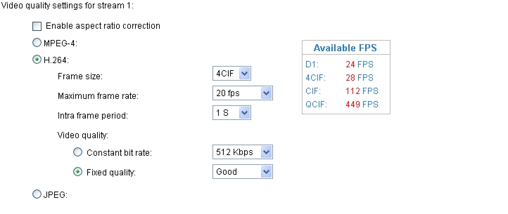
Choose the Check frame rate checkbox at the top of the Audio and video window to display the current available frame rate status (Available FPS). Available FPS provides information about the unused encoding capability, with available frame rates in different frame sizes. See Figure 5-4.
Figure 5-4 Available FPS
The embedded Soc (System-on-Chip) has limited encoding capability, so you may set the video quality according to the available FPS. Due to the limited encoding capability, the maximum frame rate that can be supported for 4CIF in H.264 or MPEG-4 codec is up to 24 FPS, when all channels are in use and have this setting applied. If the total frame rate exceeds encoding capability, a warning message "Frame rate is not guaranteed" is displayed in a pop-up window. Also, the frame rate that cannot be reached for each stream is marked in red in the Maximum frame rate drop-down list.
Audio Settings
Table 5-23 describes the audio settings.
Motion Detection Window
This section describes how to configure the encoder to enable motion detection by configuring motion detection windows. A total of three motion detection windows can be configured for each channel. For information about how motion detection works, see the "How Motion Detection Works" section.
To enable motion detection, perform the following procedure:
Procedure
Step 1
Step 2
Step 3
Step 4
Step 5
Step 6
Step 7
Step 8
Step 9
Step 10
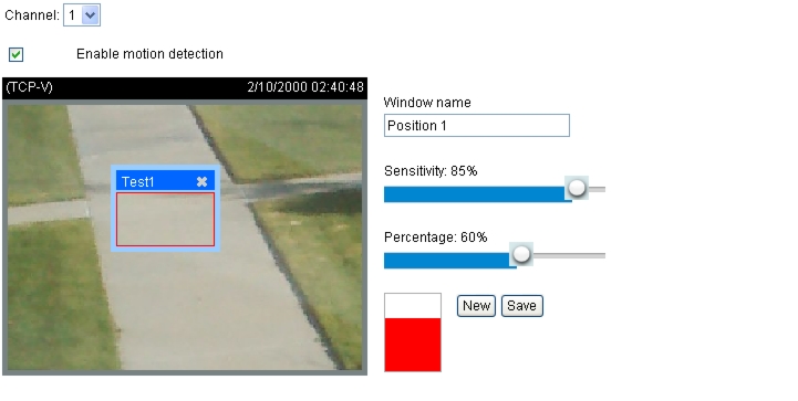
The percentage indicator rises or falls depending on the variation between sequential images. When motion is detected by the network camera and it is judged to exceed the defined threshold, the red bar rises. Meanwhile, the motion detection window is outlined in red. See Figure 5-5.
Photos or videos can be captured instantly and configured to be sent to a remote server (via Email or FTP) by using this feature as a trigger source. For more information about setting an event, see the "Application Window" section.
Figure 5-5 Motion Detection Window
A green bar indicates that even though motion has been detected, an event has not been triggered because the image variations still fall below the defined threshold.
The motion detection window is also displayed on the Event Settings window. To set a trigger event, choose Application > Event Settings > Trigger. For more information, see the "Event Settings" section.
How Motion Detection Works
There are two motion detection parameters: Sensitivity and Percentage. Sensitivity is a value that expresses sensitivity to moving objects, and percentage is a value that expresses the proportion of "alerted pixels" to the total number of pixels in a motion detection window.
Motion is represented by pixel differences between sequential frames within the area of a motion detection window. The pixel differences between two frames are first compared against the sensitivity setting. Higher sensitivity settings are expected to detect slight movements, while lower sensitivity settings neglect small movements. When the sensitivity is set to 85%, for example, the Network Camera defines even those pixels that have experienced only slight change as "alerted pixels". See Figure 5-5.
If, for example, the percentage is set to 60% and 85% of pixels are identified as "alerted pixels", as the motions are therefore judged to exceed the defined threshold, the motion window is outlined in red, and an event may be triggered.
For applications that require a high level of security management, it is suggested that you use higher sensitivity settings and lower percentage values.
Camera Tampering Detection Window
This section describes how to set up camera tampering detection. With tampering detection, the camera is capable of detecting incidents such as redirection, blocking or defocusing, or even spray painting.
To set up camera tampering detection, perform the following procedure:
Procedure
Step 1
Step 2
The alarm is triggered only when the tampering factor (the difference between current frame and pre-saved background) exceeds the trigger threshold.
Step 3
Step 4
Camera Control Window
This section describes how to control the Pan/Tilt/Zoom operation of the Network Camera by connecting to a PTZ driver or camera via RS485 interface. It includes the following topics:
•
For information about accessing the Camera control window, see the "Accessing Configuration Options" section.
When you have finished with the settings on this window, click Save to enable the settings.
RS485 Settings
Table 5-24 describes the RS485 settings:
Table 5-24 RS485 Settings
Disable
Choose this option to disable the camera control function.
PTZ camera
Choose this option to enable PTZ operation. To use this feature, connect the Network Camera to a PTZ driver or camera via an RS485 interface first. Table 5-25 describes the settings for configuring the PTZ driver and the RS485 port.
Transparent HTTP tunnel
If you want to use your own RS-485 device, you can use UART commands to build a Transparent HTTP Tunnel. The UART commands are sent through a HTTP tunnel established between the RS-485 device and the linked camera. Table 5-26 describes the Transparent HTTP tunnel settings
Camera ID Settings
The following five PTZ drivers are available:
•
•
•
•
•
Note
If none of the above PTZ drivers is supported by your PTZ camera, choose Custom camera in the PTZ driver drop-down list (see the PTZ camera entry in Table 5-25). Refer to the user guide of your PTZ camera to determine the Camera ID, PTZ driver, and Port settings. The Camera ID is required to control multiple cameras. When you click Save to enable this function, the camera control panel is displayed on the home window.
Customization Settings
This section contains the following topics:
•
•
Configuring Camera Preset Positions
If you select DynaDome/SmartDOME, Lilin PIH-7x00, Pelco D, Pelco P protocol, or Samsung scc643 protocol as the PTZ driver and click the Save button, the Preset position button at the bottom of the Camera control window is enabled. This button opens the Preset position window, from where you can configure up to 20 preset positions for the cameral.
To configure a preset position, perform the following procedure:
Procedure
Step 1
Step 2
•
•
•
•
•
Note
Step 3
Step 4
Step 5
The control functions are the same as those on the home window control panel. For more information, see the "Camera Control Area" section.
Step 6
Step 7
The preset positions are displayed in the User preset locations list.
Step 8
Step 9
Step 10
The saved preset positions are available in the Go to drop-down list on the Home window. See the "Home Window Overview" section.
Step 11
Configuring Camera Patrol Settings
You can select some preset positions for the Network Camera to patrol.
To set up a patrol schedule, perform the following procedure:
Procedure
Step 1
Step 2
Step 3
Step 4
.
The selected preset locations are displayed in the Patrol locations list.
Step 5
Step 6
Step 7
Step 8
Step 9
Configuring Custom Commands
If Custom camera is selected as the PTZ driver (see the PTZ camera entry in Table 5-25), the Preset position button on the Camera control window and the PTZ Control Panel on the home window are disabled. In this event, you must configure command buttons to control the PTZ camera.
To configure custom commands for the Network Camera, perform the following procedure:
Procedure
Step 1
Step 2
Note
Step 3
The Custom command dialog box appears.
Step 4
Refer to your PTZ camera user guide to find the commands to be entered in the Control settings and Custom command fields.
Note
•
•
Step 5
Step 6
The command buttons you set are displayed on the home window, below the live video.
Homepage Layout Window
This feature is available in Advanced Mode only.
This section explains how to set up your own customized home window layout, and it contains the following topics:
For information about accessing the Homepage layout window, see the "Accessing Configuration Options" section.
When you have finished with the settings on this window, click Save to enable the settings.
Preview Area
The Preview area gives you a preview of your home window layout settings. You can manually select the background and font colors in Theme Options (see the "Theme Options" section), and the updated settings are displayed automatically in the Preview area.
Customized Button
To display the manual trigger buttons on the home window, check the Show manual trigger checkbox. To hide this function, uncheck the Show manual trigger checkbox. For more information, see the "Manual Trigger Area" section.
Theme Options
You can choose either of the following options to customize your home window:
•
Use a Preset Theme
You can change the color scheme of your home window by choosing one of three preset themes that are listed in the Themes frame within Theme options. When you choose a new color scheme, it is displayed in the Preview area. Click Save to enable the settings.
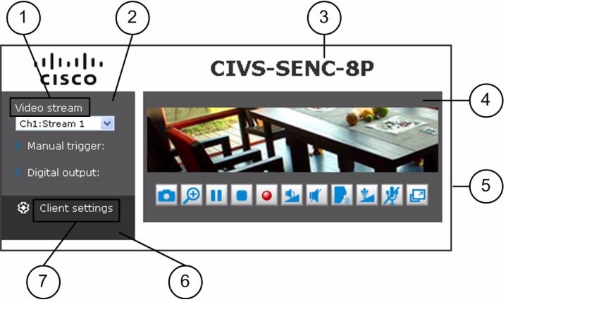
Create Your own Customizations
Figure 5-6 shows the areas of the home window that can be customized from Theme options.
Figure 5-6 Customizable Home Window Features
To customize your home window, perform the following procedure:
Step 1
Step 2
Step 3
The palette window is displayed.
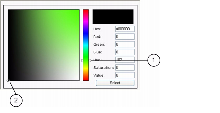
Step 4
Step 5
Figure 5-7 Palette Window
The new color is displayed in the Preview area.
Step 6
Step 7
Application Window
This feature is available in Advanced Mode only.
This section describes how to configure the encoder to respond to particular events. An event can be triggered by many sources, such as motion detection or external digital input devices. You can specify the type of action that is performed when a specific event is triggered, and the encoder can be configured to send snapshots or videos to your email address or FTP site. This section contains the following topics:
For information about accessing the Application window, see the "Accessing Configuration Options" section.
When you have finished with the settings on this window, click Save to enable the settings.
Event Settings
In the Event settings area, click Add to open the Event settings window. On this window, you can configure general event settings (see Table 5-27), as well as the following three key elements of an event:
Up to three event settings can be configured.
Event Trigger
The event trigger is the stimulus that defines when to trigger the encoder. The trigger source can also be configured to use the built-in motion detection mechanism of the encoder or external digital input devices.
Table 5-28 describes the trigger sources that you can choose in the Source drop-down list.
Table 5-28 Trigger Settings
Video motion detection
This option uses the built-in motion detection mechanism as a trigger source. To enable this function, you must first configure a Motion Detection Window. For more information, see the "Motion Detection Window" section.
Camera tampering detection
This option allows the encoder to trigger when the camera detects that is is being tampered with. To enable this function, you must first configure the Camera tampering detection option. For more information, see the "Camera Tampering Detection Window" section.
Video loss
This option triggers the encoder when the transmitted media files are missing. Check the appropriate channel fields to enable the trigger source for those channels.
Video restore
This option triggers the encoder when the camera starts to transmit video files.
Periodically
This option allows the encoder to trigger periodically every other defined minute. Enter the number of minutes in the Trigger every other n minute(s) field. Up to 999 minutes are allowed.
Digital input
This option allows the encoder to use an external digital input device or sensor as a trigger source. Depending on your application, you can choose from a wide selection of digital input devices that help to detect changes in temperature, vibration, sound, light, and so on.
System boot
This option triggers the encoder when the power to the encoder is disconnected.
Recording notify
This feature is available on CIVS-SENC-4P encoder model only.
This option allows the encoder to trigger when the recording disk is full or when recording begins to rewrite older data.
Manual trigger
This option allows users to enable event triggers manually by clicking the on/off button on the home window. You should configure one to three events before using this function.
Event Schedule
The Event schedule settings allow you to specify the period in which an event can occur. Table 5-29 describes the event schedule settings.
Event Action
An event action is an action to be performed by the encoder when a trigger is activated. Table 5-30 describes the Event action settings.
Table 5-30 Event Action Settings
Trigger digital output for
Where n is the number of seconds. Check the box beside the desired DO number to turn on a connected external digital output device when a trigger is activated. Enter the folowing information:
•
•
Move to preset location
Choose this option to make the Network Camera move to a preset location when a trigger is activated. You must first set up the preset locations. Click Preset locations to set up more preset locations for each channel, where each channel represents a Network Camera. For more information about preset locations settings, see the "Configuring Camera Preset Positions" section.
Server
To set up an event with recorded video or snapshots, you must configure the server settings so that the encoder knows what action to take (such as which server to send the media files to) when a trigger is activated. To configure server settings, click Server. For more information about configuring server settings, see the "Server Settings" section.
Media
To set up an event with recorded video or snapshots, you must configure the media settings so that the encoder knows what action to take when a trigger is activated. To configure media settings, click Media. For more information about configuring media settings, see the "Media Settings" section.
When you finish configuring event settings, click Save to enable the settings. Click Close to exit the Event settings window. The new Event settings, Server settings, and /or Media settings are displayed on the Application window.
After you configure a server or media type for an event, you can continue to select other servers and media types for the event. For more information, see the "Selecting a Server and Media Type for an Event" section.
Tip
Managing Event Settings on the Application Window
When the Event Status is ON, once an event is triggered by motion detection, the encoder sends snapshots via e-mail automatically.
You can perform the following actions from the Application window:
•
•
•
•
Server Settings
On the Server settings window, you can specify where notification messages are sent when a trigger is activated. To access the Server settings window, perform the following procedure:
Procedure
Step 1
Step 2
Step 3
Step 4
Step 5
•
•
When you finish, the new server settings are displayed automatically on the Event settings window.
Note
Choose this option to send the media files via email when a trigger is activated. Table 5-31 describes the Email settings.
To verify that the email settings are correctly configured, click Test. The result is displayed in a pop-up window. If successful, you will also receive an email indicating the result.
Click Save to enable your settings, then click Close to exit the window.
FTP
Choose this option to send the media files to an FTP server when a trigger is activated. Table 5-32 describes the FTP settings.
To verify that the FTP settings are correctly configured, click Test. The result is displayed in a pop-up window. If successful, you will also receive a test.txt file on the FTP server.
Click Save to enable the settings, then click Close to exit the window.
HTTP
Choose this option to send the media files to an HTTP server when a trigger is activated. Table 5-33 describes the HTTP settings.
Table 5-33 HTTP Settings
URL
The URL of the HTTP server.
User name
The user name, if required.
Password
The password, if required.
To verify that the HTTP settings are correctly configured, click Test. The result is displayed in a pop-up window. If successful, you will receive a test.txt file on the HTTP server.
Click Save to enable the settings, and then click Close to exit the window.
Network Storage
While Network Storage is shown on the user interface, it is not currently supported by Cisco.
Media Settings
On the Media settings window, you can specify the type of media that are sent when a trigger is activated. To access the Media settings window, perform the following procedure:
Procedure
Step 1
Step 2
Step 3
Step 4
Step 5
Snapshot
Choose this option to send snapshots when a trigger is activated. Table 5-34 describes the Snapshot settings.
Click Save to enable the settings, and then click Close to exit the window.
Video Clip
Choose this option to send video clips when a trigger is activated. Table 5-35 describes the Video Clip settings.
Table 5-35 Video Clip Settings
Channel
The video source. The stream source is identical to the preset time shift caching stream. For more information about the time shift caching stream, see the "Video Settings" section.
Pre-event recording
Enter a number to determine the amount of recording time to save before a trigger is activated. Up to nine seconds of video can be stored temporarily in the encoder buffer area.
Maximum duration
Specify the maximum recording duration in seconds. The encoder can record up to 10 seconds.
For example, if pre-event recording is set to five seconds and the maximum duration is set to ten seconds, the encoder continues to record for another 4 seconds after a trigger is activated.
Maximum file size
Specify the maximum file size allowed.
File name prefix
Enter the text that is appended to the front of the file name.
Click Save to enable the settings, and then click Close to exit the window.
System Log
Choose this option to send a system log when a trigger is activated. Click Save to enable the settings, and then click Close to exit the window.
Selecting a Server and Media Type for an Event
When you have configured your server and media type settings, you can proceed to select a server and media type for the event.
To select a server and media type, perform the following procedure:
Procedure
Step 1
Step 2
Step 3
Step 4
Step 5
Step 6
Recording Window
While Recording is shown on the user interface, it is not currently supported by Cisco.
Local Storage Window
While Local Storage is shown on the user interface, it is not currently supported by Cisco.
System Log Window
This feature is available in Advanced Mode only.
This section describes how to configure the encoder to send the system log to the remote server as backup.
The following logs are produced by the encoder:
For information about accessing the System log window, see the "Accessing Configuration Options" section.
When you have finished with the settings on this window, click Save to enable the settings.
Remote Log
You can configure the encoder to send the system log file to a remote server as a log backup.
Before using this feature, it is recommended that you install a log recording tool to receive system log messages from the encoder. For an example of a log recording tool, go to the Kiwi Syslog Daemon website at http://www.kiwisyslog.com/kiwi-syslog-daemon-overview/.
To set up a remote log, perform the following procedure:
Procedure
Step 1
Step 2
Step 3
Step 4
Current Log
The Current log area displays the system log in chronological order. The system log is stored in the encoder buffer area and is overwritten when a specific limit is reached.
View Parameters Window
This feature is available in Advanced Mode only.
The View Parameters window lists the parameters for the entire system in alphabetical order. If you need technical assistance, you may be asked to provide information listed on this window.
Maintenance Window
This section describes how to restore the video server to factory default, upgrade firmware version, etc, and includes the following topics:
•
Rebooting the Encoder
To reboot the encoder, perform the following procedure:
Procedure
Step 1
A message is displayed while the reboot is in progress. When the reboot is finished, the live video window is displayed in your browser.
Step 2
Restoring the Encoder
To restore the encoder to the factory default settings, perform the following procedure:
Procedure
Step 1
Step 2
Table 5-36 Restore Settings
Network type
Choose this option to retain the Network type settings. For more information about Network type settings, see the "Network Type Settings" section.
Daylight saving time
Choose this option to retain the Daylight saving time settings. For more information about Daylight saving time settings, see the "System Window" section.
Custom language
Choose this option to retain the Custom Language settings.
If none of the above options is selected, all settings are restored to factory default.
Step 3
The encoder reboots as part of the restore procedure, and a message is displayed while the reboot is in progress.
Step 4
Exporting and Uploading Files
This feature is available in Advanced Mode only.
This feature allows you to export and upload daylight saving time rules, custom language files, and setting backup files.
You can perform the following actions:
•
•
•
•
•
•
Exporting the Daylight Savings Time File Configuration
To export the daylight saving time configuration file from the encoder, perform the following procedure:
Procedure
Step 1
Step 2
A file download dialog box is displayed.
Step 3
Step 4
For information about uploading the daylight saving time rule, see the "Uploading Daylight Saving Time Rules" section.
Exporting the Language File
To export the language file from the encoder, perform the following procedure:
Procedure
Step 1
Step 2
A file download dialog box is displayed.
Step 3
For information about uploading a custom language file, see the "Uploading the Custom Language File" section.
Exporting the Setting Backup File
To export the setting backup file from the encoder, perform the following procedure:
Procedure
Step 1
Step 2
A file download dialog box is displayed.
Step 3
For information about uploading a setting backup file, see the "Uploading the Setting Backup File" section.
Uploading Daylight Saving Time Rules
To upload daylight saving time rules to the encoder, perform the following procedure:
Procedure
Step 1
Step 2
Step 3
If an incorrect date and time are assigned in the XML file, a warning message is displayed when the file is being uploaded to the encoder.
Uploading the Custom Language File
To upload a custom language file to the encoder, perform the following procedure:
Procedure
Step 1
Step 2
Step 3
Uploading the Setting Backup File
To upload a custom language file to the encoder, perform the following procedure:
Procedure
Step 1
Step 2
Step 3
Note
Upgrading the Firmware
This feature allows you to upgrade the firmware of your encoder.
WarningTo upgrade the firmware, perform the following procedure:
Procedure
Step 1
Step 2
Step 3
Step 4
The encoder starts to upgrade and reboots automatically when the upgrade is finished.
If the upgrade is successful, a message is displayed to inform you that the system is about to reboot immediately.
If you selected an incorrect firmware file, a message is displayed to inform you that the unpack procedure has failed.