-
Cisco ASA 5500 Series Configuration Guide using the CLI, 8.2
-
About This Guide
-
Glossary
- Getting Started and General Information
- Configuring Access Lists
- Configuring IP Routing
- Configuring NAT
- Configuring High Availability
- Configuring Access Control
- Configuring Application Layer Procotol Inspection
- Configuring Unified Communications
- Configuring Advanced Connection Settings
- Configuring Applications on SSMs and SSCs
-
Configuring VPN
-
Configuring IPSec and ISAKMP
-
Configuring L2TP over IPSec
-
Setting General VPN Parameters
-
Configuring Tunnel Groups, Group Policies, and Users
-
Configuring IP Addresses for VPN
-
Configuring Remote Access VPNs
-
Configuring Network Admission Control
-
Configuring Easy VPN on the ASA 5505
-
Configuring the PPPoE Client
-
Configuring LAN-to-LAN VPNs
-
Configuring Clientless SSL VPN
-
Configuring AnyConnect VPN Client Connections
-
Configuring Certificates
-
- Monitoring
- System Administration
- Reference
-
 Feedback
Table Of Contents
Enabling ICMP Debug Messages and System Log Messages
Pinging Security Appliance Interfaces
Pinging Through the Security Appliance
Disabling the Test Configuration
Recovering Passwords for the ASA
Recovering Passwords for the PIX 500 Series Security Appliance
Resetting the Password on the SSM Hardware Module
Using the ROM Monitor to Load a Software Image
Troubleshooting
This chapter describes how to troubleshoot the ASA, and includes the following sections:
•
Using the ROM Monitor to Load a Software Image
•
Testing Your Configuration
This section describes how to test connectivity for the single mode ASA or for each security context, how to ping the ASA interfaces, and how to allow hosts on one interface to ping through to hosts on another interface.
We recommend that you only enable pinging and debug messages during troubleshooting. When you are done testing the ASA, follow the steps in "Disabling the Test Configuration" section.
This section includes the following topics:
•
•
•
•
Enabling ICMP Debug Messages and System Log Messages
Debug messages and system log messages can help you troubleshoot why your pings are not successful. The ASA only shows ICMP debug messages for pings to the ASA interfaces, and not for pings through the ASA to other hosts. To enable debugging and system log messages, perform the following steps:
Examples
The following example shows a successful ping from an external host (209.165.201.2) to the ASA outside interface (209.165.201.1):
hostname(config)# debug icmp traceInbound ICMP echo reply (len 32 id 1 seq 256) 209.165.201.1 > 209.165.201.2Outbound ICMP echo request (len 32 id 1 seq 512) 209.165.201.2 > 209.165.201.1Inbound ICMP echo reply (len 32 id 1 seq 512) 209.165.201.1 > 209.165.201.2Outbound ICMP echo request (len 32 id 1 seq 768) 209.165.201.2 > 209.165.201.1Inbound ICMP echo reply (len 32 id 1 seq 768) 209.165.201.1 > 209.165.201.2Outbound ICMP echo request (len 32 id 1 seq 1024) 209.165.201.2 > 209.165.201.1Inbound ICMP echo reply (len 32 id 1 seq 1024) 209.165.201.1 > 209.165.201.2This example shows the ICMP packet length (32 bytes), the ICMP packet identifier (1), and the ICMP sequence number (the ICMP sequence number starts at 0 and is incremented each time that a request is sent).
Pinging Security Appliance Interfaces
To test whether the ASA interfaces are up and running and that the ASA and connected routers are operating correctly, you can ping the ASA interfaces. To ping the ASA interfaces, perform the following steps:
Step 1
Note
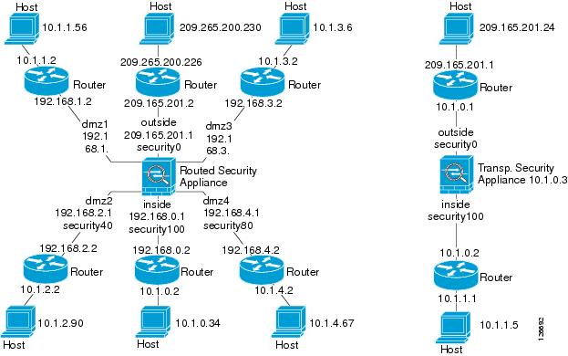
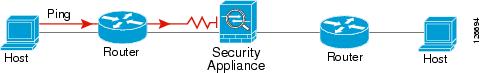
The diagram should also include any directly connected routers, and a host on the other side of the router from which you will ping the ASA. You will use this information in this procedure and in the procedure in "Pinging Through the Security Appliance" section. For example:
Figure 27-1 Network Diagram with Interfaces, Routers, and Hosts
Step 2
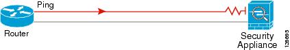
A ping might fail if the ASA interface is not active, the interface configuration is incorrect, or if a switch between the ASA and a router is down (see Figure 27-2). In this case, no debug messages or system log messages appear, because the packet never reaches the ASA.
Figure 27-2 Ping Failure at Security Appliance Interface
If the ping reaches the ASA, and the ASA responds, debug messages similar to the following appear:
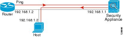
ICMP echo reply (len 32 id 1 seq 256) 209.165.201.1 > 209.165.201.2ICMP echo request (len 32 id 1 seq 512) 209.165.201.2 > 209.165.201.1If the ping reply does not return to the router, then a switch loop or redundant IP addresses may exist (see Figure 27-3).
Figure 27-3 Ping Failure Because of IP Addressing Problems
Step 3
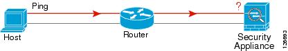
A ping might fail if the ASA does not have a return route to the host through the intermediate router (see Figure 27-4). In this case, the debug messages show that the ping was successful, but system log message 110001 appears, indicating a routing failure.
Figure 27-4 Ping Failure Because the Security Appliance has no Return Route
Pinging Through the Security Appliance
After you successfully ping the ASA interfaces, make sure traffic can pass successfully through the ASA. For routed mode, this test shows that NAT is operating correctly, if configured. For transparent mode, which does not use NAT, this test confirms that the ASA is operating correctly. If the ping fails in transparent mode, contact Cisco TAC.
To ping between hosts on different interfaces, perform the following steps:
Ping from the host or router through the source interface to another host or router on another interface.
Repeat this step for as many interface pairs as you want to check.
If the ping succeeds, a system log message appears to confirm the address translation for routed mode (305009 or 305011) and that an ICMP connection was established (302020). You can also enter either the show xlate or show conns command to view this information.
If the ping fails for transparent mode, contact Cisco TAC.
For routed mode, the ping might fail because NAT is not configured correctly (see Figure 27-5). This failure is more likely to occur if you enable NAT control. In this case, a system log message appears, showing that the NAT failed (305005 or 305006). If the ping is from an outside host to an inside host, and you do not have a static translation (required with NAT control), the following system log message appears: "106010: deny inbound icmp."
Note
Figure 27-5 Ping Failure Because the Security Appliance is not Translating Addresses
Disabling the Test Configuration
After you complete your testing, disable the test configuration that allows ICMP to and through the ASA and that prints debug messages. If you leave this configuration in place, it can pose a serious security risk. Debug messages also slow the ASA performance.
To disable the test configuration, perform the following steps:
Traceroute
You can trace the route of a packet using the traceroute feature, which is accessed with the traceroute command. A traceroute works by sending UDP packets to a destination on an invalid port. Because the port is not valid, the routers along the way to the destination respond with an ICMP Time Exceeded Message, and report that error to the security appliance.
Packet Tracer
In addition, you can trace the lifespan of a packet through the security appliance to see whether the packet is operating correctly with the packet tracer tool. This tool lets you do the following:
•
•
•
•
•
The packet-tracer command provides detailed information about the packets and how they are processed by the security appliance. If a command from the configuration did not cause the packet to drop, the packet-tracer command will provide information about the cause in an easily readable manner. For example, when a packet is dropped because of an invalid header validation, the following message appears: "packet dropped due to bad ip header (reason)."
Reloading the ASA
In multiple mode, you can only reload from the system execution space. To reload the ASA, enter the following command:
Performing Password Recovery
This section describes how to recover passwords if you have forgotten them or you are locked out because of AAA settings, and how to disable password recovery for extra security. This section includes the following topics:
•
•
•
Recovering Passwords for the ASA
To recover passwords for the ASA, perform the following steps:
Step 1
Step 2
Step 3
Step 4
rommon #1> confreg 0x41Update Config Register (0x41) in NVRAM...Step 5
rommon #1> confregThe ASA displays the current configuration register value, and asks whether you want to change it:
Current Configuration Register: 0x00000041Configuration Summary:boot default image from Flashignore system configurationDo you wish to change this configuration? y/n [n]: yStep 6
Step 7
The ASA prompts you for new values.
Step 8
Step 9
Step 10
rommon #2> bootLaunching BootLoader...Boot configuration file contains 1 entry.Loading disk0:/asa800-226-k8.bin... Booting...Loading...The ASA loads the default configuration instead of the startup configuration.
Step 11
hostname> enableStep 12
The password is blank.
Step 13
hostname# copy startup-config running-configStep 14
hostname# configure terminalStep 15
hostname(config)# password passwordhostname(config)# enable password passwordhostname(config)# username name password passwordStep 16
hostname(config)# no config-registerThe default configuration register value is 0x1. For more information about the configuration register, see the Cisco ASA 5500 Series Command Reference.
Step 17
hostname(config)# copy running-config startup-config
Recovering Passwords for the PIX 500 Series Security Appliance
Recovering passwords on the PIX 500 Series ASA erases the login password, enable password, and aaa authentication console commands. To recover passwords for the PIX 500 Series ASA, perform the following steps:
Step 1
Step 2
Step 3
Step 4
Step 5
monitor> interface interface_idmonitor> address interface_ipmonitor> server tftp_ipmonitor> file pw_tool_namemonitor> gateway gateway_ipStep 6
monitor> tftpdnldIf you have trouble reaching the server, enter the ping address command to test the connection.
Step 7
You can log in with the default login password of "cisco" and the blank enable password.
Examples
The following example shows password recovery on a PIX 500 Series ASA with the TFTP server on the outside interface:
monitor> interface 00: i8255X @ PCI(bus:0 dev:13 irq:10)1: i8255X @ PCI(bus:0 dev:14 irq:7 )Using 0: i82559 @ PCI(bus:0 dev:13 irq:10), MAC: 0050.54ff.82b9monitor> address 10.21.1.99address 10.21.1.99monitor> server 172.18.125.3server 172.18.125.3monitor> file np70.binfile np52.binmonitor> gateway 10.21.1.1gateway 10.21.1.1monitor> ping 172.18.125.3Sending 5, 100-byte 0xf8d3 ICMP Echoes to 172.18.125.3, timeout is 4 seconds:!!!!!Success rate is 100 percent (5/5)monitor> tftptftp np52.bin@172.18.125.3 via 10.21.1.1Received 73728 bytesCisco PIX password tool (4.0) #0: Tue Aug 22 23:22:19 PDT 2005Flash=i28F640J5 @ 0x300BIOS Flash=AT29C257 @ 0xd8000Do you wish to erase the passwords? [yn] yPasswords have been erased.Rebooting....Disabling Password Recovery
You might want to disable password recovery to ensure that unauthorized users cannot use the password recovery mechanism to compromise the ASA.
On the ASA, the no service password-recovery command prevents a user from entering ROMMON mode with the configuration intact. When a user enters ROMMON mode, the ASA prompts the user to erase all Flash file systems. The user cannot enter ROMMON mode without first performing this erasure. If a user chooses not to erase the Flash file system, the ASA reloads. Because password recovery depends on using ROMMON mode and maintaining the existing configuration, this erasure prevents you from recovering a password. However, disabling password recovery prevents unauthorized users from viewing the configuration or inserting different passwords. In this case, to restore the system to an operating state, load a new image and a backup configuration file, if available.
The service password-recovery command appears in the configuration file for information only. When you enter the command at the CLI prompt, the setting is saved in NVRAM. The only way to change the setting is to enter the command at the CLI prompt. Loading a new configuration with a different version of the command does not change the setting. If you disable password recovery when the ASA is configured to ignore the startup configuration at startup (in preparation for password recovery), then the ASA changes the setting to load the startup configuration as usual. If you use failover, and the standby unit is configured to ignore the startup configuration, then the same change is made to the configuration register when the no service password recovery command replicates to the standby unit.
On the PIX 500 series security appliance, the no service password-recovery command forces the PIX password tool to prompt the user to erase all Flash file systems. The user cannot use the PIX password tool without first performing this erasure. If a user chooses not to erase the Flash file system, the ASA reloads. Because password recovery depends on maintaining the existing configuration, this erasure prevents you from recovering a password. However, disabling password recovery prevents unauthorized users from viewing the configuration or inserting different passwords. In this case, to restore the system to an operating state, load a new image and a backup configuration file, if available.
Resetting the Password on the SSM Hardware Module
To reset the password to the default of "cisco" on the SSM hardware module, perform the following steps:
Note
Using the ROM Monitor to Load a Software Image
This section describes how to load a software image to an ASA from the ROM monitor mode using TFTP.
To load a software image to an ASA, perform the following steps:
Step 1
Step 2
Step 3
Step 4
rommon #1> ADDRESS=10.132.44.177rommon #2> SERVER=10.129.0.30rommon #3> GATEWAY=10.132.44.1rommon #4> IMAGE=f1/asa800-232-k8.binrommon #5> PORT=Ethernet0/0Ethernet0/0Link is UPMAC Address: 0012.d949.15b8
Note
Step 5
rommon #6> setROMMON Variable Settings:ADDRESS=10.132.44.177SERVER=10.129.0.30GATEWAY=10.132.44.1PORT=Ethernet0/0VLAN=untaggedIMAGE=f1/asa800-232-k8.binCONFIG=LINKTIMEOUT=20PKTTIMEOUT=4RETRY=20Step 6
rommon #7> ping serverSending 20, 100-byte ICMP Echoes to server 10.129.0.30, timeout is 4 seconds:Success rate is 100 percent (20/20)Step 7
rommon #8> tftpROMMON Variable Settings:ADDRESS=10.132.44.177SERVER=10.129.0.30GATEWAY=10.132.44.1PORT=Ethernet0/0VLAN=untaggedIMAGE=f1/asa800-232-k8.binCONFIG=LINKTIMEOUT=20PKTTIMEOUT=4RETRY=20tftp f1/asa800-232-k8.bin@10.129.0.30 via 10.132.44.1Received 14450688 bytesLaunching TFTP Image...Cisco PIX Security Appliance admin loader (3.0) #0: Mon Mar 5 16:00:07 MST 2007Loading...After the software image is successfully loaded, the adaptive security appliance automatically exits ROMMOM mode.
Step 8
hostname> show version
Erasing the Flash File System
Step 1
Step 2
Step 3
Step 4
rommon #1> erase [disk0: | disk1: | flash:]
Other Troubleshooting Tools
The ASA provides other troubleshooting tools that you can use. This section includes the following topics:
Viewing Debug Messages
Because debugging output is assigned high priority in the CPU process, it can render the system unusable. For this reason, use debug commands only to troubleshoot specific problems or during troubleshooting sessions with Cisco TAC. Moreover, it is best to use debug commands during periods of less network traffic and fewer users. Debugging during these periods decreases the likelihood that increased debug command processing overhead will affect system use. To enable debug messages, see the debug commands in the Cisco ASA 5500 Series Command Reference.
Capturing Packets
Capturing packets is sometimes useful when troubleshooting connectivity problems or monitoring suspicious activity. We recommend contacting Cisco TAC if you want to use the packet capture feature. See the capture command in the Cisco ASA 5500 Series Command Reference.
Viewing the Crash Dump
If the ASA crashes, you can view the crash dump information. We recommend contacting Cisco TAC if you want to interpret the crash dump. See the show crashdump command in the Cisco ASA 5500 Series Command Reference.
Coredump
A coredump is a snapshot of the running program when the program has terminated abnormally —crashed. Coredumps are used to diagnose or debug errors and save a crash for later off-site analysis. Cisco TAC may request that users enable the coredump feature to troubleshoot application or system crashes on the ASA. See the coredump command in the Cisco ASA 5500 Series Command Reference
Common Problems
This section describes common problems with the ASA, and how you might resolve them.
Symptom The context configuration was not saved, and was lost when you reloaded.
Possible Cause You did not save each context within the context execution space. If you are configuring contexts at the command line, you did not save the current context before you changed to the next context.
Recommended Action Save each context within the context execution space using the copy start run command. Load the startup configuration as your active configuration. Then change the password and then enter the copy run start command. You cannot save contexts from the system execution space.
Symptom You cannot make a Telnet or SSH connection to the ASA interface.
Possible Cause You did not enable Telnet or SSH to the ASA.
Recommended Action Enable Telnet or SSH to the ASA according to the instructions in "Allowing Telnet Access" section or the "Allowing SSH Access" section.
Symptom You cannot ping the ASA interface.
Possible Cause You disabled ICMP to the ASA.
Recommended Action Enable ICMP to the ASA for your IP address using the icmp command.
Symptom You cannot ping through the ASA, although the access list allows it.
Possible Cause You did not enable the ICMP inspection engine or apply access lists on both the ingress and egress interfaces.
Recommended Action Because ICMP is a connectionless protocol, the ASA does not automatically allow returning traffic through. In addition to an access list on the ingress interface, you either need to apply an access list to the egress interface to allow replying traffic, or enable the ICMP inspection engine, which treats ICMP connections as stateful connections.
Symptom Traffic does not pass between two interfaces on the same security level.
Possible Cause You did not enable the feature that allows traffic to pass between interfaces at the same security level.
Recommended Action Enable this feature according to the instructions in "Allowing Same Security Level Communication" section.
Symptom IPSec tunnels do not duplicate during a failover to the standby device.
Possible Cause The switch port that the ASA is plugged into is set to 10/100 instead of 1000.
Recommended Action Set the switch port that the ASA is plugged into to 1000.