-
Cisco 2800 Series Hardware Installation
-
Installing and Upgrading Fans in Cisco 2811 Series Routers
-
Cisco 2800 Series Hardware Documents: Introduction and Warnings
-
Overview of Cisco 2800 Series Routers
-
Pre-Installation Requirements and Planning for Cisco 2800 Series Routers
-
Port and Cable Information for Cisco 2800 Series Routers
-
Chassis Installation Procedures for Cisco 2800 Series Routers
-
Cable Connection Procedures for Cisco 2800 Series Routers
-
Power-Up Procedures for Cisco 2800 Series Routers
-
Troubleshooting Cisco 2800 Series Routers
-
Installing Network Modules in Cisco 2800 Series Routers
-
Installing Interface Cards in Cisco 2800 Series Routers
-
Installing and Upgrading Internal Modules in Cisco 2800 Series Routers
-
Removing and Installing CompactFlash Memory Cards in Cisco 2800 Series Routers
-
 Feedback
Table Of Contents
Cable Connection Procedures for Cisco 2800 Series Routers
Connecting Routers to AC Power
Connecting Routers to DC Power
Connecting Routers to Backup Power
Connecting WAN, LAN, and Voice Cables
Connection Procedures and Precautions
Connecting to a Console Terminal or Modem
Connecting to the Console Port
Connecting to the Auxiliary Port
Cable Connection Procedures for Cisco 2800 Series Routers
This document describes how to connect your Cisco 2800 series integrated services router to a power source and to networks and external devices. It includes the following sections:
•
Connecting WAN, LAN, and Voice Cables
•
Note
Warning
WarningPower Connections
This section explains how to connect AC or DC power to Cisco 2800 series routers. It covers the following topics:
•
•
•
Warning
Note
Connecting Routers to AC Power
If your router uses AC power, connect it to a 15 A, 120 VAC (10 A, 240 VAC) circuit with overcurrent protection. If backup power is required, see the "Connecting Routers to Backup Power" section.
Note
WarningConnecting Routers to DC Power
Note
Warning
60 VDC, 20 A. Statement 1005
WarningIf your router has a DC-input power supply, follow the directions in this section for proper wiring. A router with a DC-input power supply has a terminal block for the DC power connections. If backup power is required, see the "Connecting Routers to Backup Power" section.
DC Wiring Requirements
A Cisco 2811, Cisco 2821, or Cisco 2851 router with a DC-input power supply requires copper wire and crimp-type terminals for the power connections. Table 1 and Table 2 summarize the wiring requirements.
You can connect a single DC power source to either the A input or the B input. If there are dual power sources, connect one source to the A input and one source to the B input; both sources must be the same polarity and voltage.
Wiring Procedure for DC Input
To connect a router to a DC power source, perform the following steps:
Step 1
Warning
Tip
Step 2
Step 3
Step 4
Step 5
Caution
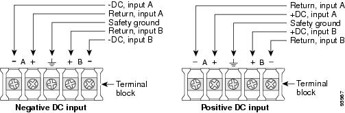
Figure 1 DC Power Connections for Cisco 2800 Series Routers
Step 6
Step 7
Step 8
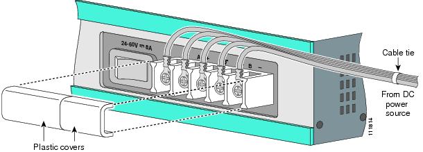
Figure 2 Wire Routing and Attachment for Cisco 2811 Routers
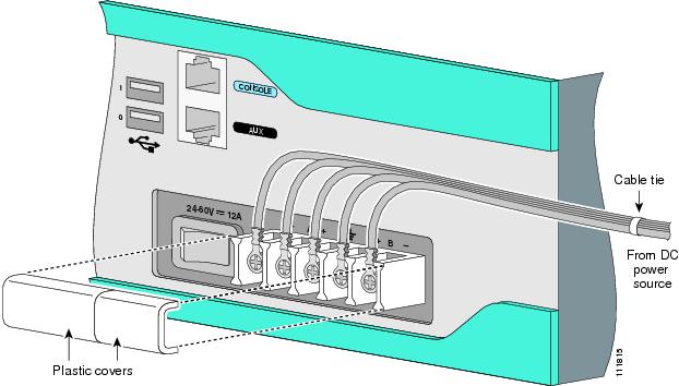
Figure 3 Wire Routing and Attachment for Cisco 2821 and Cisco 2851 Routers
Approved Scenarios and Scenarios Not Approved for Dual DC Power Supply Configuration in Cisco 2800 Routers
You can connect a single DC power source to either the A input or the B input. If there are dual power sources, connect one source to the A input and one source to the B input. Both sources must be the same polarity (with respect to ground) and voltage (within 0.25 volts). Do not connect -DC grounded and +DC grounded dual sources to Cisco 2811, Cisco 2821, and Cisco 2851 routers.
Caution
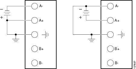
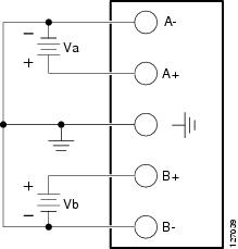
In Figure 4, either the positive source terminal or the negative source terminal is tied to ground.
Figure 4 Connecting to One Source Only—Source A or Source B
In Figure 5, source A and source B share common negative terminal connections.
Figure 5 Connecting Source A and Source B with Common Negative Terminals
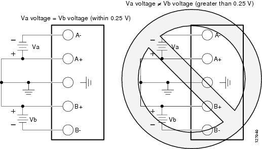
In Figure 6, source A and source B share common positive terminal connections. This is allowed only if Va equals Vb (within 0.25 V).
Caution
Note
Figure 6 Connecting Source A and Source B with Common Positive Terminals
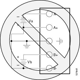
In Figure 7, source A and source B are wired with opposite polarity grounds. Do not use this configuration.
Figure 7 Source A and Source B Wired with Opposite-Polarity Grounds
Connecting Routers to Backup Power
If your router uses the Cisco Redundant Power System (RPS), refer to the Cisco Redundant Power System Hardware Installation Guide for instructions about the power connections. You can access this document at:
http://www.cisco.com/en/US/docs/routers/access/rps/hardware/installation/guide/rpshim.html.
Caution
Note
Connecting WAN, LAN, and Voice Cables
This section describes how to connect the WAN, LAN, and voice interface cables. It covers the following topics:
•
One or two Ethernet cables are typically provided with the router. Additional cables and transceivers can be ordered from Cisco. For ordering information, contact customer service. For cable pinouts, refer to the Cisco Modular Access Router Cable Specifications document.
WarningPorts and Cabling
Table 3 summarizes some typical WAN, LAN, and voice connections for Cisco 2800 series routers. The connections summarized here are also described in detail in the following documents:
•
•
•
Table 3 WAN, LAN, and Voice Connections
Ethernet
RJ-45, yellow
Ethernet hub or Ethernet switch
Category 5 or higher Ethernet
T1/E1 WAN
xCE1T1-PRIRJ-48C/CA81A
RJ-48S, tanT1 or E1 network
External T1 CSU or other T1 equipmentRJ-48 T1/E1
RJ-48S to RJ-48S TE
RJ-48S to RJ-48S NT
RJ-48S to RJ-48S T1
RJ-48S to bare
RJ-48S to BNC
RJ-48S to twinaxial cable
RJ-48S to DB-15
RJ-48S to DB-15 nullT3/DS3/E3 WAN
BNC connector
T3 network, CSU/DSU, or other T3/DS3 equipment
75-ohm coaxial cable
Cisco serial
60-pin D-sub, blue
CSU/DSU and serial network or equipment
Cisco serial transition cable that matches the signaling protocol (EIA/TIA-232, EIA/TIA-449, V.35, X.21, or EIA-530)
and the serial port operating mode (DTE or DCE).2Cisco Smart serial
Cisco Smart compact connector, blue
CSU/DSU and serial network or equipment
ADSL
RJ-11C/CA11A, lavender
Network demarcation device for service provider DSL interface
RJ-11 straight-through
SHDSL
RJ-11C/CA11A, lavender, RJ-14
Network demarcation device for service provider DSL interface
RJ-11 straight-through for 2-wire
RJ-14 straight-through for 4-wireT1/E1 digital voice
RJ-48C/CA81A, tan
Digital PBX, ISDN network, CSU/DSU
RJ-48 T1/E1
Analog voice FXS
RJ-11, gray
Telephone, fax
RJ-11; RJ21 if using NM-HDA, straight-through
Analog voice FXO
RJ-11, pink
Central office, analog PBX
Analog voice E&M
RJ-45, brown
Analog PBX
RJ-45
BRI S/T WAN
(external NT1)RJ-45/CB-1D, orange
NT1 device or private integrated network exchange (PINX)
RJ-45 straight-through
BRI U WAN
(built-in NT1)RJ-49C/CA-A11, red
ISDN network
RJ-48 straight-through
56/64-kbps DSU/CSU
8-pin modular, blue
RJ-48S interface in subrate device or network
RJ-48 straight-through
T1/FT1 DSU/CSU
8-pin modular, blue
RJ-48C interface
RJ-48 straight-through
Gigabit Ethernet SFP, optical
LC, color according to optical wavelength
1000BASE-SX, -LX, -LH, -ZX, -CWDM
Optical fiber as specified on applicable data sheet
Gigabit Ethernet SFP, copper
RJ-45
1000BASE-T
Category 5, 5e, 6 UTP
1 Cable color codes are specific to Cisco cables.
2 See the Cisco Modular Access Router Cable Specifications document for information about choosing these cables.
Connection Procedures and Precautions
Connect each WAN, LAN, and voice cable to the appropriate connector on the chassis or on a network module or interface card.
•
•
•
•
For cable pinouts, refer to the Cisco Modular Access Router Cable Specifications document.
Connecting to a Console Terminal or Modem
Your router has asynchronous serial console and auxiliary ports for system management. These ports provide administrative access to your router either locally (with a console terminal or PC) or remotely (with a modem).
Cisco provides the following cables for connecting your router to a console terminal, PC, or modem:
•
•
•
This section describes how to connect a console terminal or PC to the console port and how to connect a modem to the auxiliary port. Table 4 summarizes the system management connections.
For information about cable pinouts, refer to the Cisco Modular Access Router Cable Specifications document.
Connecting to the Console Port
If a console terminal or PC is connected to the console port, you can configure the router locally. To connect a console terminal or a PC running HyperTerminal or similar terminal emulation software to the console port on the router, perform the following steps:
Step 1
Note
Step 2
Note
Connecting to the Auxiliary Port
If a modem is connected to the auxiliary port, a remote user can dial in to the router and configure it. To connect a modem to the auxiliary port on the router, perform the following steps:
Step 1
Step 2
Copyright © 2004 Cisco Systems, Inc. All rights reserved.