-
Cisco 2800 Series Hardware Installation
-
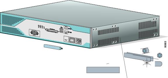
Installing and Upgrading Fans in Cisco 2811 Series Routers
-
Cisco 2800 Series Hardware Documents: Introduction and Warnings
-
Overview of Cisco 2800 Series Routers
-
Pre-Installation Requirements and Planning for Cisco 2800 Series Routers
-
Port and Cable Information for Cisco 2800 Series Routers
-
Chassis Installation Procedures for Cisco 2800 Series Routers
-
Cable Connection Procedures for Cisco 2800 Series Routers
-
Power-Up Procedures for Cisco 2800 Series Routers
-
Troubleshooting Cisco 2800 Series Routers
-
Installing Network Modules in Cisco 2800 Series Routers
-
Installing Interface Cards in Cisco 2800 Series Routers
-
Installing and Upgrading Internal Modules in Cisco 2800 Series Routers
-
Removing and Installing CompactFlash Memory Cards in Cisco 2800 Series Routers
-
 Feedback
Table Of Contents
Overview of Cisco 2800 Series Routers
Product Serial Number Location
Cisco Product Identification Tool
Removable and Interchangeable Modules
Cisco 2800 Series Router Installation and Preventive Maintenance
Cisco 2821 and Cisco 2851 Chassis
Overview of Cisco 2800 Series Routers
The Cisco 2800 series of integrated services routers offers secure, wire-speed delivery of concurrent data, voice, and video services. The modular design of the Cisco 2800 series routers provides maximum flexibility, allowing you to configure your router to meet evolving needs. The Cisco 2800 series routers incorporate data, security, and voice services in a single system for fast, scalable delivery of crucial business applications. The routers offer features such as hardware-based VPN encryption acceleration, intrusion-protection and firewall functions, and optional integrated call processing and voice mail. The routers offer a wide variety of network modules and interfaces, voice digital signal processor (DSP) slots, high-density interfaces for a wide range of connectivity requirements, and sufficient performance and slot density for future network expansion requirements and advanced applications.
The Cisco 2800 series consists of four versions. The Cisco 2801 routers and Cisco 2811 routers are one rack unit in height and have two 10/100 LAN ports. The more powerful Cisco 2821 routers and Cisco 2851 routers are two rack units in height and have two 10/100/1000 LAN ports. The higher-end router platforms of the Cisco 2800 series offer increased performance, increased slot density including network module slots ad extension voice module slots and increased inline power output.
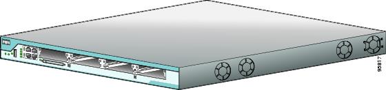
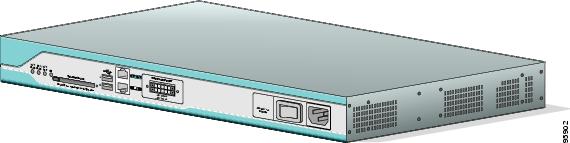
Figure 1, Figure 2, and Figure 3 show front views of the Cisco 2800 series routers.
Figure 1 Front View of a Cisco 2801 Router
Figure 2 Front View of a Cisco 2811 Router
Figure 3 Front View of a Cisco 2821 or Cisco 2851 Router
This chapter describes the features and specifications of the routers and includes the following sections:
Hardware Features
This section describes the basic features of Cisco 2800 series routers, including product identification, built-in interfaces, modules, memory, LED indicators, chassis ventilation, and the internal clock.
Product Serial Number Location
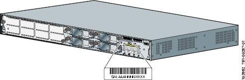
The serial number label for Cisco 2801 routers is located on the rear of the chassis, along the bottom edge near the lower left corner. (See Figure 4.)
Figure 4 Serial Number Location on the Cisco 2801 Router
Note
The serial number for Cisco 2801 routers is 11 characters long.
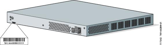
The serial number label for Cisco 2811 routers is located on the rear of the chassis, near the top right corner, to the left of the CLEI label. (See Figure 5.)
Figure 5 Serial Number Location on the Cisco 2811 Router
Note
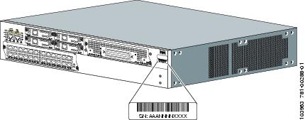
The serial number label for Cisco 2821 and Cisco 2851 routers is located on the rear of the chassis, near the top right corner, below the CLEI label. (See Figure 6.)
Figure 6 Serial Number Location on the Cisco 2821 and Cisco 2851 Routers
Note
Cisco Product Identification Tool
The Cisco Product Identification (CPI) tool provides detailed illustrations and descriptions showing where to locate serial number labels on Cisco products. It includes the following features:
•
•
•
The tool streamlines the process of locating serial number labels and identifying products. Serial number information expedites the entitlement process and is important for access to support services.
The Cisco Product Identification tool can be accessed at the following URL:
http://tools.cisco.com/Support/CPI/index.do
Built-in Interfaces
Table 1 summarizes the interface ports built into the chassis.
Removable and Interchangeable Modules
Table 2 summarizes the optional modules that can be installed in the router to provide specific capabilities. The network modules, extension voice modules, and interface cards fit into slots, located on the front of the chassis on the Cisco 2801 router, and on the rear of the chassis on the Cisco 2811, Cisco 2821, and Cisco 2851 routers; they can be removed and installed without opening the chassis. Advanced integration modules (AIMs), expansion DRAM memory modules (DIMMs), and packet voice data modules (PVDMs) plug into connectors inside the chassis; they can be removed and installed only by opening the chassis.
Table 2 Summary of Cisco 2800 Series Removable and Interchangeable Modules
Cisco 2801
—
2 single-wide (HWIC) or
2 double-wide (HWIC-D)1 WIC/VWIC/VIC slot
1 VWIC/VIC (voice-only)
—
2
2
Cisco 2811
1 network module (NM) or
1 network module enhanced (NME)
4 single-wide (HWIC) or
2 double-wide (HWIC-D)
—
2
2
Cisco 2821
1 network module (NM) or
1 network module enhanced (NME) or
1 network module enhanced extended (NME-X)
4 single-wide (HWIC) or
2 double-wide (HWIC-D)
1
2
3
Cisco 2851
1 network module (NM) or
1 network module enhanced (NME) or
1 network module enhanced extended (NME-X) or
1 network module double-wide (NMD) or
1 network module enhanced extended double-wide (NME-XD)
4 single-wide (HWIC) or
2 double-wide (HWIC-D)
1
2
3
1 Cisco 2800 series routers use PVDM II modules that are not compatible with Cisco 2600 series routers.
Memory
Cisco 2800 series routers contain the following types of memory:
•
•
•
Table 3 summarizes the memory options for Cisco 2800 series routers. The default memory numbers for RAM represent the minimum usable memory. You can install additional RAM in multiples of the default amount, up to the maximum amount.
Table 3 Router Memory Specifications
Cisco 2801
Type—SDRAM DIMM
DIMM sizes—64 MB, 128 MB, 256 MB
DIMM expansion slots—11
Default onboard memory—128 MB
Maximum memory—384 MB
Internal 4-MB flash memory
External CompactFlash memory cards of the following optional sizes:
•
•
Cisco 2811
Type—ECC DDR (error-correcting code, double data rate) SDRAM DIMM
DIMM sizes—256 MB, 512 MB
DIMM slots—2
Default onboard memory— none
Default memory—256 MB
Maximum memory—768 MB2
Internal 2-MB flash memory
External CompactFlash memory cards of the following optional sizes:
•
•
•
Cisco 2821
Type—ECC DDR (error-correcting code, double data rate) DRAM DIMM
DIMM sizes—256 MB, 512 MB
DIMM slots—2
Default onboard memory— none
Default memory—256 MB
Maximum memory—1024 MB3
Cisco 2851
1 Cisco 2801 routers have 128 MB of SDRAM soldered onto the system board. You can install a DIMM into the expansion slot to increase memory to the maximum of 384 MB.
2 Cisco 2811 routers can accept one 256 MB and one 512 MB DIMM to provide 768 MB of usable memory.
3 Cisco 2851 routers can accept two 512 MB DIMMs to provide 1024 MB of usable memory.
Power
Table 4 summarizes the power options for Cisco 2800 series routers. Cisco 2801 routers are equipped for operation using AC power only. Cisco 2811, Cisco 2821, and Cisco 2851 routers can be equipped for operation using either AC or DC input power by installation of the appropriate chassis power supply. IP phone power is supported if the appropriate AC-input chassis power supply is installed.
LED Indicators
Table 5 and Table 6 summarize the LED indicators that are located in the router bezel or chassis, but not in removable modules or interface cards.
To see descriptions of LEDs in removable modules and interface cards, refer to the applicable documentation for those products: the Cisco Network Modules Hardware Installation Guide or the Cisco Interface Cards Installation Guide.
For LED troubleshooting information, including possible trouble causes and corrective actions, see Table 1 in the "Troubleshooting Cisco 2800 Series Routers" document.
Table 6 Summary of Cisco 2811, Cisco 2821, and Cisco 2851 Series LED Indicators
Front of chassis
SYS
PWRSolid green
System is operating normally
Blinking green
System is booting or is in ROM monitor mode
Amber
System error
Off
Power is off or system board is faulty
AUX/
PWRGreen
IP phone power operating normally (if installed), or
Cisco Redundant Power System (RPS) operating normally (if installed)
Amber
IP phone power fault (if installed), or
Cisco Redundant Power System (RPS) fault (if installed)
Off
IP phone power and Cisco RPS are not installed
SYS
ACTBlinking green or solid green
Packet transfers are occurring
Off
No packet transfers are occurring
CF
Green
Flash memory is being accessed; do not eject the CompactFlash memory card
Off
Flash memory is not being accessed; okay to eject the CompactFlash memory card
Rear of chassis
A (=ACT)
Blinking green or solid green
Packet activity in FE or GE port
Off
No packet activity in FE or GE port
F (=FDX)
Green
FE or GE port is operating in full-duplex mode
Off
FE or GE port is operating in half-duplex mode
S (= Speed)1
1 blink + pause
FE or GE port operating at 10 Mbps
2 blinks + pause
FE or GE port operating at 100 Mbps
3 blinks + pause
GE port operating at 1000 Mbps (Cisco 2821 and Cisco 2851 only)
L (= Link)
Green
FE or GE link is established
Off
No FE or GE link is established
PVDM0
PVDM1
PVDM22
Green
PVDM in slot (0, 1, or 2) is initialized
Amber
PVDM in slot (0, 1, or 2) is detected but not initialized
Off
No PVDM installed in slot (0, 1, or 2)
AIM0
AIM1
Green
AIM in slot (0 or 1) is initialized
Amber
AIM in slot (0 or 1) has initialization error
Off
No AIM installed in slot (0 or 1)
1 The Ethernet S (Speed) LED blinks only when the L (Link) LED is on.
2 The PVDM2 LED is applicable only to the Cisco 2821 and Cisco 2851 routers.
Chassis Ventilation
Internal multispeed fans provide chassis cooling, controlled by an onboard temperature sensor.
The Cisco 2801 router has two fans. The Cisco 2801 router with inline power includes two additional fans integrated with the inline power supply, for a total of four fans. The Cisco 2801 internal fans operate at three different speeds, running at the slower speeds to conserve power and reduce fan noise at ambient temperatures below 40oC. They operate at the highest speed in ambient temperatures above 40oC.
The Cisco 2811 router has three fans that operate at a slower speed to conserve power and reduce fan noise at ambient temperatures below 32oC. They operate at high speed in ambient temperatures above 32oC.
The Cisco 2821 and Cisco 2851 routers have three fans that operate at a slower speed to conserve power and reduce fan noise at ambient temperatures below 40oC. They operate at high speed in ambient temperatures above 40oC.
Caution
Caution
Cisco 2800 Series Router Installation and Preventive Maintenance
Periodic inspection and cleaning of the external surface of the router is recommended to minimize the negative impact of environmental dust or debris on the router performance. The frequency of inspection and cleaning is dependent upon the severity of the environmental conditions. Cleaning involves vacuuming of router air intake and exhaust vents.
Caution
Real-Time Clock
An internal real-time clock with battery backup provides the system software with time of day on system power up. This allows the system to verify the validity of the certification authority (CA) certificate. In the Cisco 2811, Cisco 2821, and Cisco 2851 routers, the clock and battery are permanently installed; the battery lasts the life of the router under the operating environmental conditions specified for the router. The Cisco 2801 router has a socketed lithium battery. This battery lasts the life of the router under the operating environmental conditions specified for the router, and is not field-replaceable.
Note
Although the battery is not intended to be field-replaceable, the following warning must be heeded:
Chassis Views
This section contains views of the front and rear panels of the Cisco 2800 series routers, showing locations of the power and signal interfaces, module slots, status indicators, and chassis identification labels.
Cisco 2801 Chassis
Figure 7 shows the front panel of a Cisco 2801 router. Figure 8 shows the back panel.
Figure 7 Front Panel of the Cisco 2801 Router
Double-wide HWICs can go into slots 0 and 1, and into slots 2 and 3.
Note
Figure 8 Back Panel of the Cisco 2801 Router
Cisco 2811 Chassis
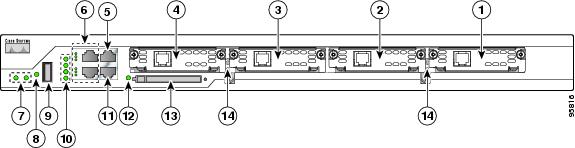
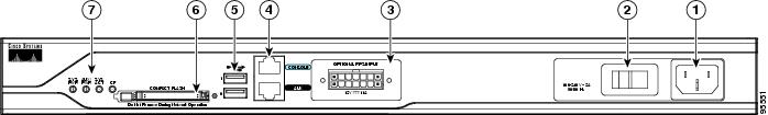
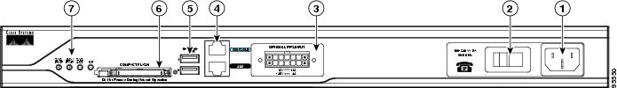
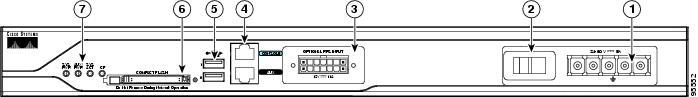
Figure 9, Figure 10, and Figure 11 show the front panel of a Cisco 2811 router. Figure 12 shows the rear panel of a Cisco 2811 router.
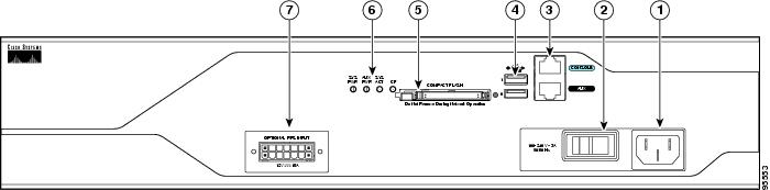
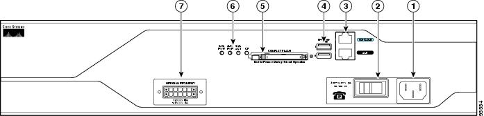
Figure 9 Front Panel of Cisco 2811 Router with AC Input Power and Without IP Phone Power Output
Figure 10 Front Panel of Cisco 2811 Router with AC Input Power and with IP Phone Power Output
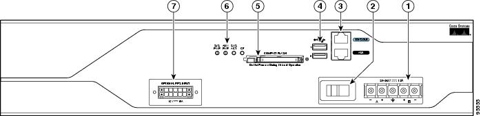
Figure 11 Front Panel of Cisco 2811 Router with DC Input Power
Input power connection
Universal serial bus (USB) ports
On/Stand-by switch1
External CompactFlash memory card slot
Cisco redundant power supply connector (covered if not used)
LED indicators
Console and auxiliary ports
1 This switch does not turn off the power supply completely, but rather puts it in stand-by mode.
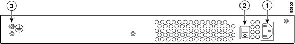
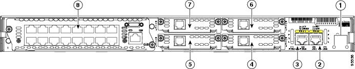
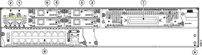
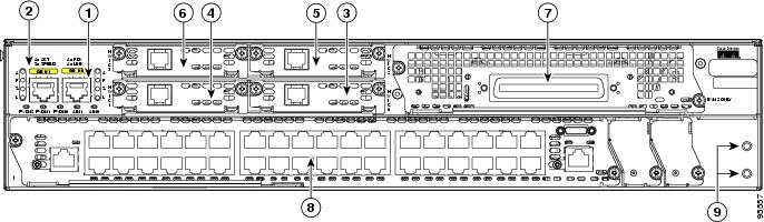
Figure 12 Rear Panel of Cisco 2811 Router
Screw holes for ground lug
High-speed WAN interface card slot 1
Fast Ethernet port 0/0
High-speed WAN interface card slot 2
Fast Ethernet port 0/1
High-speed WAN interface card slot 3
High-speed WAN interface card slot 0
Network module enhanced (NME) slot1
1 The network module slot is compatible with Cisco network modules of type NM (network module) and NME (network module enhanced).
Cisco 2821 and Cisco 2851 Chassis
Figure 13, Figure 14, and Figure 15 show the front panel of Cisco 2821 and Cisco 2851 routers. Figure 16 shows the rear panel of a Cisco 2821 router. Figure 17 shows the rear panel of a Cisco 2851 router.
Figure 13 Front Panel of Cisco 2821 and Cisco 2851 Routers with AC Input Power and Without IP Phone Power Output
Figure 14 Front Panel of Cisco 2821 and Cisco 2851 Routers with AC Input Power and IP Phone Power Output
Figure 15 Front Panel of Cisco 2821 and Cisco 2851 Routers with DC Input Power
Input power connection
External CompactFlash memory card slot
On/Standby switch1
LED indicators
Console and auxiliary ports
Cisco redundant power supply connector (covered if not used)
Universal serial bus (USB) ports
1 This switch does not turn off the power supply completely, but rather puts it in standby mode.
Figure 16 Rear Panel of the Cisco 2821 Router
Gigabit Ethernet port 0/0
High-speed WAN interface card slot 3
Gigabit Ethernet port 0/1
Extension voice module (EVM) slot
High-speed WAN interface card slot 0
Network module enhanced (NME) slot1
High-speed WAN interface card slot 1
Screw holes for ground lug
High-speed WAN interface card slot 2
1 The network module slot is compatible with Cisco network modules of type NM (network module), NME (network module enhanced), and NME-X (enhanced extended).
Figure 17 Rear Panel of the Cisco 2851 Router
Gigabit Ethernet port 0/0
High-speed WAN interface card slot 3
Gigabit Ethernet port 0/1
Extension voice module (EVM) slot
High-speed WAN interface card slot 0
Network module enhanced (NME) slot1
High-speed WAN interface card slot 1
Screw holes for ground lug
High-speed WAN interface card slot 2
1 The network module slot is compatible with Cisco network modules of type NM (network module), NME (network module enhanced), NME-X (enhanced extended), NMD (double-wide), and NME-XD (enhanced extended double-wide).
Interface Numbering
Table 7 summarizes the interface numbering on a Cisco 2801 series router. Table 8 summarizes the interface numbering on Cisco 2811, Cisco 2821, and Cisco 2851 series routers.
Note
Note
Table 7 Interface Numbering on Cisco 2801 Series Routers
Onboard ports
Fast Ethernet
0/0 and 0/1
0
VIC / VWIC (voice only)
0/0/0 to 0/0/3
1
HWIC / WIC / VIC / VWIC1
0/1/0 to 0/1/3 (single-wide HWIC)
0/1/0 to 0/1/7 (double-wide HWIC)
2
WIC / VIC / VWIC1
0/2/0 to 0/2/3
3
HWIC / WIC / VIC / VWIC1
0/3/0 to 0/3/3 (single-wide HWIC)
0/3/0 to 0/3/7 (double-wide HWIC)
1 A VWIC in slots 1, 2, and 3 can operate in both data and voice mode; in slot 0, a VWIC can operate only in voice mode.
Note
Table 8 Interface Numbering on Cisco 2811, Cisco 2821, and Cisco 2851 Integrated Services Routers
Built into the chassis front panel
Interface-type port
usb 0
usb 1Built into the chassis rear panel
Interface-type 0 / port
interface fa 0/x
interface gi 0/xIn an interface card (HWIC, HWIC-D, WIC, VWIC, VIC) plugged directly into an HWIC slot in a chassis
Interface-type 0 / interface-card-slot3 / port
Note
interface serial 0/x/y
interface async 0/x/y
line 0/x/y4
interface fa 0/x/y
voice-port 0/x/yIn an interface card (WIC, VWIC, VIC) plugged into a slot in a network module
Interface-type 15 / interface-card-slot / port
controller t1 1/x/y
voice-port 1/x/y
interface serial 1/x/y
interface async 1/x/y
line 1/x/y4Built into a network module (NME, NME-X, NMD, NME-XD)
Interface-type 15 / port
interface gi 1/x
interface serial 1/x
interface async 1/x
line 1/x4FXS or FXO port in an extension voice module (EVM)
FXS/DID port numbers 0 to 7 are built into the EVM.
FXS/FXO port numbers 8 to 15 are in expansion module 0.
FXS/FXO port numbers 16 to 23 are in expansion module 1.
voice-port 2/0/x
Voice port in a BRI expansion module (internal slot) in an extension voice module (EVM)
Port numbers are 8 to 11 in expansion module 0.
Port numbers are 16 to 19 in expansion module 1.
voice-port 2/0/x
BRI interface in a BRI expansion module (internal slot) in an extension voice module (EVM)
Interface-type 26 / port
Port numbers are 0 to 3 if one expansion module is installed.
Port numbers are 0 to 7 if two expansion modules are installed.
interface bri 2/x
1 Interface abbreviations: fa = Fast Ethernet; gi = Gigabit Ethernet; usb = universal serial bus; bri = ISDN basic rate interface.
2 The interfaces listed are examples only; other possible interface types are not listed.
3 Interface card slot numbers for double-width (HWIC-D) slots are 1 and 3 only.
4 Specify the line number in the Cisco IOS CLI by using the interface number for the associated asynchronous serial interface.
5 "1" is the network module slot number in all Cisco 2800 series routers.
6 "2" is the EVM slot number in Cisco 2821 and Cisco 2851 routers.
7 "0" is required by the CLI syntax for voice ports in an EVM; it indicates no interface card slots in EVMs.
Note
Specifications
Table 9, Table 10, Table 11, and Table 12 list Cisco 2800 series specifications.
Regulatory Compliance
For compliance information, refer to the Cisco 2800 and Cisco 3800 Series Integrated Services Routers Regulatory Compliance and Safety Information document that accompanied the router.
Copyright © 2004 Cisco Systems, Inc. All rights reserved.