Table Of Contents
Cisco Modular Access Router Cable Specifications
Safety Warnings
Console and Auxiliary Port Signals and Pinouts
Console Port Signals and Pinouts
Auxiliary Port Signals and Pinouts
Ethernet Cable Pinouts
Ethernet AUI Cable Pinouts
10BASE-T Connector Pinouts
Fast Ethernet Connector Pinouts
Token Ring Port Pinouts
Token Ring STP Connector Pinouts
Token Ring UTP Connector Pinouts
ISDN BRI Interface
ISDN BRI Connections
ISDN BRI Pinouts
CT1/PRI Pinouts
CT1/PRI-CSU Pinouts
CE1/PRI Interface
CE1/PRI Cables
CE1/PRI Pinouts
56/64-kbps DSU/CSU Signals and Pinouts
T1/E1 Trunk and Digital Voice Port Pinouts (RJ-48)
Analog Voice RJ-21 Pinouts
Serial Connection Signals and Pinouts
Types of Serial Cables
Connecting the WIC to the Network
EIA/TIA-232 Interface
EIA/TIA-232 Connections
EIA/TIA-232 Serial Cable Assembly
EIA/TIA-449 Interface
EIA/TIA-449 Connections
EIA/TIA-449 Serial Cable Assembly
V.35 Interface
V.35 Connections
V.35 Serial Cable Assembly
X.21 Interface
X.21 Connections
X.21 Serial Cable Assembly
EIA-530 Interface
EIA-530 Connections
EIA-530 Serial Cable Assembly
Smart Serial Connection Signals and Pinouts
EIA/TIA-232 Smart Serial Cable Assembly
EIA/TIA-449 Smart Serial Cable Assembly
X.21 Smart Serial Cable Assembly
V.35 Smart Serial Cable Assembly
EIA-530 Smart Serial Cable Assembly
Octopus Cable Connection Signals and Pinouts
4-Port RS-232 Cable Assembly
8-Port RS-232 Cable Assembly
Cisco Modular Access Router Cable Specifications
This document provides cable specifications for Cisco 1800 series, Cisco 2600 series, Cisco 2800 series, Cisco 3600 series, Cisco 3700 series, and Cisco 3800 series routers.
Use this document in conjunction with the following publications:
• Cisco 1800 series hardware installation documentation
•Cisco 2600 Series Hardware Installation Guide
•Cisco 2800 series hardware installation documentation
•Cisco 3600 Series Hardware Installation Guide
•Cisco 3700 Series Hardware Installation Guide
•Cisco 3800 series hardware installation documentation
•Cisco Network Modules Hardware Installation Guide
•Cisco Interface Cards Hardware Installation Guide
This document includes the following sections:
•Safety Warnings
•Console and Auxiliary Port Signals and Pinouts
•Ethernet Cable Pinouts
•Fast Ethernet Connector Pinouts
•Token Ring Port Pinouts
•ISDN BRI Interface
•CT1/PRI Pinouts
•CT1/PRI-CSU Pinouts
•CE1/PRI Interface
•56/64-kbps DSU/CSU Signals and Pinouts
•T1/E1 Trunk and Digital Voice Port Pinouts (RJ-48)
•Analog Voice RJ-21 Pinouts
•Serial Connection Signals and Pinouts
•Smart Serial Connection Signals and Pinouts
•Octopus Cable Connection Signals and Pinouts
Note All pins not listed in the tables in this document are not connected.
If you prefer to order cables, see your router installation guide.
Safety Warnings
Safety warnings appear throughout this publication in procedures that, if performed incorrectly, may harm you. A warning symbol precedes each warning statement. To see translations of the warnings that appear in this publication, see the Regulatory Compliance and Safety Information document that accompanies your router.
|
Warning
|
IMPORTANT SAFETY INSTRUCTIONS
This warning symbol means danger. You are in a situation that could cause bodily injury. Before you work on any equipment, be aware of the hazards involved with electrical circuitry and be familiar with standard practices for preventing accidents. Use the statement number provided at the end of each warning to locate its translation in the translated safety warnings that accompanied this device. Statement 1071
SAVE THESE INSTRUCTIONS
|
Waarschuwing
|
BELANGRIJKE VEILIGHEIDSINSTRUCTIES
Dit waarschuwingssymbool betekent gevaar. U verkeert in een situatie die lichamelijk letsel kan veroorzaken. Voordat u aan enige apparatuur gaat werken, dient u zich bewust te zijn van de bij elektrische schakelingen betrokken risico's en dient u op de hoogte te zijn van de standaard praktijken om ongelukken te voorkomen. Gebruik het nummer van de verklaring onderaan de waarschuwing als u een vertaling van de waarschuwing die bij het apparaat wordt geleverd, wilt raadplegen.
BEWAAR DEZE INSTRUCTIES
|
Varoitus
|
TÄRKEITÄ TURVALLISUUSOHJEITA
Tämä varoitusmerkki merkitsee vaaraa. Tilanne voi aiheuttaa ruumiillisia vammoja. Ennen kuin käsittelet laitteistoa, huomioi sähköpiirien käsittelemiseen liittyvät riskit ja tutustu onnettomuuksien yleisiin ehkäisytapoihin. Turvallisuusvaroitusten käännökset löytyvät laitteen mukana toimitettujen käännettyjen turvallisuusvaroitusten joukosta varoitusten lopussa näkyvien lausuntonumeroiden avulla.
SÄILYTÄ NÄMÄ OHJEET
|
Attention
|
IMPORTANTES INFORMATIONS DE SÉCURITÉ
Ce symbole d'avertissement indique un danger. Vous vous trouvez dans une situation pouvant entraîner des blessures ou des dommages corporels. Avant de travailler sur un équipement, soyez conscient des dangers liés aux circuits électriques et familiarisez-vous avec les procédures couramment utilisées pour éviter les accidents. Pour prendre connaissance des traductions des avertissements figurant dans les consignes de sécurité traduites qui accompagnent cet appareil, référez-vous au numéro de l'instruction situé à la fin de chaque avertissement.
CONSERVEZ CES INFORMATIONS
|
Warnung
|
WICHTIGE SICHERHEITSHINWEISE
Dieses Warnsymbol bedeutet Gefahr. Sie befinden sich in einer Situation, die zu Verletzungen führen kann. Machen Sie sich vor der Arbeit mit Geräten mit den Gefahren elektrischer Schaltungen und den üblichen Verfahren zur Vorbeugung vor Unfällen vertraut. Suchen Sie mit der am Ende jeder Warnung angegebenen Anweisungsnummer nach der jeweiligen Übersetzung in den übersetzten Sicherheitshinweisen, die zusammen mit diesem Gerät ausgeliefert wurden.
BEWAHREN SIE DIESE HINWEISE GUT AUF.
|
Avvertenza
|
IMPORTANTI ISTRUZIONI SULLA SICUREZZA
Questo simbolo di avvertenza indica un pericolo. La situazione potrebbe causare infortuni alle persone. Prima di intervenire su qualsiasi apparecchiatura, occorre essere al corrente dei pericoli relativi ai circuiti elettrici e conoscere le procedure standard per la prevenzione di incidenti. Utilizzare il numero di istruzione presente alla fine di ciascuna avvertenza per individuare le traduzioni delle avvertenze riportate in questo documento.
CONSERVARE QUESTE ISTRUZIONI
|
Advarsel
|
VIKTIGE SIKKERHETSINSTRUKSJONER
Dette advarselssymbolet betyr fare. Du er i en situasjon som kan føre til skade på person. Før du begynner å arbeide med noe av utstyret, må du være oppmerksom på farene forbundet med elektriske kretser, og kjenne til standardprosedyrer for å forhindre ulykker. Bruk nummeret i slutten av hver advarsel for å finne oversettelsen i de oversatte sikkerhetsadvarslene som fulgte med denne enheten.
TA VARE PÅ DISSE INSTRUKSJONENE
|
Aviso
|
INSTRUÇÕES IMPORTANTES DE SEGURANÇA
Este símbolo de aviso significa perigo. Você está em uma situação que poderá ser causadora de lesões corporais. Antes de iniciar a utilização de qualquer equipamento, tenha conhecimento dos perigos envolvidos no manuseio de circuitos elétricos e familiarize-se com as práticas habituais de prevenção de acidentes. Utilize o número da instrução fornecido ao final de cada aviso para localizar sua tradução nos avisos de segurança traduzidos que acompanham este dispositivo.
GUARDE ESTAS INSTRUÇÕES
|
¡Advertencia!
|
INSTRUCCIONES IMPORTANTES DE SEGURIDAD
Este símbolo de aviso indica peligro. Existe riesgo para su integridad física. Antes de manipular cualquier equipo, considere los riesgos de la corriente eléctrica y familiarícese con los procedimientos estándar de prevención de accidentes. Al final de cada advertencia encontrará el número que le ayudará a encontrar el texto traducido en el apartado de traducciones que acompaña a este dispositivo.
GUARDE ESTAS INSTRUCCIONES
|
Varning!
|
VIKTIGA SÄKERHETSANVISNINGAR
Denna varningssignal signalerar fara. Du befinner dig i en situation som kan leda till personskada. Innan du utför arbete på någon utrustning måste du vara medveten om farorna med elkretsar och känna till vanliga förfaranden för att förebygga olyckor. Använd det nummer som finns i slutet av varje varning för att hitta dess översättning i de översatta säkerhetsvarningar som medföljer denna anordning.
SPARA DESSA ANVISNINGAR
|
|
|
|
|
|
|
|
|
|
|
Aviso
|
INSTRUÇÕES IMPORTANTES DE SEGURANÇA
Este símbolo de aviso significa perigo. Você se encontra em uma situação em que há risco de lesões corporais. Antes de trabalhar com qualquer equipamento, esteja ciente dos riscos que envolvem os circuitos elétricos e familiarize-se com as práticas padrão de prevenção de acidentes. Use o número da declaração fornecido ao final de cada aviso para localizar sua tradução nos avisos de segurança traduzidos que acompanham o dispositivo.
GUARDE ESTAS INSTRUÇÕES
|
Advarsel
|
VIGTIGE SIKKERHEDSANVISNINGER
Dette advarselssymbol betyder fare. Du befinder dig i en situation med risiko for legemesbeskadigelse. Før du begynder arbejde på udstyr, skal du være opmærksom på de involverede risici, der er ved elektriske kredsløb, og du skal sætte dig ind i standardprocedurer til undgåelse af ulykker. Brug erklæringsnummeret efter hver advarsel for at finde oversættelsen i de oversatte advarsler, der fulgte med denne enhed.
GEM DISSE ANVISNINGER
|
|
|
|
|
|
|
|
|
|
|
|
|
|
|
|
|
Console and Auxiliary Port Signals and Pinouts
Your router comes with a kit that contains the cable and adapters you need to connect a console terminal (an ASCII terminal or PC running terminal emulation software) or modem to your router.
Cisco 1800 series routers, and the Cisco 2801 router, come with an accessory kit that includes the following items:
•RJ-45-to-DB-9 cable
•DB-9-to-DB-25 modem adapter
All other routers in the Cisco 2800 series come with an accessory kit that contains the following:
•RJ-45-to-DB-9 console cable
•RJ-45-to-DB-25 modem cable
For console and modem connections on Cisco 1800 and Cisco 2800 series routers, see the Cable Connection Procedures document within the Cisco 1800 series hardware installation documentation or within the Cisco 2800 series hardware installation documentation.
Cisco 2600, Cisco 3600, Cisco 3700 and Cisco 3800 series routers come with a console and auxiliary cable kit that includes the following items:
•RJ-45-to-RJ-45 rollover cable
•RJ-45-to-DB-9 female DTE adapter (labeled TERMINAL)
•RJ-45-to-DB-25 female DTE adapter (labeled TERMINAL)
•RJ-45-to-DB-25 male DCE adapter (labeled MODEM)
For console connections on Cisco 2600, Cisco 3600, Cisco 3700, or Cisco 3800 series routers, proceed to the "Console Port Signals and Pinouts" section; for modem connections, proceed to the "Auxiliary Port Signals and Pinouts" section.
Console Port Signals and Pinouts
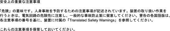
Use the thin, flat, RJ-45-to-RJ-45 rollover cable and RJ-45-to-DB-9 female DTE adapter (labeled TERMINAL) to connect the console port to a PC running terminal emulation software. Figure 1 shows how to connect the console port to a PC. Table 1 lists the pinouts for the asynchronous serial console port, the RJ-45-to-RJ-45 rollover cable, and the RJ-45-to-DB-9 female DTE adapter (labeled TERMINAL).
Figure 1 Connecting the Console Port to a PC
Table 1 Console Port Signaling and Cabling Using a DB-9 Adapter
Console
Port (DTE)
|
RJ-45-to-RJ-45
Rollover Cable
|
|
RJ-45-to-DB-9
Terminal Adapter (connected to Rollover Cable)
|
Console
Device
|
Signal
|
RJ-45 Pin
|
RJ-45 Pin
|
DB-9 Pin
|
Signal
|
RTS
|
11
|
8
|
8
|
CTS
|
DTR
|
2
|
7
|
6
|
DSR
|
TxD
|
3
|
6
|
2
|
RxD
|
GND
|
4
|
5
|
5
|
GND
|
GND
|
5
|
4
|
5
|
GND
|
RxD
|
6
|
3
|
3
|
TxD
|
DSR
|
7
|
2
|
4
|
DTR
|
CTS
|
81
|
1
|
7
|
RTS
|
Table 2 lists the pinouts for the asynchronous serial console port, the RJ-45-to-RJ-45 rollover cable, and the RJ-45-to-DB-25 female DTE adapter (labeled TERMINAL).
Table 2 Console Port Signaling and Cabling Using a DB-25 Adapter
Console
|
RJ-45-to-RJ-45
Rollover Cable
|
RJ-45-to-DB-25
Terminal Adapter
|
Console
Device
|
Signal
|
RJ-45 Pin
|
RJ-45 Pin
|
DB-25 Pin
|
Signal
|
RTS
|
12
|
8
|
5
|
CTS
|
DTR
|
2
|
7
|
6
|
DSR
|
TxD
|
3
|
6
|
3
|
RxD
|
GND
|
4
|
5
|
7
|
GND
|
GND
|
5
|
4
|
7
|
GND
|
RxD
|
6
|
3
|
2
|
TxD
|
DSR
|
7
|
2
|
20
|
DTR
|
CTS
|
82
|
1
|
4
|
RTS
|
Auxiliary Port Signals and Pinouts
Table 3 lists the pinouts for the asynchronous serial auxiliary port, the RJ-45-to-RJ-45 rollover cable, and the RJ-45-to-DB-25 male DCE adapter (labeled MODEM).
Table 3 Auxiliary Port Signaling and Cabling Using a DB-25 Adapter
Auxiliary
Port (DTE)
|
RJ-45-to-RJ-45
Roll-Over Cable
|
RJ-45-to-DB-25
Modem Adapter
|
Modem
|
Signal
|
RJ-45 Pin
|
RJ-45 Pin
|
DB-25 Pin
|
Signal
|
RTS
|
11
|
8
|
4
|
RTS
|
DTR
|
2
|
7
|
20
|
DTR
|
TxD
|
3
|
6
|
2
|
TxD
|
GND
|
4
|
5
|
7
|
GND
|
GND
|
5
|
4
|
7
|
GND
|
RxD
|
6
|
3
|
3
|
RxD
|
DSR
|
7
|
2
|
8
|
DCD
|
CTS
|
81
|
1
|
5
|
CTS
|
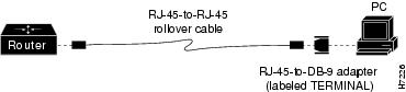
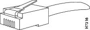
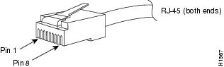
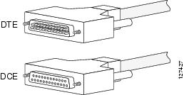
You can identify a rollover cable by comparing the modular plugs at the two ends of the cable. When you hold the plugs side by side, with the tab at the back, the wire connected to the pin on the outside of the left plug should be the same color as the wire connected to the pin on the outside of the right plug. (See Figure 2.) If you purchased your cable from Cisco Systems, pin 1 is white on one connector, and pin 8 is white on the other (a rollover cable connects pins 1 and 8, 2 and 7, 3 and 6, and 4 and 5).
Figure 2 Identifying a Rollover Cable
Ethernet Cable Pinouts
This section describes the following:
•Ethernet AUI Cable Pinouts
•10BASE-T Connector Pinouts
Ethernet AUI Cable Pinouts
Figure 3 shows the Ethernet (AUI) cable assembly, and Table 4 lists the pinouts.
Figure 3 Ethernet (AUI) Cable Assembly
Table 4 Ethernet (AUI) Pinouts
Pin
|
Ethernet Circuit
|
Signal Name
|
3
|
DO-A
|
Data Out Circuit A
|
10
|
DO-B
|
Data Out Circuit B
|
11
|
DO-S
|
Data Out Circuit Shield
|
5
|
DI-A
|
Data In Circuit A
|
12
|
DI-B
|
Data In Circuit B
|
4
|
DI-S
|
Data In Circuit Shield
|
7
|
CO-A
|
Control Out Circuit A (not connected)
|
15
|
CO-B
|
Control Out Circuit B (not connected)
|
8
|
CO-S
|
Control Out Circuit Shield (not connected)
|
2
|
CI-A
|
Control In Circuit A
|
9
|
CI-B
|
Control In Circuit B
|
1
|
CI-S
|
Control In Circuit Shield
|
6
|
VC
|
Voltage Common
|
13
|
VP
|
Voltage Plus
|
14
|
VS
|
Voltage Shield (L25 and M25)
|
Shell
|
PG
|
Protective Ground
|
10BASE-T Connector Pinouts
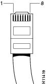
Figure 4 shows the 10BASE-T connector (RJ-45), and Table 5 lists its pinouts.
Figure 4 10BASE-T Connector (RJ-45)
Table 5 10BASE-T Connector (RJ-45) Pinouts
|
|
Description
|
1
|
TX+
|
2
|
TX-
|
3
|
RX+
|
4
|
—
|
5
|
—
|
6
|
RX-
|
7
|
—
|
8
|
—
|
Fast Ethernet Connector Pinouts
This section illustrates the Fast Ethernet 100BASE-TX (RJ-45) connector and lists its pinouts and signal descriptions.
Figure 5 shows the 100BASE-TX RJ-45 connector, and Table 6 lists its pinouts. The 1-port Fast Ethernet network module RJ-45 port actively terminates wire pair 4 and 5 and wire pair 7 and 8. Common-mode termination reduces electromagnetic interference (EMI) and susceptibility to common-mode sources.
Figure 5 100BaseTX RJ-45 Connector
Table 6 RJ-45 Connector Pinout
Pin
|
Signal
|
1
|
TX+
|
2
|
TX-
|
3
|
RX+
|
6
|
RX-
|
Token Ring Port Pinouts
The 1E1R 2-slot module provides both UTP and STP Token Ring connections described in these sections:
•Token Ring STP Connector Pinouts
•Token Ring UTP Connector Pinouts
The IEEE has established Token Ring as standard IEEE 802.5. The distance limitations for the IEEE 802.5 specification indicate a maximum segment distance of 328 feet (100 meters) for UTP cabling. The distance limitation is 1,640 feet (500 meters) for STP cabling.
Note To ensure agency compliance with FCC Class B electromagnetic emissions requirements (EMI), make sure that you use the shielded RJ-45 Token Ring cable when connecting your router to the Token Ring network.
Token Ring can operate at two different ring speeds: 4 and 16 Mbps. All devices on the ring must use the same operating speed.
Only one Token Ring port can be used at a time. The module will automatically detect which port, STP or UTP, is in use. Use the provided Token Ring cable to connect the router to a switch.
Token Ring STP Connector Pinouts
Table 7 shows the Token Ring STP port pinouts used by the 1E1R 2-slot module.
Table 7 Token Ring STP Port (DB-9) Pinouts
9-Pin
|
Signal Name
|
1
|
RX-
|
2
|
Ground
|
3
|
+5 Volt, fused
|
4
|
Ground
|
5
|
TX-
|
6
|
+RX
|
7
|
Ground
|
8
|
Ground
|
9
|
+TX
|
Token Ring UTP Connector Pinouts
Table 8 shows the Token Ring UTP port pinouts used by the 1E1R 2-slot module.
Table 8 Token Ring UTP Port (DB-9) Pinouts
RJ-45 Pins
|
Signal
|
1
|
GND
|
2
|
GND
|
3
|
TX
|
4
|
RX
|
5
|
TX
|
6
|
RX
|
7
|
GND
|
8
|
—
|
ISDN BRI Interface
This section contains the following topics:
•ISDN BRI Connections
•ISDN BRI Pinouts
Warning Network hazardous voltages are present in the BRI, fractional T1/T1, and switched 56 cables. If you detach the cable, detach the end away from the router first to avoid possible electric shock. Network hazardous voltages also are present on the system card in the area of the BRI port (RJ-45 connector), fractional T1/T1 port (RJ-48C connector), and switched port (RJ-11 or RJ-48S connector), regardless of when power is turned OFF. Statement 59
ISDN BRI Connections
Warning The ISDN connection is regarded as a source of voltage that should be inaccessible to user contact. Do not attempt to tamper with or open any public telephone operator (PTO)-provided equipment or connection hardware. Any hardwired connection (other than by a nonremovable, connect-one-time-only plug) must be made only by PTO staff or suitably trained engineers. Statement 23
Use a BRI cable (not included) to connect BRI ports on WAN interface cards (WICs) or on high speed WICs (HWICs) directly to an ISDN. Table 9 lists the specifications for ISDN BRI cables.
Table 9 ISDN BRI Cable Specifications
Specification
|
High-Capacitance Cable
|
Low-Capacitance Cable
|
Resistance (at 96 kHz)
|
160 ohms/km
|
160 ohms/km
|
Capacitance (at 1 kHz)
|
120 nF1 /km
|
30 nF/km
|
Impedance (at 96 kHz)
|
75 ohms
|
150 ohms
|
Wire diameter
|
0.024 in (0.6 mm)
|
0.024 in (0.6 mm)
|
Distance limitation
|
32.8 ft (10 m)
|
32.8 ft (10 m)
|
ISDN BRI Pinouts
Table 10 lists the connector signals and pinouts for an ISDN BRI S/T port. Table 11 lists the connector signals and pinouts for the ISDN BRI U port.
Caution To prevent damage to the system, make certain you connect the BRI cable to the BRI connector
only and not to any other RJ-45 connector.
Table 10 ISDN BRI S/T Port Signals and Pinouts (RJ-45)
|
|
|
|
Polarity
|
3
|
TX
|
RX
|
+
|
4
|
RX
|
TX
|
+
|
5
|
RX
|
TX
|
—
|
6
|
TX
|
RX
|
—
|
Table 11 ISDN BRI U Port Signals and Pinouts (RJ-45)
|
|
Function
|
3
|
No connection
|
4
|
Signal—Tip or Ring
|
5
|
Signal—Tip or Ring
|
6
|
No connection
|
CT1/PRI Pinouts
Two standard T1 serial cables are available for the CT1/PRI module: null modem and straight-through. A straight-through cable connects the router to an external CSU. Null modem cables are used for back-to-back operation and testing.
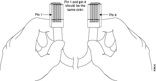
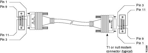
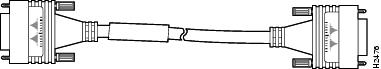
The T1 interface cable has two 15-pin DB connectors at each end to connect the CT1/PRI module with the external T1 CSU. Figure 6 shows the T1 interface cable, connectors, and pinouts. Table 12 lists the pinouts for the null modem T1 cable, and Table 13 lists the pinouts for the straight-through T1 cable.
Warning Network hazardous voltages are present in the BRI, fractional T1/T1, and switched 56 cables. If you detach the cable, detach the end away from the router first to avoid possible electric shock. Network hazardous voltages also are present on the system card in the area of the BRI port (RJ-45 connector), fractional T1/T1 port (RJ-48C connector), and switched port (RJ-11 or RJ-48S connector), regardless of when power is turned OFF. Statement 59
Figure 6 T1 Interface Cable
Table 12 Null Modem T1 Cable Pinouts
15-Pin DB Connector
|
|
|
15-Pin DB Connector
|
Signal
|
Pin
|
Pin
|
Signal
|
Transmit Tip
|
1
|
3
|
Receive Tip
|
Receive Tip
|
3
|
1
|
Transmit Tip
|
Transmit Ring
|
9
|
11
|
Receive Ring
|
Receive Ring
|
11
|
9
|
Transmit Ring
|
Table 13 Straight-Through T1 Cable Pinouts
15-Pin DB Connector
|
|
|
15-Pin DB Connector
|
Signal
|
Pin
|
Pin
|
Signal
|
Transmit Tip
|
1
|
1
|
Transmit Tip
|
Transmit Ring
|
9
|
9
|
Transmit Ring
|
Receive Tip
|
3
|
3
|
Receive Tip
|
Receive Ring
|
11
|
11
|
Receive Ring
|
CT1/PRI-CSU Pinouts
Table 14 lists the CT1/PRI-CSU module port pinouts. Use a straight-through RJ-48C-to-RJ-48C cable to connect the T1 port to an RJ-48C jack.
Table 14 CT1/PRI-CSU Module Port (RJ-48C) Pinouts
RJ-48C Pin
|
Description
|
1
|
Receive Ring
|
2
|
Receive Tip
|
4
|
Ring
|
5
|
Tip
|
CE1/PRI Interface
This section contains the following topics:
•CE1/PRI Cables
•CE1/PRI Pinouts
CE1/PRI Cables
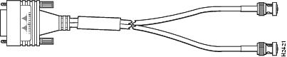
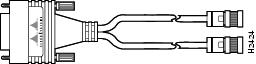
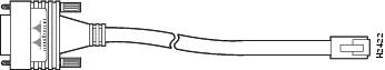
Cisco Systems makes four cables for the CE1/PRI modules. All four have DB-15 connectors on the CE1/PRI end and either BNC, DB-15, twinaxial, or RJ-45 connectors on the network end. Figure 7 through Figure 10 show the CE1/PRI interface cables.
Figure 7 E1 Interface Cable for 75-Ohm, Unbalanced Connections with BNC Connectors
Figure 8 E1 Interface Cable for 120-Ohm, Balanced Connections with DB-15 Connectors
Figure 9 E1 Interface Cable for 120-Ohm, Balanced Connections with Twinaxial Connectors
Figure 10 E1 Interface Cable for 120-Ohm, Balanced Connections with an RJ-45 Connector
CE1/PRI Pinouts
Table 15 lists pinouts for the CE1/PRI interface cables.
Table 15 E1 Interface Cable Pinouts
CE1/PRI End
|
Network End
|
DB-15
|
BNC
|
DB-15
|
Twinax
|
RJ-45
|
Pin
|
Signal
|
Signal
|
Pin
|
Signal
|
Pin
|
Signal
|
Pin
|
Signal
|
9
|
TX Tip
|
TX Tip
|
1
|
TX Tip
|
TX-1
|
TX Tip
|
1
|
TX Tip
|
2
|
TX Ring
|
TX Shield
|
9
|
TX Ring
|
TX-2
|
TX Ring
|
2
|
TX Ring
|
10
|
TX Shield
|
—
|
2
|
TX Shield
|
Shield
|
TX Shield
|
3
|
TX Shield
|
8
|
RX Tip
|
RX Tip
|
3
|
RX Tip
|
RX-1
|
RX Tip
|
4
|
RX Tip
|
15
|
RX Ring
|
RX Shield
|
11
|
RX Ring
|
RX-2
|
RX Ring
|
5
|
RX Ring
|
7
|
RX Shield
|
—
|
4
|
RX Shield
|
Shield
|
RX Shield
|
6
|
RX Shield
|
56/64-kbps DSU/CSU Signals and Pinouts
Switched 56-kbps connections are provided by the 56-kbps DSU/CSU WAN interface card (WIC). For more information, see the Network Modules Hardware Installation Guide.
Warning Network hazardous voltages are present in the BRI, fractional T1/T1, and switched 56 cables. If you detach the cable, detach the end away from the router first to avoid possible electric shock. Network hazardous voltages also are present on the system card in the area of the BRI port (RJ-45 connector), fractional T1/T1 port (RJ-48C connector), and switched port (RJ-11 or RJ-48S connector), regardless of when power is turned OFF. Statement 59
Table 16 lists the 56/64-kbps DSU/CSU connector signals and pinouts.
Table 16 56/64-Kbps DSU/CSU (RJ-48S) Signals and Pinouts
|
|
Description
|
1
|
Transmit Ring
|
2
|
Transmit Tip
|
7
|
Receive Tip
|
8
|
Receive Ring
|
T1/E1 Trunk and Digital Voice Port Pinouts (RJ-48)
Figure 11 shows the RJ-48 connector wiring for the T1/E1 trunk cable and the digital voice port cable; Table 17 lists the pinouts.
Figure 11 RJ-48-to-RJ-48 T1/E1 Cable Wiring
Table 17 Pinouts for T1/E1 Trunk and Digital Voice Port (RJ-48)
|
|
Signal
|
1
|
RX + (input)
|
2
|
RX - (input)
|
3
|
—
|
4
|
TX + (output)
|
5
|
TX - (output)
|
6
|
—
|
7
|
—
|
8
|
—
|
Analog Voice RJ-21 Pinouts
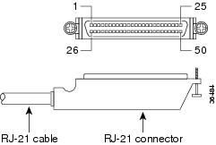
Figure 12 shows the RJ-21 connector wiring for the 50-pin Amphenol cable; Table 18 lists the pinouts.
Figure 12 RJ-21 Connector Wiring
Table 18 Pinouts for FXS and FXO Voice Ports
Pair
|
Ring Conductor
|
Tip Conductor
|
1
|
1
|
26
|
2
|
2
|
27
|
3
|
3
|
28
|
4
|
4
|
29
|
5
|
5
|
30
|
6
|
6
|
31
|
7
|
7
|
32
|
8
|
8
|
33
|
9
|
9
|
34
|
10
|
10
|
35
|
11
|
11
|
36
|
12
|
12
|
37
|
13
|
13
|
38
|
14
|
14
|
39
|
15
|
15
|
40
|
16
|
16
|
41
|
17
|
17
|
42
|
18
|
18
|
43
|
19
|
19
|
44
|
20
|
20
|
45
|
21
|
21
|
46
|
22
|
22
|
47
|
23
|
23
|
48
|
24
|
24
|
49
|
Serial Connection Signals and Pinouts
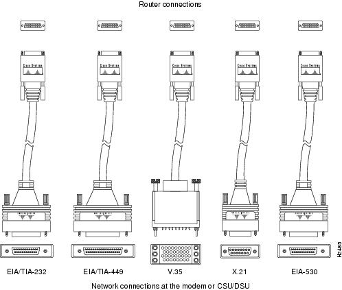
This section provides information about the 1-port serial WAN interface card (WIC). With the appropriate serial transition cable, this WIC can provide an EIA/TIA-232, EIA/TIA-449, V.35, X.21, DTE/DCE, EIA-530 DTE, or NRZ/NRZI serial interface.
Types of Serial Cables
Five types of serial cables (also called serial adapter cables or serial transition cables) are available from Cisco Systems:
•EIA/TIA-232 Interface
•EIA/TIA-449 Interface
•V.35 Interface
•X.21 Serial Cable Assembly
•EIA-530 Interface
All serial cables provide a universal plug at the WIC end. The network end of each cable provides the physical connectors most commonly used for the interface. For example, the network end of the EIA/TIA-232 serial cable is a DB-25 connector, the most widely used EIA/TIA-232 connector.
All serial interface types except EIA-530 are available in DTE or DCE format: DTE with a plug connector (male) at the network end and DCE with a receptacle (female) at the network end. V.35 is available in either mode with either gender at the network end. EIA-530 is available in DTE only.
Connecting the WIC to the Network
Note The serial WIC uses a universal high-density, 60-pin receptacle. Each universal port requires a serial port adapter cable that determines the port's electrical interface type and mode: DTE or DCE. Although all port adapter cables use a universal plug at the serial module end, the network end of each cable type uses the physical connectors commonly used for the interface. (For example, the network end of the EIA/TIA-232 port adapter cable is a DB-25 connector, the most widely used EIA/TIA-232 connector.)
After you install the serial WIC, use the appropriate serial cable to connect the WIC DB-60 serial port to one of the following types of equipment:
•An asynchronous modem, if connecting to an analog telephone line
•A synchronous modem, data service unit/channel service unit (DSU/CSU), or other data circuit-terminating equipment (DCE), if connecting to a digital WAN line
EIA/TIA-232 Interface
This section contains the following topics:
•EIA/TIA-232 Connections
•EIA/TIA-232 Serial Cable Assembly
EIA/TIA-232 Connections
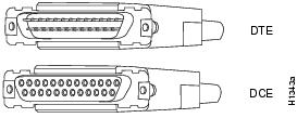
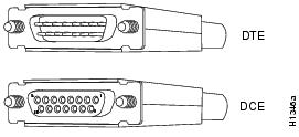
EIA/TIA-232 supports unbalanced circuits at signal speeds up to 64 kbps. The network end of the adapter cable is a standard 25-pin D-shell connector known as a DB-25. (See Figure 13.) The router console and auxiliary ports also use EIA/TIA-232 connections; however, the serial module ports support synchronous connections, and the console and auxiliary ports support asynchronous connections.
Figure 13 EIA/TIA-232 Adapter Cable Connectors, Network End
EIA/TIA-232 Serial Cable Assembly
Figure 14 shows the EIA/TIA-232 serial cable assembly. Table 19 lists the DTE pinout and Table 20 lists the DCE pinout. Arrows indicate signal direction: —> means DTE to DCE and <— means DCE to DTE.
Figure 14 EIA/TIA-232 Cable Assembly

Table 19 EIA/TIA-232 DTE Cable Pinout (DB-60 to DB-25)
60-Pin
|
Signal
|
Note
|
Direction
|
25-Pin
|
Signal
|
J1-50
J1-51
J1-52
|
MODE_0
GND
MODE_DCE
|
Shorting group
|
—
|
—
|
—
|
J1-46
|
Shield GND
|
Single
|
—
|
J2-1
|
Shield GND
|
J1-46
|
Shield GND
|
Single
|
—
|
J2-1
|
Shield GND
|
J1-41
Shield
|
TXD/RXD
—
|
Twisted pair no. 5
|
—>
—
|
J2-2
Shield
|
TXD
—
|
J1-36
Shield
|
RXD/TXD
—
|
Twisted pair no. 9
|
<—
—
|
J2-3
Shield
|
RXD
—
|
J1-42
Shield
|
RTS/CTS
—
|
Twisted pair no. 4
|
—>
—
|
J2-4
Shield
|
RTS
—
|
J1-35
Shield
|
CTS/RTS
—
|
Twisted pair no. 10
|
<—
—
|
J2-5
Shield
|
CTS
—
|
J1-34
Shield
|
DSR/DTR
—
|
Twisted pair no. 11
|
<—
—
|
J2-6
Shield
|
DSR
—
|
J1-45
Shield
|
Circuit GND
—
|
Twisted pair no. 1
|
—
—
|
J2-7
Shield
|
Circuit GND
—
|
J1-33
Shield
|
DCD/LL
—
|
Twisted pair no. 12
|
<—
—
|
J2-8
Shield
|
DCD
—
|
J1-37
Shield
|
TXC/NIL
—
|
Twisted pair no. 8
|
<—
—
|
J2-15
Shield
|
TXC
—
|
J1-38
Shield
|
RXC/TXCE
—
|
Twisted pair no. 7
|
<—
—
|
J2-17
Shield
|
RXC
—
|
J1-44
Shield
|
LL/DCD
—
|
Twisted pair no. 2
|
—>
—
|
J2-18
Shield
|
LTST
—
|
J1-43
Shield
|
DTR/DSR
—
|
Twisted pair no. 3
|
—>
—
|
J2-20
Shield
|
DTR
—
|
J1-39
Shield
|
TXCE/TXC
—
|
Twisted pair no. 6
|
—>
—
|
J2-24
Shield
|
TXCE
—
|
Table 20 EIA/TIA-232 DCE Cable Pinout (DB-60 to DB-25)
60-Pin
|
Signal
|
Note
|
Direction
|
25-Pin
|
Signal
|
J1-50
J1-51
|
MODE_0
GND
|
Shorting group
|
—
|
—
|
—
|
J1-36
Shield
|
RXD/TXD
—
|
Twisted pair no. 9
|
<—
—
|
J2-2
Shield
|
TXD
—
|
J1-41
Shield
|
TXD/RXD
—
|
Twisted pair no. 5
|
—>
—
|
J2-3
Shield
|
RXD
—
|
J1-35
Shield
|
CTS/RTS
—
|
Twisted pair no. 10
|
<—
—
|
J2-4
Shield
|
RTS
—
|
J1-42
Shield
|
RTS/CTS
—
|
Twisted pair no. 4
|
—>
—
|
J2-5
Shield
|
CTS
—
|
J1-43
Shield
|
DTR/DSR
—
|
Twisted pair no. 3
|
—>
—
|
J2-6
Shield
|
DSR
—
|
J1-45
Shield
|
Circuit GND
—
|
Twisted pair no. 1
|
—
—
|
J2-7
Shield
|
Circuit GND
|
J1-44
Shield
|
LL/DCD
—
|
Twisted pair no. 2
|
—>
—
|
J2-8
Shield
|
DCD
—
|
J1-39
Shield
|
TXCE/TXC
—
|
Twisted pair no. 7
|
—>
—
|
J2-15
Shield
|
TXC
—
|
J1-40
Shield
|
NIL/RXC
—
|
Twisted pair no. 6
|
—>
—
|
J2-17
Shield
|
RXC
—
|
J1-33
Shield
|
DCD/LL
—
|
Twisted pair no. 12
|
<—
—
|
J2-18
Shield
|
LTST
—
|
J1-34
Shield
|
DSR/DTR
—
|
Twisted pair no. 11
|
<—
—
|
J2-20
Shield
|
DTR
—
|
J1-38
Shield
|
RXC/TXCE
—
|
Twisted pair no. 8
|
<—
—
|
J2-24
Shield
|
TXCE
—
|
EIA/TIA-449 Interface
This section contains the following topics:
•EIA/TIA-449 Connections
•EIA/TIA-449 Serial Cable Assembly
EIA/TIA-449 Connections
EIA/TIA-449, which supports balanced (EIA/TIA-422) and unbalanced (EIA/TIA-423) transmissions, is a faster (up to 2 Mbps) version of EIA/TIA-232 that provides more functions and supports transmissions over greater distances.
The EIA/TIA-449 standard was intended to replace the EIA/TIA-232 standard, but it was not widely adopted primarily because of the large installed base of DB-25 hardware and because of the larger size of the 37-pin EIA/TIA-449 connectors, which limited the number of connections possible (fewer than possible with the smaller, 25-pin EIA/TIA-232 connector).
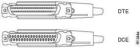
The network end of the EIA/TIA-449 adapter cable provides a standard 37-pin D-shell connector. (See Figure 15.) EIA/TIA-449 cables are available as either DTE (DB-37 plug) or DCE (DB-37 receptacle).
Figure 15 EIA/TIA-449 Adapter Cable Connectors, Network End
EIA/TIA-449 Serial Cable Assembly
Figure 16 shows the EIA/TIA-449 serial cable assembly. Table 21 lists the DTE pinout, and Table 22 lists the DCE pinout. Arrows indicate signal direction: —> means DTE to DCE and <— means DCE to DTE.
Figure 16 EIA/TIA-449 Serial Cable Assembly
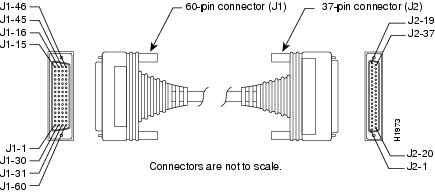
Table 21 EIA/TIA-449 DTE Cable Pinout (DB-60 to DB-37)
60-Pin
|
Signal Name
|
Note
|
Direction
|
37-Pin
|
Signal Name
|
J1-49
J1-48
|
MODE_1
GND
|
Shorting group
|
—
|
—
|
—
|
J1-51
J1-52
|
GND
MODE_DCE
|
Shorting group
|
—
|
—
|
—
|
J1-46
|
Shield_GND
|
Single
|
_
|
J2-1
|
Shield GND
|
J1-11
J1-12
|
TXD/RXD+
TXD/RXD-
|
Twisted pair no. 6
|
—>
—>
|
J2-4
J2-22
|
SD+
SD-
|
J1-24
J1-23
|
TXC/RXC+
TXC/RXC-
|
Twisted pair no. 9
|
<—
<—
|
J2-5
J2-23
|
ST+
ST-
|
J1-28
J1-27
|
RXD/TXD+
RXD/TXD-
|
Twisted pair no. 11
|
<—
<—
|
J2-6
J2-24
|
RD+
RD-
|
J1-9
J1-10
|
RTS/CTS+
RTS/CTS-
|
Twisted pair no. 5
|
—>
—>
|
J2-7
J2-25
|
RS+
RS-
|
J1-26
J1-25
|
RXC/TXCE+
RXC/TXCE-
|
Twisted pair no. 10
|
<—
<—
|
J2-8
J2-26
|
RT+
RT-
|
J1-1
J1-2
|
CTS/RTS+
CTS/RTS-
|
Twisted pair no. 1
|
<—
<—
|
J2-9
J2-27
|
CS+
CS-
|
J1-44
J1-45
|
LL/DCD
Circuit_GND
|
Twisted pair no. 12
|
—>
—
|
J2-10
J2-37
|
LL
SC
|
J1-3
J1-4
|
DSR/DTR+
DSR/DTR-
|
Twisted pair no. 2
|
<—
<—
|
J2-11
J2-29
|
DM+
DM-
|
J1-7
J1-8
|
DTR/DSR+
DTR/DSR-
|
Twisted pair no. 4
|
—>
—>
|
J2-12
J2-30
|
TR+
TR-
|
J1-5
J1-6
|
DCD/DCD+
DCD/DCD-
|
Twisted pair no. 3
|
<—
<—
|
J2-13
J2-31
|
RR+
RR-
|
J1-13
J1-14
|
TXCE/TXC+
TXCE/TXC-
|
Twisted pair no. 7
|
—>
—>
|
J2-17
J2-35
|
TT+
TT-
|
J1-15
J1-16
|
Circuit_GND
Circuit_GND
|
Twisted pair no. 9
|
—
—
|
J2-19
J2-20
|
SG
RC
|
Table 22 EIA/TIA-449 DCE Cable Pinout (DB-60 to DB-37)
60-Pin
|
Signal Name
|
Note
|
Direction
|
37-Pin
|
Signal Name
|
J1-49
J1-48
|
MODE_1
GND
|
Shorting group
|
—
|
—
|
—
|
J1-46
|
Shield_GND
|
Single
|
—
|
J2-1
|
Shield GND
|
J1-28
J1-27
|
RXD/TXD+
RXD/TXD-
|
Twisted pair no. 11
|
<—
<—
|
J2-4
J2-22
|
SD+
SD-
|
J1-13
J1-14
|
TXCE/TXC+
TXCE/TXC-
|
Twisted pair no. 7
|
—>
—>
|
J2-5
J2-23
|
ST+
ST-
|
J1-11
J1-12
|
TXD/RXD+
TXD/RXD-
|
Twisted pair no. 6
|
—>
—>
|
J2-6
J2-24
|
RD+
RD-
|
J1-1
J1-2
|
CTS/RTS+
CTS/RTS-
|
Twisted pair no. 1
|
<—
<—
|
J2-7
J2-25
|
RS+
RS-
|
J1-24
J1-23
|
TXC/RXC+
TXC/RXC-
|
Twisted pair no. 9
|
—>
—>
|
J2-8
J2-26
|
RT+
RT-
|
J1-9
J1-10
|
RTS/CTS+
RTS/CTS-
|
Twisted pair no. 5
|
—>
—>
|
J2-9
J2-27
|
CS+
CS-
|
J1-29
J1-30
|
NIL/LL
Circuit_GND
|
Twisted pair no. 12
|
—>
—
|
J2-10
J2-37
|
LL
SC
|
J1-7
J1-8
|
DTR/DSR+
DTR/DSR-
|
Twisted pair no. 4
|
—>
—>
|
J2-11
J2-29
|
DM+
DM-
|
J1-3
J1-4
|
DSR/DTR+
DSR/DTR-
|
Twisted pair no. 2
|
<—
<—
|
J2-12
J2-30
|
TR+
TR-
|
J1-5
J1-6
|
DCD/DCD+
DCD/DCD-
|
Twisted pair no. 3
|
—>
—>
|
J2-13
J2-31
|
RR+
RR-
|
J1-26
J1-25
|
RXC/TXCE+
RXC/TXCE-
|
Twisted pair no. 10
|
<—
<—
|
J2-17
J2-35
|
TT+
TT-
|
J1-15
J1-16
|
Circuit_GND
Circuit_GND
|
Twisted pair no. 8
|
—
—
|
J2-19
J2-20
|
SG
RC
|
V.35 Interface
This section contains the following topics:
•V.35 Connections
•V.35 Serial Cable Assembly
V.35 Connections
The V.35 interface is recommended for speeds up to 48 kbps, although in practice it is used successfully at 4 Mbps.
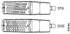
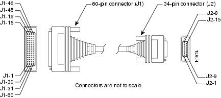
The network end of the V.35 adapter cable provides a standard 34-pin Winchester-type connector. (See Figure 17.) V.35 cables are available with a standard V.35 plug or receptacle in either DTE or DCE mode.
Figure 17 V.35 Adapter Cable Connectors, Network End
V.35 Serial Cable Assembly
Figure 18 shows the V.35 serial cable assembly. Table 23 lists the DTE pinout and Table 24 lists the DCE pinout. Arrows indicate signal direction: —> means DTE to DCE and <— means DCE to DTE.
Figure 18 V.35 Serial Cable Assembly
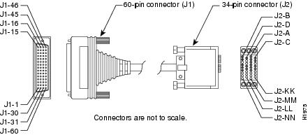
Table 23 V.35 DTE Cable Pinout (DB-60 to Winchester-Type 34-Pin)
60-Pin
|
Signal Name
|
Type
|
Direction
|
34-Pin
|
Signal Name
|
J1-49
J1-48
|
MODE_1
GND
|
Shorting group
|
—
|
—
|
—
|
J1-50
J1-51
J1-52
|
MODE_0
GND
MODE_DCE
|
Shorting group
|
—
|
—
|
—
|
J1-53
J1-54
J1-55
J1-56
|
TxC/NIL
RxC_TxCE
RxD/TxD
GND
|
Shorting group
|
—
|
—
|
—
|
J1-46
|
Shield_GND
|
Single
|
—
|
J2-A
|
Frame GND
|
J1-45
Shield
|
Circuit_GND
—
|
Twisted pair no. 12
|
—
—
|
J2-B
Shield
|
Circuit GND
—
|
J1-42
Shield
|
RTS/CTS
—
|
Twisted pair no. 9
|
—>
—
|
J2-C
Shield
|
RTS
—
|
J1-35
Shield
|
CTS/RTS
—
|
Twisted pair no. 8
|
<—
—
|
J2-D
Shield
|
CTS
—
|
J1-34
Shield
|
DSR/DTR
—
|
Twisted pair no. 7
|
<—
—
|
J2-E
Shield
|
DSR
—
|
J1-33
Shield
|
DCD/LL
—
|
Twisted pair no. 6
|
<—
—
|
J2-F
Shield
|
RLSD
—
|
J1-43
Shield
|
DTR/DSR
—
|
Twisted pair no. 10
|
—>
—
|
J2-H
Shield
|
DTR
—
|
J1-44
Shield
|
LL/DCD
—
|
Twisted pair no. 11
|
—>
—
|
J2-K
Shield
|
LT
—
|
J1-18
J1-17
|
TxD/RxD+
TxD/RxD-
|
Twisted pair no. 1
|
—>
—>
|
J2-P
J2-S
|
SD+
SD-
|
J1-28
J1-27
|
RxD/TxD+
RxD/TxD-
|
Twisted pair no. 5
|
<—
<—
|
J2-R
J2-T
|
RD+
RD-
|
J1-20
J1-19
|
TxCE/TxC+
TxCE/TxC-
|
Twisted pair no. 2
|
—>
—>
|
J2-U
J2-W
|
SCTE+
SCTE-
|
J1-26
J1-25
|
RxC/TxCE+
RxC/TxCE-
|
Twisted pair no. 4
|
<—
<—
|
J2-V
J2-X
|
SCR+
SCR-
|
J1-24
J1-23
|
TxC/RxC+
TxC/RxC-
|
Twisted pair no. 3
|
<—
<—
|
J2-Y
J2-AA
|
SCT+
SCT-
|
Table 24 V.35 DCE Cable Pinout (DB-60 to Winchester-Type 34-Pin)
60-Pin
|
Signal Name
|
Type
|
Direction
|
34-Pin
|
Signal Name
|
J1-49
J1-48
|
MODE_1
GND
|
Shorting group
|
—
|
—
|
—
|
J1-50
J1-51
|
MODE_0
GND
|
Shorting group
|
—
|
—
|
—
|
J1-53
J1-54
J1-55
J1-56
|
TxC/NIL
RxC_TxCE
RxD/TxD
GND
|
Shorting group
|
—
|
—
|
—
|
J1-46
|
Shield_GND
|
Single
|
—
|
J2-A
|
Frame GND
|
J1-45
Shield
|
Circuit_GND
—
|
Twisted pair no. 12
|
—
—
|
J2-B
Shield
|
Circuit GND
—
|
J1-35
Shield
|
CTS/RTS
—
|
Twisted pair no. 8
|
<—
—
|
J2-C
Shield
|
RTS
—
|
J1-42
Shield
|
RTS/CTS
—
|
Twisted pair no. 9
|
—>
—
|
J2-D
Shield
|
CTS
—
|
J1-43
Shield
|
DTR/DSR
—
|
Twisted pair no. 10
|
—>
—
|
J2-E
Shield
|
DSR
—
|
J1-44
Shield
|
LL/DCD
—
|
Twisted pair no. 11
|
—>
—
|
J2-F
Shield
|
RLSD
—
|
J1-34
Shield
|
DSR/DTR
—
|
Twisted pair no. 7
|
<—
—
|
J2-H
Shield
|
DTR
—
|
J1-33
Shield
|
DCD/LL
—
|
Twisted pair no. 6
|
<—
—
|
J2-K
Shield
|
LT
—
|
J1-28
J1-27
|
RxD/TxD+
RxD/TxD-
|
Twisted pair no. 5
|
<—
<—
|
J2-P
J2-S
|
SD+
SD-
|
J1-18
J1-17
|
TxD/RxD+
TxD/RxD-
|
Twisted pair no. 1
|
—>
—>
|
J2-R
J2-T
|
RD+
RD-
|
J1-26
J1-25
|
RxC/TxCE+
RxC/TxCE-
|
Twisted pair no. 4
|
<—
<—
|
J2-U
J2-W
|
SCTE+
SCTE-
|
J1-22
J1-21
|
NIL/RxC+
NIL/RxC-
|
Twisted pair no. 3
|
—>
—>
|
J2-V
J2-X
|
SCR+
SCR-
|
J1-20
J1-19
|
TxCE/TxC+
TxCE/TxC-
|
Twisted pair no. 2
|
—>
—>
|
J2-Y
J2-AA
|
SCT+
SCT-
|
X.21 Interface
This section contains the following topics:
•X.21 Connections
•X.21 Serial Cable Assembly
X.21 Connections
The X.21 interface uses a 15-pin connection for balanced circuits and is commonly used in the United Kingdom to connect public data networks. X.21 relocates some of the logic functions to the DTE and DCE interfaces and, as a result, requires fewer circuits and a smaller connector than EIA/TIA-232.
The network end of the X.21 adapter cable is a standard DB-15 connector. (See Figure 19.) X.21 cables are available as either DTE (DB-15 plug) or DCE (DB-15 receptacle).
Figure 19 X.21 Adapter Cable Connectors, Network End
X.21 Serial Cable Assembly
Figure 20 shows the X.21 serial cable assembly. Table 25 lists the DTE pinout, and Table 26 lists the DCE pinout. Arrows indicate signal direction: —> means DTE to DCE and <— means DCE to DTE.
Figure 20 X.21 Serial Cable Assembly
Table 25 X.21 DTE Cable Pinout (DB-60 to DB-15)
60-Pin
|
Signal Name
|
Type
|
Direction
|
15-Pin
|
Signal Name
|
J1-48
J1-47
|
GND
MODE_2
|
Shorting group
|
—
|
—
|
—
|
J1-51
J1-52
|
GND
MODE_DCE
|
Shorting group
|
—
|
—
|
—
|
J1-46
|
Shield_GND
|
Single
|
—
|
J2-1
|
Shield GND
|
J1-11
J1-12
|
TXD/RXD+
TXD/RXD-
|
Twisted pair no. 3
|
—>
—>
|
J2-2
J2-9
|
Transmit+
Transmit-
|
J1-9
J1-10
|
RTS/CTS+
RTS/CTS-
|
Twisted pair no. 2
|
—>
—>
|
J2-3
J2-10
|
Control+
Control-
|
J1-28
J1-27
|
RXD/TXD+
RXD/TXD-
|
Twisted pair no. 6
|
<—
<—
|
J2-4
J2-11
|
Receive+
Receive-
|
J1-1
J1-2
|
CTS/RTS+
CTS/RTS-
|
Twisted pair no. 1
|
<—
<—
|
J2-5
J2-12
|
Indication+
Indication-
|
J1-26
J1-25
|
RXC/TXCE+
RXC/TXCE-
|
Twisted pair no. 5
|
<—
<—
|
J2-6
J2-13
|
Timing+
Timing-
|
J1-15
Shield
|
Control_GND
—
|
Twisted pair no. 4
|
—
—
|
J2-8
Shield
|
Control GND
—
|
Table 26 X.21 Serial DCE Cable Pinout (DB-60 to DB-15)
60-Pin
|
Signal Name
|
Type
|
Direction
|
15-Pin
|
Signal Name
|
J1-48
J1-47
|
GND
MODE_2
|
Shorting group
|
—
|
—
|
—
|
J1-46
|
Shield_GND
|
Single
|
—
|
J2-1
|
Shield GND
|
J1-28
J1-27
|
RXD/TXD+
RXD/TXD-
|
Twisted pair no. 6
|
<—
<—
|
J2-2
J2-9
|
Transmit+
Transmit-
|
J1-1
J1-2
|
CTS/RTS+
CTS/RTS-
|
Twisted pair no. 1
|
<—
<—
|
J2-3
J2-10
|
Control+
Control-
|
J1-11
J1-12
|
TXD/RXD+
TXD/RXD-
|
Twisted pair no. 3
|
—>
—>
|
J2-4
J2-11
|
Receive+
Receive-
|
J1-9
J1-10
|
RTS/CTS+
RTS/CTS-
|
Twisted pair no. 2
|
—>
—>
|
J2-5
J2-12
|
Indication+
Indication-
|
J1-24
J1-23
|
TXC/RXC+
TXC/RXC-
|
Twisted pair no. 4
|
—>
—>
|
J2-6
J2-13
|
Timing+
Timing-
|
J1-15
Shield
|
Control_GND
—
|
Twisted pair no. 5
|
—
—
|
J2-8
Shield
|
Control GND
—
|
EIA-530 Interface
This section contains the following topics:
•EIA-530 Connections
•EIA-530 Serial Cable Assembly
EIA-530 Connections
EIA-530, which supports balanced transmission, provides the increased functionality, speed, and distance of EIA/TIA-449 on the smaller DB-25 connector used for EIA/TIA-232, instead of the 37-pin connectors used for EIA/TIA-449. Like EIA/TIA-449, EIA-530 refers to the electrical specifications of EIA/TIA-422 and EIA/TIA-423. Although the specification recommends a maximum speed of 2 Mbps, EIA-530 is used successfully at 4 Mbps or faster speeds over short distances.
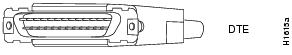
The EIA-530 adapter cable is available in DTE mode only. The network end of the EIA-530 adapter cable is a standard DB-25 plug commonly used for EIA/TIA-232 connections. Figure 21 shows the DB-25 connector at the network end of the adapter cable.
Figure 21 EIA-530 Adapter Cable Connector, Network End
EIA-530 Serial Cable Assembly
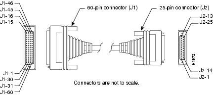
Figure 22 shows the EIA-530 serial cable assembly, and Table 27 lists the pinout. Arrows indicate signal direction: —> means DTE to DCE and <— means DCE to DTE.
The EIA-530 interface cannot be operated in DCE mode, and no DCE cable is available for it.
Figure 22 EIA-530 Serial Cable Assembly
Table 27 EIA-530 DTE Cable Pinout (DB-60 to DB-25)
60-Pin
|
Signal Name
|
25-Pin
|
Signal Name
|
Direction
|
J1-11
J1-12
|
TXD/RXD+
TXD/RXD-
|
J2-2
J2-14
|
BA(A), TXD+
BA(B), TXD-
|
—>
—>
|
J1-28
J1-27
|
RXD/TXD+
RXD/TXD-
|
J2-3
J2-16
|
BB(A), RXD+
BB(B), RXD-
|
<—
<—
|
J1-9
J1-10
|
RTS/CTS+
RTS/CTS-
|
J2-4
J2-19
|
CA(A), RTS+
CA(B), RTS-
|
—>
—>
|
J1-1
J1-2
|
CTS/RTS+
CTS/RTS-
|
J2-5
J2-13
|
CB(A), CTS+
CB(B), CTS-
|
<—
<—
|
J1-3
J1-4
|
DSR/DTR+
DSR/DTR-
|
J2-6
J2-22
|
CC(A), DSR+
CC(B), DSR-
|
<—
<—
|
J1-46
J1-47
|
Shield_GND
MODE_2
|
J2-1
—
|
Shield
—
|
Shorted
|
J1-48
J1-49
|
GND
MODE_1
|
—
—
|
—
—
|
Shorted
|
J1-5
J1-6
|
DCD/DCD+
DCD/DCD-
|
J2-8
J2-10
|
CF(A), DCD+
CF(B), DCD-
|
<—
<—
|
J1-24
J1-23
|
TXC/RXC+
TXC/RXC-
|
J2-15
J2-12
|
DB(A), TXC+
DB(B), TXC-
|
<—
<—
|
J1-26
J1-25
|
RXC/TXCE+
RXC/TXCE-
|
J2-17
J2-9
|
DD(A), RXC+
DD(B), RXC-
|
<—
<—
|
J1-44
J1-45
|
LL/DCD
Circuit_GND
|
J2-18
J2-7
|
LL
Circuit_ GND
|
—>
—
|
J1-7
J1-8
|
DTR/DSR+
DTR/DSR-
|
J2-20
J2-23
|
CD(A), DTR+
CD(B), DTR-
|
—>
—>
|
J1-13
J1-14
|
TXCE/TXC+
TXCE/TXC-
|
J2-24
J2-11
|
DA(A), TXCE+
DA(B), TXCE-
|
—>
—>
|
J1-51
J1-52
|
GND
MODE_DCE
|
—
—
|
—
—
|
Shorted
|
Smart Serial Connection Signals and Pinouts
The Smart Serial cable interface supports multiple independent serial interface ports. Each port supports five types of serial interfaces:
•EIA/TIA-232 Smart Serial Cable Assembly
•EIA/TIA-449 Smart Serial Cable Assembly
•X.21 Smart Serial Cable Assembly
•V.35 Smart Serial Cable Assembly
•EIA-530 Smart Serial Cable Assembly
The serial end (router end) of the Smart Serial cable is a 26-pin connector.
These cables are used with the following interface cards:
•2-port serial and 2-port asynchronous or synchronous WICs
•4-port serial and 4-port asynchronous or synchronous high-speed WICs (HWICs)
Figure 23 shows the serial cables you can connect to the port on the asynchronous or synchronous serial modules and the serial WICs and HWICs.
Figure 23 Smart Serial Interface Cables
EIA/TIA-232 Smart Serial Cable Assembly
Table 28 lists the DTE pinout, and Table 29 lists the DCE pinout for the EIA/TIA-232 Smart Serial cable. Arrows indicate signal direction: —> means DTE to DCE and <— means DCE to DTE.
Table 28 EIA/TIA-232 DTE Smart Serial Cable Pinout
26-Pin
|
Signal Name
|
Note
|
Direction
|
DB-25 Pin
|
Signal Name
|
J1-23
J1-24
|
MODE_0
MODE_DCE
|
Local connections
|
|
|
|
Drain wire
|
|
Shield
|
—
|
J2-01
|
Shield_GND
|
J1-05
J1-18
|
I_RXD/TXD+
GND+
|
Twisted pair no. 9
|
<—
—
|
J2-03
|
RXD
GND
|
J1-01
J1-14
|
O_TXD/RXD+
GND+
|
Twisted pair no. 5
|
—>
—
|
J2-02
|
TXD
GND
|
J1-11
J1-12
|
I_CTS/RTS+
I_DSR/DTR+
|
Twisted pair no. 2
|
<—
<—
|
J2-05
J2-06
|
CTS
DSR
|
J1-08
J1-07
|
O_RTS/CTS
O_DTR/DSR+
|
Twisted pair no. 4
|
—>
—>
|
J2-04
J2-20
|
RTS
DTR
|
J1-06
J1-19
|
B_DCD/DCD+
GND+
|
Twisted pair no. 1
|
<—
—
|
J2-08
J2-07
|
DCD
GND
|
J1-03
J1-16
|
B_TXC/TXC+
GND+
|
Twisted pair no. 7
|
<—
—
|
J2-15
|
TXC
GND
|
J1-02
J1-15
|
O_TXCE/RXC+
GND+
|
Twisted pair no. 6
|
—>
—
|
J2-24
|
TXCE
GND
|
J1-13
J1-26
|
B_LL/LL+
GND+
|
Twisted pair no. 3
|
—>
—
|
J2-18
|
LTST
GND
|
J1-04
J1-17
|
I_RXC/TXCE+
GND+
|
Twisted pair no. 8
|
<—
—
|
J2-17
|
RXC
GND
|
Table 29 EIA/TIA-232 DCE Smart Serial Cable Pinout
26-Pin
|
Signal Name
|
Note
|
Direction
|
DB-25 Pin
|
Signal Name
|
J1-23
|
MODE_0
|
Local connections
|
|
|
|
Drain wire
|
|
Shield
|
—
|
J2-01
|
Shield_GND
|
J1-05
J1-18
|
I_RXD/TXD+
GND+
|
Twisted pair no. 5
|
<—
—
|
J2-02
|
TXD
GND
|
J1-01
J1-14
|
O_TXD/RXD+
GND+
|
Twisted pair no. 9
|
—>
—
|
J2-03
|
RXD
GND
|
J1-11
J1-12
|
I_CTS/RTS+
I_DSR/DTR+
|
Twisted pair no. 2
|
<—
<—
|
J2-04
J2-20
|
RTS
DTR
|
J1-08
J1-07
|
O_RTS/CTS
O_DTR/DSR+
|
Twisted pair no. 4
|
—>
—>
|
J2-05
J2-06
|
CTS
DSR
|
J1-06
J1-19
|
B_DCD/DCD+
GND+
|
Twisted pair no. 1
|
—>
—
|
J2-08
J2-07
|
DCD
GND
|
J1-03
J1-16
|
B_TXC/TXC+
GND+
|
Twisted pair no. 7
|
—>
—
|
J2-15
|
TXC
GND
|
J1-02
J1-15
|
O_TXCE/RXC+
GND+
|
Twisted pair no. 8
|
—>
—
|
J2-17
|
RXC
GND
|
J1-13
J1-26
|
B_LL/LL+
GND+
|
Twisted pair no. 3
|
<—
—
|
J2-18
|
LTST
GND
|
J1-04
J1-17
|
I_RXC/TXCE+
GND+
|
Twisted pair no. 6
|
<—
—
|
J2-24
|
TXCE
GND
|
EIA/TIA-449 Smart Serial Cable Assembly
Table 30 lists the DTE pinout, and Table 31 lists the DCE pinout for the EIA/TIA-449 Smart Serial cable. Arrows indicate signal direction: —> means DTE to DCE and <— means DCE to DTE.
Table 30 EIA/TIA-449 DTE Smart Serial Cable Pinout
26-Pin
|
Signal Name
|
Note
|
Direction
|
DB-37 Pin
|
Signal Name
|
Drain wire
|
|
Shield
|
—
|
J2-01
|
Shield_GND
|
J1-22
J1-24
|
MODE_I
MODE_DCE
|
Twisted pair no. 2
|
—
—
|
J2-19
J2-20
|
SG
RC
|
J1-01
J1-14
|
O_TXD/RXD+
O_TXD/RXD-
|
Twisted pair no. 5
|
—>
—>
|
J2-04
J2-22
|
SD+
SD-
|
J1-03
J1-16
|
B_TXC/TXC+
B_TXC/TXC-
|
Twisted pair no. 7
|
<—
<—
|
J2-05
J2-23
|
ST+
ST-
|
J1-05
J1-18
|
I_RXD/TXD+
I_RXD/TXD-
|
Twisted pair no. 9
|
<—
<—
|
J2-06
J2-24
|
RD+
RD-
|
J1-08
J1-09
|
O_RTS/CTS
O_RTS/CTS-
|
Twisted pair no. 1
|
—>
—>
|
J2-07
J2-25
|
RS+
RS-
|
J1-04
J1-17
|
I_RXC/TXCE+
I_RXC/TXCE-
|
Twisted pair no. 8
|
<—
<—
|
J2-08
J2-26
|
RT+
RT-
|
J1-11
J1-10
|
I_CTS/RTS+
I_CTS/RTS-
|
Twisted pair no. 4
|
<—
<—
|
J2-09
J2-27
|
CS+
CS-
|
J1-13
J1-26
|
B_LL/LL+
GND+
|
Twisted pair no. 12
|
—>
—
|
J2-10
J2-37
|
LL
SC
|
J1-12
J1-25
|
I_DTR/DSR+
I_DTR/DSR-
|
Twisted pair no. 10
|
<—
<—
|
J2-11
J2-29
|
DM+
DM-
|
J1-07
J1-20
|
O_DTR/DSR+
O_DTR/DSR-
|
Twisted pair no. 3
|
—>
—>
|
J2-12
J2-30
|
TR+
TR-
|
J1-02
J1-15
|
O_TXCE/RXC+
O_TXCE/RXC-
|
Twisted pair no. 6
|
—>
—>
|
J2-17
J2-35
|
TT+
TT-
|
J1-06
J1-19
|
B_DCD/DCD+
B_DCD/DCD-
|
Twisted pair no. 11
|
<—
<—
|
J2-13
J2-31
|
RR+
RR-
|
Table 31 EIA/TIA-449 DCE Smart Serial Cable Pinout
26-Pin
|
Signal Name
|
Note
|
Direction
|
DB-37 Pin
|
Signal Name
|
Drain wire
|
|
Shield
|
—
|
J2-01
|
Shield_GND
|
J1-22
|
MODE_I
Not used
|
Twisted pair no. 2
|
—
|
J2-19
J2-20
|
SG
RC
|
J1-05
J1-18
|
I_RXD/TXD+
I_RXD/TXD-
|
Twisted pair no. 5
|
<—
<—
|
J2-04
J2-22
|
SD+
SD-
|
J1-03
J1-16
|
B_TXC/TXC+
B_TXC/TXC-
|
Twisted pair no. 7
|
—>
—>
|
J2-05
J2-23
|
ST+
ST-
|
J1-01
J1-14
|
O_TXD/RXD+
O_TXD/RXD-
|
Twisted pair no. 9
|
—>
—>
|
J2-06
J2-24
|
RD+
RD-
|
J1-11
J1-10
|
I_CTS/RTS+
I_CTS/RTS-
|
Twisted pair no. 1
|
<—
<—
|
J2-07
J2-25
|
RS+
RS-
|
J1-02
J1-15
|
O_TXCE/RXC+
O_TXCE/RXC-
|
Twisted pair no. 8
|
—>
—>
|
J2-08
J2-26
|
RT+
RT-
|
J1-08
J1-09
|
O_RTS/CTS
O_RTS/CTS-
|
Twisted pair no. 4
|
—>
—>
|
J2-09
J2-27
|
CS+
CS-
|
J1-06
J1-19
|
B_DCD/DCD+
B_DCD/DCD-
|
Twisted pair no. 11
|
—>
—>
|
J2-13
J2-31
|
RR+
RR-
|
J1-07
J1-20
|
O_DTR/DSR+
O_DTR/DSR-
|
Twisted pair no. 10
|
—>
—>
|
J2-11
J2-29
|
DM+
DM-
|
J1-12
J1-25
|
I_DTR/DSR+
I_DTR/DSR-
|
Twisted pair no. 3
|
<—
<—
|
J2-12
J2-30
|
TR+
TR-
|
J1-13
J1-26
|
B_LL/LL+
GND+
|
Twisted pair no. 12
|
—>
—
|
J2-10
J2-37
|
LL
SC
|
J1-04
J1-17
|
I_RXC/TXCE+
I_RXC/TXCE-
|
Twisted pair no. 6
|
<—
<—
|
J2-17
J2-35
|
TT+
TT-
|
X.21 Smart Serial Cable Assembly
Table 32 lists the DTE pinout, and Table 33 lists the DCE pinout for the X.21 Smart Serial cable. Arrows indicate signal direction: —> means DTE to DCE and <— means DCE to DTE.
Table 32 X.21 DTE Smart Serial Cable Pinout
26-Pin
|
Signal Name
|
Note
|
Direction
|
DB-15 Pin
|
Signal Name
|
J1-21
J1-24
|
MODE_2
MODE_DCE
|
Local connections
|
|
|
|
Drain wire
|
|
Shield
|
—
|
J2-01
|
Shield_GND
|
J1-05
J1-18
|
I_RXD/TXD+
I_RXD/TXD-
|
Twisted pair no. 8
|
<—
<—
|
J2-04
J2-11
|
RECEIVE+
RECEIVE-
|
J1-01
J1-14
|
O_TXD/RXD+
O_TXD/RXD-
|
Twisted pair no. 5
|
—>
—>
|
J2-02
J2-09
|
TRANSMIT+
TRANSMIT-
|
J1-11
J1-10
|
I_CTS/RTS+
I_DSR/DTR+
|
Twisted pair no. 2
|
<—
<—
|
J2-05
J2-12
|
INDICATION+
INDICATION-
|
J1-08
J1-09
|
O_RTS/CTS
O_DTR/DSR+
|
Twisted pair no. 3
|
—>
—>
|
J2-03
J2-10
|
CONTROL+
CONTROL-
|
J1-26
|
GND+
Not used
|
Twisted pair no. 1
|
—
|
J2-08
|
CCT GND
Not used
|
J1-04
J1-17
|
I_RXC/TXCE+
I_RXC/TXCE-
|
Twisted pair no. 7
|
<—
<—
|
J2-06
J2-13
|
TIMING+
TIMING-
|
| |
Not used
|
Twisted pair no. 4
|
|
|
Not used
|
| |
Not used
|
Twisted pair no. 6
|
|
|
Not used
|
| |
Not used
|
Twisted pair no. 9
|
|
|
Not used
|
Table 33 X.21 DCE Smart Serial Cable Pinout
26-Pin
|
Signal Name
|
Note
|
Direction
|
DB-15 Pin
|
Signal Name
|
J1-21
|
MODE_2
|
Local connections
|
|
|
|
Drain wire
|
|
Shield
|
—
|
J2-01
|
Shield_GND
|
J1-05
J1-18
|
I_RXD/TXD+
I_RXD/TXD-
|
Twisted pair no. 5
|
<—
<—
|
J2-02
J2-09
|
TRANSMIT+
TRANSMIT-
|
J1-01
J1-14
|
O_TXD/RXD+
O_TXD/RXD-
|
Twisted pair no. 8
|
—>
—>
|
J2-04
J2-11
|
RECEIVE+
RECEIVE-
|
J1-11
J1-10
|
I_CTS/RTS+
I_DSR/DTR+
|
Twisted pair no. 3
|
<—
<—
|
J2-03
J2-10
|
CONTROL+
CONTROL-
|
J1-08
J1-09
|
O_RTS/CTS
O_DTR/DSR+
|
Twisted pair no. 2
|
—>
—>
|
J2-05
J2-12
|
INDICATION+
INDICATION-
|
J1-02
J1-15
|
O_TXCE/RXC+
O_TXCE/RXC+
|
Twisted pair no. 7
|
—>
—>
|
J2-06
J2-13
|
TIMING+
TIMING-
|
J1-26
|
GND
Not used
|
Twisted pair no. 1
|
—
|
J2-08
|
CCT GND
Not used
|
| |
Not used
|
Twisted pair no. 4
|
|
|
Not used
|
| |
Not used
|
Twisted pair no. 6
|
|
|
Not used
|
| |
Not used
|
Twisted pair no. 9
|
|
|
Not used
|
V.35 Smart Serial Cable Assembly
Table 34 lists the DTE pinout, and Table 35 lists the DCE pinout for the V.35 Smart Serial cable. Arrows indicate signal direction: —> means DTE to DCE and <— means DCE to DTE.
Table 34 V.35 DTE Smart Serial Cable Pinout
26-Pin
|
Signal Name
|
Note
|
Direction
|
V.35 Pin
|
Signal Name
|
J1-22
J1-23
J1-24
|
MODE_1
MODE_0
MODE_DCE
|
Local connections
|
|
|
|
Drain wire
|
|
Shield
|
—
|
J2-A
|
Shield_GND
|
J1-06
J1-19
|
B_DCD/DCD+
GND+
|
Twisted pair no. 1
|
<—
—
|
J2-F
|
RLSD
GND
|
J1-13
J1-26
|
B_LL/LL+
GND
|
Twisted pair no. 3
|
—>
—
|
J2-K
J2-B
|
LT
GND
|
J1-05
J1-18
|
I_RXD/TXD+
I_RXD/TXD-
|
Twisted pair no. 9
|
<—
<—
|
J2-R
J2-T
|
RD+
RD-
|
J1-01
J1-14
|
O_TXD/RXD+
O_TXD/RXD-
|
Twisted pair no. 5
|
—>
—>
|
J2-P
J2-S
|
SD+
SD-
|
J1-11
J1-12
|
I_CTS/RTS+
I_DSR/DTR+
|
Twisted pair no. 2
|
<—
<—
|
J2-D
J2-E
|
CTS
DSR
|
J1-08
J1-07
|
O_RTS/CTS
O_DTR/DSR+
|
Twisted pair no. 4
|
—>
—>
|
J2-C
J2-H
|
RTS
DTR
|
J1-04
J1-17
|
I_RXC/TXCE+
I_RXC/TXCE-
|
Twisted pair no. 8
|
<—
<—
|
J2-V
J2-X
|
SCR+
SCR-
|
J1-02
J1-15
|
O_TCXE/RXC+
0_TXCE/RXC-
|
Twisted pair no. 6
|
—>
—>
|
J2-U
J2-W
|
SCTE+
SCTE-
|
J1-03
J1-16
|
B_TXC/TXC+
B_TXC/TXC-
|
Twisted pair no. 7
|
<—
<—
|
J2-Y
J2-AA
|
SCT+
SCT-
|
Table 35 V.35 DCE Smart Serial Cable Pinout
26-Pin
|
Signal Name
|
Note
|
Direction
|
V.35 Pin
|
Signal Name
|
J1-22
J1-23
|
MODE_1
MODE_0
|
Local connections
|
|
|
|
Drain wire
|
|
Shield
|
—
|
J2-A
|
Shield_GND
|
J1-06
J1-19
|
B_DCD/DCD+
GND+
|
Twisted pair no. 1
|
—>
—
|
J2-F
|
RLSD
GND
|
J1-13
J1-26
|
B_LL/LL+
GND
|
Twisted pair no. 3
|
—>
—
|
J2-K
J2-B
|
LT
GND
|
J1-05
J1-18
|
I_RXD/TXD+
I_RXD/TXD-
|
Twisted pair no. 5
|
<—
<—
|
J2-P
J2-S
|
SD+
SD-
|
J1-01
J1-14
|
O_TXD/RXD+
O_TXD/RXD-
|
Twisted pair no. 9
|
—>
—>
|
J2-R
J2-T
|
RD+
RD-
|
J1-11
J1-12
|
I_CTS/RTS+
I_DSR/DTR+
|
Twisted pair no. 4
|
<—
<—
|
J2-C
J2-H
|
RTS
DSR
|
J1-08
J1-07
|
O_RTS/CTS
O_DTR/DSR+
|
Twisted pair no. 2
|
—>
—>
|
J2-D
J2-E
|
CTS
DSR
|
J1-04
J1-17
|
I_RXC/TXCE+
I_RXC/TXCE-
|
Twisted pair no. 6
|
<—
<—
|
J2-U
J2-W
|
SCTE+
SCTE-
|
J1-02
J1-15
|
O_TCXE/RXC+
0_TXCE/RXC-
|
Twisted pair no. 8
|
—>
—>
|
J2-V
J2-X
|
SCR+
SCR-
|
J1-03
J1-16
|
B_TXC/TXC+
B_TXC/TXC-
|
Twisted pair no. 7
|
—>
—>
|
J2-Y
J2-AA
|
SCT+
SCT-
|
EIA-530 Smart Serial Cable Assembly
Table 36 lists the DTE pinout, and Table 37 lists the DCE pinout for the EIA-530 Smart Serial cable. Arrows indicate signal direction: —> means DTE to DCE and <— means DCE to DTE.
Table 36 EIA-530 DTE Smart Serial Cable Pinout
26-Pin
|
Signal Name
|
Note
|
Direction
|
DB-25 Pin
|
Signal Name
|
J1-21
J1-23
J1-24
|
MODE_2
MODE_0
MODE_DCE
|
Local connections
|
|
|
|
Drain wire
|
|
Shield
|
—
|
J2-01
|
Shield_GND
|
J1-06
J1-19
|
B_DCD/DCD+
B_DCD/DCD-
|
Twisted pair no. 11
|
<—
<—
|
J2-08
J2-10
|
CF(A); DCD+
CF(B); DCD-
|
J1-13
J1-26
|
B_LL/LL+
GND
|
Twisted pair no. 12
|
—>
—
|
J2-18
J2-07
|
LL
GND
|
J1-05
J1-18
|
I_RXD/TXD+
I_RXD/TXD-
|
Twisted pair no. 9
|
<—
<—
|
J2-03
J2-16
|
BB(A); RXD+
BB(B); RXD-
|
J1-01
J1-14
|
O_TXD/RXD+
O_TXD/RXD-
|
Twisted pair no. 5
|
—>
—>
|
J2-02
J2-14
|
BA(A); TXD+
BA(B); TXD-
|
J1-11
J1-10
|
I_CTS/RTS+
I_DSR/RTS-
|
Twisted pair no. 4
|
<—
<—
|
J2-05
J2-13
|
CB(A); CTS+
CB(B); CTS-
|
J1-03
J1-16
|
B_TXC/TXC+
B_TXC/TXC-
|
Twisted pair no. 7
|
<—
<—
|
J2-15
J2-12
|
DB(A); TXC+
DB(B); TXC-
|
J1-12
J1-25
|
I_DSR/DTR+
I_DSR/DTR-
|
Twisted pair no. 10
|
<—
<—
|
J2-06
J2-22
|
CC(A); DSR+
CC(B); DSR-
|
J1-08
J1-09
|
O_RTS/CTS
O_RTS/CTS-
|
Twisted pair no. 1
|
—>
—>
|
J2-04
J2-19
|
CA(A); RTS+
CA(B); RTS-
|
J1-04
J1-17
|
I_RXC/TXCE+
I_RXC/TXCE-
|
Twisted pair no. 8
|
<—
<—
|
J2-17
J2-09
|
DD(A); RXC+
DD(B); RXC-
|
J1-02
J1-15
|
O_TCXE/RXC+
0_TXCE/RXC-
|
Twisted pair no. 6
|
—>
—>
|
J2-24
J2-11
|
DB(A); TXCE+
DB(B); TXCE-
|
J1-03
J1-16
|
B_TXC/TXC+
B_TXC/TXC-
|
Twisted pair no. 7
|
<—
<—
|
J2-15
J2-12
|
DB(A); TXC+
DB(B); TXC-
|
J1-07
J1-20
|
O_DTR/DSR+
O_DTR/DSR-
|
Twisted pair no. 3
|
—>
—>
|
J2-20
J2-23
|
CD(A); DTR+
CD(B); DTR-
|
| |
Not used
|
Twisted pair no. 2
|
|
|
Not used
|
Table 37 RS-530A DCE Smart Serial Cable Pinout
26-Pin
|
Signal Name
|
Note
|
Direction
|
DB-25 Pin
|
Signal Name
|
J1-21
J1-22
J1-24
|
MODE_2
MODE_1
MODE_DCE
|
Local connections
|
|
|
|
Drain wire
|
|
Shield
|
—
|
J2-01
|
Shield_GND
|
J1-06
J1-19
|
B_DCD/DCD+
B_DCD/DCD-
|
Twisted pair no. 11
|
<—
<—
|
J2-08
J2-10
|
CF(A); DCD+
CF(B); DCD-
|
J1-13
J1-26
|
B_LL/LL+
GND
|
Twisted pair no. 12
|
—>
—
|
J2-18
J2-07
|
LL
AB; GND
|
J1-05
J1-18
|
I_RXD/TXD+
I_RXD/TXD-
|
Twisted pair no. 9
|
<—
<—
|
J2-03
J2-16
|
BB(A); RXD+
BB(B); RXD-
|
J1-01
J1-14
|
O_TXD/RXD+
O_TXD/RXD-
|
Twisted pair no. 5
|
—>
—>
|
J2-02
J2-14
|
BA(A); TXD+
BA(B); TXD-
|
J1-11
J1-10
|
I_CTS/RTS+
I_DSR/RTS-
|
Twisted pair no. 4
|
<—
<—
|
J2-05
J2-13
|
CB(A); CTS+
CB(B); CTS-
|
J1-12
J1-25
|
I_DSR/DTR+
GND
|
Twisted pair no. 10
|
<—
—
|
J2-06
|
CC(A); DSR+
AC; GND
|
J1-03
J1-16
|
B_TXC/TXC+
B_TXC/TXC-
|
Twisted pair no. 7
|
<—
<—
|
J2-15
J2-12
|
DB(A); TXC+
DB(B); TXCS-
|
J1-08
J1-09
|
O_RTS/CTS
O_RTS/CTS-
|
Twisted pair no. 1
|
—>
—>
|
J2-04
J2-19
|
CA(A); RTS+
CA(B); RTS-
|
J1-04
J1-17
|
I_RXC/TXCE+
I_RXC/TXCE-
|
Twisted pair no. 8
|
<—
<—
|
J2-17
J2-09
|
DD(A); RXC+
DD(B); RXC-
|
J1-02
J1-15
|
O_TCXE/RXC+
0_TXCE/RXC-
|
Twisted pair no. 6
|
—>
—>
|
J2-24
J2-11
|
DB(A); TXCE+
DB(B); TXCE-
|
J1-03
J1-16
|
B_TXC/TXC+
B_TXC/TXC-
|
Twisted pair no. 7
|
<—
<—
|
J2-15
J2-12
|
DB(A); TXC+
DB(B); TXC-
|
J1-07
J1-20
|
O_DTR/DSR+
GND+
|
Twisted pair no. 3
|
—>
—
|
J2-20
J2-23
|
CD(A); DTR+
AC; GND
|
| |
Not used
|
Twisted pair no. 2
|
|
|
Not used
|
Octopus Cable Connection Signals and Pinouts
This section contains the following topics:
•4-Port RS-232 Cable Assembly
•8-Port RS-232 Cable Assembly
4-Port RS-232 Cable Assembly
The 4-port RS-232 cable was designed for use with the Cisco 8-port RS-232 asynchronous or synchronous high-speed WAN interface card (HWIC) (the Cisco HWIC-8A-RS232). The router end of the cable consists of a 68-pin 2-row D-shell connector. The network end of the cable consists of 4 standard 25-pin D-shell connectors (DB-25 connectors). These cables are available in either DTE or DCE format. See Figure 24.
Figure 24 4-Port RS-232 Cable Connectors, Network End
Figure 25 shows the 4-port RS-232 cable assembly. Table 38 lists the cable's DTE pinout, and Table 39 lists the cable's DCE pinout. Arrows indicate signal direction: —> means DTE to DCE and <— means DCE to DTE.
Figure 25 4-Port RS-232 Cable Assembly
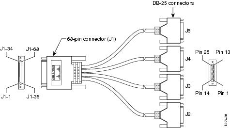
Table 38 4-Port RS-232 DTE Cable Pinout
68-Pin
|
Signal Name
|
Note
|
Direction
|
DB-25 Pin
|
Signal Name
|
J1-32
J1-31
|
GND
|
Local mode connection
|
—
|
—
|
—
|
J1-67
J1-65
|
GND
|
Local mode connection
|
—
|
—
|
—
|
J1-34
J1-68
|
GND
|
Local mode connection
|
—
|
—
|
—
|
J1-1
J1-2
J1-9
J1-16
J1-23
J1-30
J1-31
J1-35
J1-36
J1-43
J1-50
J1-57
J1-64
J1-65
J1-68
|
GND
|
Shorting block
|
—
|
—
|
—
|
J1-1
|
Shield_GND
|
Shield
|
—
|
J2-01
|
Shield_GND
|
J1-7
|
TXD/RXD
Not used
|
Twisted pair
|
—>
—
|
J2-02
|
TXD
GND
|
J1-38
|
RXD/TXD
Not used
|
Twisted pair
|
<—
—
|
J2-03
|
RXD
GND
|
J1-41
J1-8
|
RTS/CTS
DTR/DSR
|
Twisted pair
|
—>
—>
|
J2-04
J2-20
|
RTS
DTR
|
J1-4
J1-37
|
CTS/RTS
DSR/DTR
|
Twisted pair
|
<—
<—
|
J2-05
J2-06
|
CTS
DSR
|
J1-3
J1-36
|
DCD/LL
GND
|
Twisted pair
|
<—
—
|
J2-08
J2-07
|
DCD
GND
|
J1-5
|
TXC/NIL
Not used
|
Twisted pair
|
<—
—
|
J2-15
|
TXC
GND
|
J1-39
|
RXC/TXCE
Not used
|
Twisted pair
|
<—
—
|
J2-17
|
RXC
GND
|
J1-42
J1-2
|
LL/DCD
GND
|
Twisted pair
|
—>
—
|
J2-18
J2-07
|
LTST
GND
|
J1-6
|
TXCE/RXC
Not used
|
Twisted pair
|
—>
—
|
J2-24
|
TXCE
GND
|
| |
|
|
|
|
|
J1-35
|
Shield
|
|
—
|
J3-01
|
Shield_GND
|
J1-14
|
TXD/RXD
Not used
|
Twisted pair
|
—>
—
|
J3-02
|
TXD
GND
|
J1-45
|
RXD/TXD
Not used
|
Twisted pair
|
<—
—
|
J3-03
|
RXD
GND
|
J1-48
J1-15
|
RTS/CTS
DTR/DSR
|
Twisted pair
|
—>
—>
|
J3-04
J3-20
|
RTS
DTR
|
J1-11
J1-44
|
CTS/RTS
DSR/DTR
|
Twisted pair
|
<—
<—
|
J3-05
J3-06
|
CTS
DSR
|
J1-10
J1-43
|
DCD/LL
GND
|
Twisted pair
|
<—
—
|
J3-08
J3-07
|
DCD
GND
|
J1-12
|
TXC/NIL
Not used
|
Twisted pair
|
<—
—
|
J3-15
|
TXC
GND
|
J1-46
|
RXC/TXCE
Not used
|
Twisted pair
|
<—
—
|
J3-17
|
RXC
GND
|
J1-49
J1-36
|
LL/DCD
GND
|
Twisted pair
|
—>
—
|
J3-18
J3-07
|
LTST
GND
|
J1-13
|
TXCE/RXC
Not used
|
Twisted pair
|
—>
—
|
J3-24
|
TXCE
GND
|
| |
|
|
|
|
|
J1-30
|
Shield
|
|
—
|
J4-01
|
Shield_GND
|
J1-21
|
TXD/RXD
Not used
|
Twisted pair
|
—>
—
|
J4-02
|
TXD
GND
|
J1-52
|
RXD/TXD
Not used
|
Twisted pair
|
<—
—
|
J4-03
|
RXD
GND
|
J1-55
J1-22
|
RTS/CTS
DTR/DSR
|
Twisted pair
|
—>
—>
|
J4-04
J4-20
|
RTS
DTR
|
J1-18
J1-51
|
CTS/RTS
DSR/DTR
|
Twisted pair
|
<—
<—
|
J4-05
J4-06
|
CTS
DSR
|
J1-17
J1-50
|
DCD/LL
GND
|
Twisted pair
|
<—
—
|
J4-08
J4-07
|
DCD
GND
|
J1-19
|
TXC/NIL
Not used
|
Twisted pair
|
<—
—
|
J4-15
|
TXC
GND
|
J1-53
|
RXC/TXCE
Not used
|
Twisted pair
|
<—
—
|
J4-17
|
RXC
GND
|
J1-56
J1-31
|
LL/DCD
GND
|
Twisted pair
|
—>
—
|
J4-18
J4-07
|
LTST
GND
|
J1-20
|
TXCE/RXC
Not used
|
Twisted pair
|
—>
—
|
J4-24
|
TXCE
GND
|
| |
|
|
|
|
|
J1-64
|
Shield
|
|
—
|
J5-01
|
Shield_GND
|
J1-28
|
TXD/RXD
Not used
|
Twisted pair
|
—>
—
|
J5-02
|
TXD
GND
|
J1-59
|
RXD/TXD
Not used
|
Twisted pair
|
<—
—
|
J5-03
|
RXD
GND
|
J1-62
J1-29
|
RTS/CTS
DTR/DSR
|
Twisted pair
|
—>
—>
|
J5-04
J5-20
|
RTS
DTR
|
J1-25
J1-58
|
CTS/RTS
DSR/DTR
|
Twisted pair
|
<—
<—
|
J5-05
J5-06
|
CTS
DSR
|
J1-24
J1-57
|
DCD/LL
GND
|
Twisted pair
|
<—
—
|
J5-08
J5-07
|
DCD
GND
|
J1-26
|
TXC/NIL
Not used
|
Twisted pair
|
<—
—
|
J5-15
|
TXC
GND
|
J1-60
|
RXC/TXCE
Not used
|
Twisted pair
|
<—
—
|
J5-17
|
RXC
GND
|
J1-63
J1-65
|
LL/DCD
GND
|
Twisted pair
|
—>
—
|
J5-18
J5-07
|
LTST
GND
|
J1-27
|
TXCE/RXC
Not used
|
Twisted pair
|
—>
—
|
J5-24
|
TXCE
GND
|
Table 39 4-Port RS-232 DCE Cable Pinout
68-Pin
|
Signal Name
|
Note
|
Direction
|
DB-25 Pin
|
Signal Name
|
J1-32
J1-31
|
GND
|
Local mode connection
|
—
|
—
|
—
|
J1-67
J1-65
|
GND
|
Local mode connection
|
—
|
—
|
—
|
J1-1
J1-2
J1-9
J1-16
J1-23
J1-30
J1-31
J1-35
J1-36
J1-43
J1-50
J1-57
J1-64
J1-65
J1-68
|
GND
|
Shorting block
|
—
|
—
|
—
|
J1-1
|
Shield_GND
|
Shield
|
—
|
J2-01
|
Shield_GND
|
J1-38
|
RXD/TXD
Not used
|
Twisted pair
|
<—
—
|
J2-02
|
TXD
GND
|
J1-7
|
TXD/RXD
Not used
|
Twisted pair
|
—>
—
|
J2-03
|
RXD
GND
|
J1-4
J1-37
|
CTS/RTS
DSR/DTR
|
Twisted pair
|
<—
<—
|
J2-04
J2-20
|
RTS
DTR
|
J1-41
J1-8
|
RTS/CTS
DTR/DSR
|
Twisted pair
|
—>
—>
|
J2-05
J2-06
|
CTS
DSR
|
J1-42
J1-36
|
LL/DCD
GND
|
Twisted pair
|
—>
—
|
J2-08
J2-07
|
DCD
GND
|
J1-40
|
NIL/TXC
Not used
|
Twisted pair
|
—>
—
|
J2-15
|
TXC
GND
|
J1-6
|
TXCE/RXC
Not used
|
Twisted pair
|
—>
—
|
J2-17
|
RXC
GND
|
J1-3
J1-2
|
DCD/LL/
GND
|
Twisted pair
|
<—
—
|
J2-18
J2-07
|
LTST
GND
|
J1-39
|
RXC/TXCE
Not used
|
Twisted pair
|
<—
—
|
J2-24
|
TXCE
GND
|
| |
|
|
|
|
|
J1-35
|
Shield
|
|
—
|
J3-01
|
Shield_GND
|
J1-45
|
RXD/TXD
Not used
|
Twisted pair
|
<—
—
|
J3-02
|
TXD
GND
|
J1-14
|
TXD/RXD
Not used
|
Twisted pair
|
—>
—
|
J3-03
|
RXD
GND
|
J1-11
J1-44
|
CTS/RTS
DSR/DTR
|
Twisted pair
|
<—
<—
|
J3-04
J3-20
|
RTS
DTR
|
J1-48
J1-15
|
RTS/CTS
DTR/DSR
|
Twisted pair
|
—>
—>
|
J3-05
J3-06
|
CTS
DSR
|
J1-49
J1-43
|
LL/DCD
GND
|
Twisted pair
|
—>
—
|
J3-08
J3-07
|
DCD
GND
|
J1-47
|
NIL/TXC
Not used
|
Twisted pair
|
—>
—
|
J3-15
|
TXC
GND
|
J1-13
|
TXCE/RXC
Not used
|
Twisted pair
|
—>
—
|
J3-17
|
RXC
GND
|
J1-10
J1-36
|
DCD/LL/
GND
|
Twisted pair
|
<—
—
|
J3-18
J3-07
|
LTST
GND
|
J1-46
|
RXC/TXCE
Not used
|
Twisted pair
|
<—
—
|
J3-24
|
TXCE
GND
|
| |
|
|
|
|
|
J1-30
|
Shield
|
|
—
|
J4-01
|
Shield_GND
|
J1-52
|
RXD/TXD
Not used
|
Twisted pair
|
<—
—
|
J4-02
|
TXD
GND
|
J1-21
|
TXD/RXD
Not used
|
Twisted pair
|
—>
—
|
J4-03
|
RXD
GND
|
J1-18
J1-51
|
CTS/RTS
DSR/DTR
|
Twisted pair
|
<—
<—
|
J4-04
J4-20
|
RTS
DTR
|
J1-55
J1-22
|
RTS/CTS
DTR/DSR
|
Twisted pair
|
—>
—>
|
J4-05
J4-06
|
CTS
DSR
|
J1-56
J1-50
|
LL/DCD
GND
|
Twisted pair
|
—>
—
|
J4-08
J4-07
|
DCD
GND
|
J1-54
|
NIL/TXC
Not used
|
Twisted pair
|
—>
—
|
J4-15
|
TXC
GND
|
J1-20
|
TXCE/RXC
Not used
|
Twisted pair
|
—>
—
|
J4-17
|
RXC
GND
|
J1-17
J1-31
|
DCD/LL/
GND
|
Twisted pair
|
<—
—
|
J4-18
J4-07
|
LTST
GND
|
J1-53
|
RXC/TXCE
Not used
|
Twisted pair
|
<—
—
|
J4-24
|
TXCE
GND
|
| |
|
|
|
|
|
J1-64
|
Shield
|
|
—
|
J5-01
|
Shield_GND
|
J1-59
|
RXD/TXD
Not used
|
Twisted pair
|
<—
—
|
J5-02
|
TXD
GND
|
J1-28
|
TXD/RXD
Not used
|
Twisted pair
|
—>
—
|
J5-03
|
RXD
GND
|
J1-25
J1-58
|
CTS/RTS
DSR/DTR
|
Twisted pair
|
<—
<—
|
J5-04
J5-20
|
RTS
DTR
|
J1-62
J1-29
|
RTS/CTS
DTR/DSR
|
Twisted pair
|
—>
—>
|
J5-05
J5-06
|
CTS
DSR
|
J1-63
J1-57
|
LL/DCD
GND
|
Twisted pair
|
—>
—
|
J5-08
J5-07
|
DCD
GND
|
J1-61
|
NIL/TXC
Not used
|
Twisted pair
|
—>
—
|
J5-15
|
TXC
GND
|
J1-27
|
TXCE/RXC
Not used
|
Twisted pair
|
—>
—
|
J5-17
|
RXC
GND
|
J1-24
J1-65
|
DCD/LL/
GND
|
Twisted pair
|
<—
—
|
J5-18
J5-07
|
LTST
GND
|
J1-60
|
RXC/TXCE
Not used
|
Twisted pair
|
<—
—
|
J5-24
|
TXCE
GND
|
8-Port RS-232 Cable Assembly
The 8-port RS-232 cable was designed for use with the Cisco 8-port and 16-port RS-232 asynchronous HWICs (the Cisco HWIC-8A and Cisco HWIC-16A). The router end of the cable consists of a standard 68-pin 2-row D-shell connector. The network end of the cable provides eight standard 8-pin RJ-45 connectors. These cables are available in DTE format only. See Figure 26.
Figure 26 8-Port RS-232 Cable Connector, Network End
Figure 27 shows the 8-port RS-232 cable assembly. Table 40 lists the DTE pinout for the 8-port RS-232 cable. Arrows indicate signal direction: —> means DTE to DCE and <— means DCE to DTE.
Figure 27 8-Port RS-232 Cable Assembly
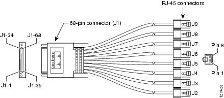
Table 40 8-Port RS-232 DTE Cable Pinout
68-Pin
|
Signal Name
|
Note
|
RJ-45 Pin
|
J1-34
J1-68
|
GND
|
Local mode connection
|
—
|
J1-67
J1-65
|
GND
|
Local mode connection
|
—
|
J1-4
J1-3
|
CTS/RTS
DSR/DTR
|
Twisted pair
|
J2-01
J2-02
|
J1-38
J1-36
|
RXD/TXD
RXD GND
|
Twisted pair
|
J2-03
J2-04
|
J1-36
J1-7
|
TXD GND
TXD/RXD
|
Twisted pair
|
J2-05
J2-06
|
J1-8
J1-41
|
DTR/DSR
RTS/CTS
|
Twisted pair
|
J2-07
J2-08
|
| |
|
|
|
J1-37
J1-5
|
CTS/RTS
DSR/DTR
|
Twisted pair
|
J3-01
J3-02
|
J1-39
J1-2
|
RXD/TXD
RXD GND
|
Twisted pair
|
J3-03
J3-04
|
J1-2
J1-6
|
TXD GND
TXD/RXD
|
Twisted pair
|
J3-05
J3-06
|
J1-40
J1-42
|
DTR/DSR
RTS/CTS
|
Twisted pair
|
J3-07
J3-08
|
| |
|
|
|
J1-11
J1-10
|
CTS/RTS
DSR/DTR
|
Twisted pair
|
J4-01
J4-02
|
J1-45
J1-43
|
RXD/TXD
RXD GND
|
Twisted pair
|
J4-03
J4-04
|
J1-43
J1-14
|
TXD GND
TXD/RXD
|
Twisted pair
|
J4-05
J4-06
|
J1-15
J1-48
|
DTR/DSR
RTS/CTS
|
Twisted pair
|
J4-07
J4-08
|
| |
|
|
|
J1-44
J1-12
|
CTS/RTS
DSR/DTR
|
Twisted pair
|
J5-01
J5-02
|
J1-46
J1-9
|
RXD/TXD
RXD GND
|
Twisted pair
|
J5-03
J5-04
|
J1-9
J1-13
|
TXD GND
TXD/RXD
|
Twisted pair
|
J5-05
J5-06
|
J1-47
J1-49
|
DTR/DSR
RTS/CTS
|
Twisted pair
|
J5-07
J5-08
|
| |
|
|
|
J1-18
J1-17
|
CTS/RTS
DSR/DTR
|
Twisted pair
|
J6-01
J6-02
|
J1-52
J1-50
|
RXD/TXD
RXD GND
|
Twisted pair
|
J6-03
J6-04
|
J1-50
J1-21
|
TXD GND
TXD/RXD
|
Twisted pair
|
J6-05
J6-06
|
J1-22
J1-55
|
DTR/DSR
RTS/CTS
|
Twisted pair
|
J6-07
J6-08
|
| |
|
|
|
J1-51
J1-19
|
CTS/RTS
DSR/DTR
|
Twisted pair
|
J7-01
J7-02
|
J1-53
J1-16
|
RXD/TXD
RXD GND
|
Twisted pair
|
J7-03
J7-04
|
J1-16
J1-20
|
TXD GND
TXD/RXD
|
Twisted pair
|
J7-05
J7-06
|
J1-54
J1-56
|
DTR/DSR
RTS/CTS
|
Twisted pair
|
J7-07
J7-08
|
| |
|
|
|
J1-25
J1-24
|
CTS/RTS
DSR/DTR
|
Twisted pair
|
J8-01
J8-02
|
J1-59
J1-57
|
RXD/TXD
RXD GND
|
Twisted pair
|
J8-03
J8-04
|
J1-57
J1-28
|
TXD GND
TXD/RXD
|
Twisted pair
|
J8-05
J8-06
|
J1-29
J1-62
|
DTR/DSR
RTS/CTS
|
Twisted pair
|
J8-07
J8-08
|
| |
|
|
|
J1-58
J1-26
|
CTS/RTS
DSR/DTR
|
Twisted pair
|
J9-01
J9-02
|
J1-60
J1-23
|
RXD/TXD
RXD GND
|
Twisted pair
|
J9-03
J9-04
|
J1-23
J1-27
|
TXD GND
TXD/RXD
|
Twisted pair
|
J9-05
J9-06
|
J1-61
J1-63
|
DTR/DSR
RTS/CTS
|
Twisted pair
|
J9-07
J9-08
|

Copyright © 2004, 2005 Cisco Systems, Inc. All rights reserved.
 Feedback