-
Cisco 7600 Series Router Software Configuration Guide Cisco IOS Release 15S
-
Preface
-
Product Overview
-
Configuring the Router for the First Time
-
Configuring a Supervisor Engine 720
-
Configuring a Route Switch Processor 720
-
Configuring NSF with SSO Supervisor Engine Redundancy
-
ISSU and eFSU on Cisco 7600 Series Routers
-
Configuring RPR and RPR+ Supervisor Engine Redundancy
-
Configuring Interfaces
-
Configuring a Supervisor Engine 32
-
Configuring LAN Ports for Layer 2 Switching
-
Configuring Flex Links
-
Configuring EtherChannels
-
Configuring VTP
-
Configuring VLANs
-
Configuring Private VLANs
-
Configuring Cisco IP Phone Support
-
Configuring IEEE 802.1Q Tunneling
-
Configuring Layer 2 Protocol Tunneling
-
Configuring L2TPv3
-
Configuring STP and MST
-
Configuring Optional STP Features
-
Configuring Layer 3 Interfaces
-
Configuring GTP-SLB IPV6 Support
-
IP Subscriber Awareness over Ethernet
-
Configuring UDE and UDLR
-
Configuring Multiprotocol Label Switching on the PFC
-
Configuring IPv4 Multicast VPN Support
-
Configuring Multicast VPN Extranet Support
-
Configuring IP Unicast Layer 3 Switching
-
Configuring IPv6 Multicast PFC3 and DFC3 Layer 3 Switching
-
Configuring IPv4 Multicast Layer 3 Switching
-
Configuring MLDv2 Snooping for IPv6 Multicast Traffic
-
Configuring IGMP Snooping for IPv4 Multicast Traffic
-
Configuring PIM Snooping
-
Configuring Network Security
-
Understanding Cisco IOS ACL Support
-
Configuring VRF aware 6RD Tunnels
-
Configuring VLAN ACLs
-
Private Hosts (Using PACLs)
-
Configuring IPv6 PACL
-
IPv6 First-Hop Security Features
-
Configuring Online Diagnostics
-
Configuring Denial of Service Protection
-
Configuring DHCP Snooping
-
Configuring Dynamic ARP Inspection
-
Configuring Traffic Storm Control
-
Unknown Unicast Flood Blocking
-
Configuring PFC QoS
-
Configuring PFC QoS Statistics Data Export
-
Configuring MPLS QoS on the PFC
-
Configuring LSM MLDP based MVPN Support
-
Configuring IEEE 802.1X Port-Based Authentication
-
Configuring IEEE 802.1ad
-
Configuring Port Security
-
Configuring UDLD
-
Configuring NetFlow and NDE
-
Configuring Local SPAN, RSPAN, and ERSPAN
-
Configuring SNMP IfIndex Persistence
-
Power Management and Environmental Monitoring
-
Configuring Web Cache Services Using WCCP
-
Using the Top N Utility
-
Using the Layer 2 Traceroute Utility
-
Configuring Bidirectional Forwarding and Detection over Switched Virtual Interface
-
Configuring Call Home
-
Configuring IPv6 Policy Based Routing
-
Using the Mini Protocol Analyzer
-
Configuring Resilient Ethernet Protocol
-
Configuring Synchronous Ethernet
-
Configuring Link State Tracking
-
Configuring BGP PIC Edge and Core for IP and MPLS
-
Configuring VRF aware IPv6 tunnels over IPv4 transport
-
ISIS IPv4 Loop Free Alternate Fast Reroute (LFA FRR)
-
Multicast Service Reflection
-
Y.1731 Performance Monitoring
-
Online Diagnostic Tests
-
Acronyms
-
Cisco IOS Release 15S Software Images
-
 Feedback
Table Of Contents
Understanding Y.1731 Performance Monitoring
Frame Delay and Frame Delay Variation
Frame Loss Ratio and Availability
Guidelines and Restrictions for LMM over Port-Channel
Restrictions and Usage Guidelines
Y.1731 Performance Monitoring
This chapter describes how to configure the Y.1731 Performance Monitoring in Cisco IOS Software Release 15.1(2)S.
This chapter includes the following sections:
•
Understanding Y.1731 Performance Monitoring
Understanding Y.1731 Performance Monitoring
When service providers sell connectivity services to a subscriber, a Service Level Agreement (SLA) is reached between the buyer and seller of the service. The SLA defines the attributes offered by a provider and serves as a legal obligation on the service provider. As the level of performance required by subscribers increases, service providers need to monitor the performance parameters being offered. In order to capture the needs of the service providers, organizations have defined various standards such as IEEE 802.1ag and ITU-T Y.1731 that define the methods and frame formats used to measure performance parameters.
Y.1731 Performance Monitoring (PM) provides a standard ethernet PM function that includes measurement of ethernet frame delay, frame delay variation, frame loss, and frame throughput measurements specified by the ITU-T Y-1731 standard and interpreted by the Metro Ethernet Forum (MEF) standards group. As per recommendations, the 7600 platform should be able to send, receive and process PM frames in intervals of 10ms (100 frames per second) with the maximum recommended transmission period being 100ms (10 frames per second) for any given service.
To measure SLA parameters such as frame delay or frame delay variation, a small number of synthetic frames are transmitted along with the service to the end point of the maintenance region, where the Maintenance End Point (MEP) responds to the synthetic frame. For a function such as connectivity fault management, the messages are sent less frequently, while performance monitoring frames are sent more frequently.
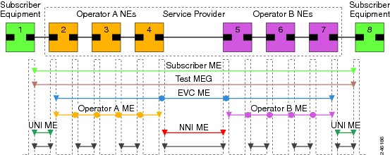
Figure 73-1 illustrates Maintenance Entities (ME) and Maintenance End Points (MEP) typically involved in a point-to-point metro ethernet deployment for the Y.1731 standard.
Figure 73-1 A Point-to-Point Metro Ethernet Deployment with Typical Maintenance Entities and Maintenance Points
Following are the performance monitoring parameters:
•
•
•
Connectivity
The first step to performance monitoring is verifying the connectivity. Continuity Check Messages (CCM) are best suited for connectivity verification, but is optimized for fault recovery operation. It is usually not accepted as a component of an SLA due to the timescale difference between SLA and Fault recovery. Hence, Connectivity Fault Management (CFM) and Continuity Check Database (CCDB) are used to verify connectivity. For more information on CFM see: http://www.cisco.com/en/US/docs/routers/7600/install_config/ES40_config_guide/es40_chap4.html#wp1608025
Frame Delay and Frame Delay Variation
Ethernet frame Delay Measurement (ETH-DM) is used for on-demand ethernet Operations, Administration & Maintenance (OAM) to measure frame delay and frame delay variation.
Ethernet frame delay and frame delay variation are measured by sending periodic frames with ETH-DM information to the peer MEP and receiving frames with ETH-DM information from the peer MEP. During the interval, each MEP measures the frame delay and frame delay variation.
Ethernet frame delay measurement also collects useful information, such as worst and best case delays, average delay, and average delay variation. Ethernet frame delay measurement supports hardware-based timestamping in the ingress direction. It provides a runtime display of delay statistics during a two-way delay measurement. Ethernet frame delay measurement records the last 100 samples collected per remote Maintenance End Point (MEP) or per CFM session.
These are the two methods of delay measurement, as defined by the ITU-T Y.1731 standard:
•
Each MEP transmits frames with one-way ETH-DM information to its peer MEP in a point-to-point ME to facilitate one-way frame delay and/or one-way frame delay variation measurements at the peer MEP. One way frame delay requires clock to be synchronized at both ends while frame delay variation doesn't require clock synchronization. It is measured using a single delay measurement (1DM) or Delay Measurement Message (DMM) and Delay Measurement Reply (DMR) frame combination.•
Each MEP transmits frames with ETH-DM request information to its peer MEP and receives frames with ETH-DM reply information from its peer MEP. Two way frame delay and frame delay variation is measured using DMM and DMR frame.These are the pre-requisites for 1DM measurements:
–
–
–
Note
For a 7600 router that does not have 2-Port Gigabit Synchronous Ethernet SPA, delay measurement is done by using the timestamps with Network Time Protocol (NTP) as the time source protocol. This is applicable only to One-way delay measurements.
To initiate Time of Day (ToD) synchronization on a line card, use the platform time-source command in global configuration mode. For more information on the platform time source command see: http://www.cisco.com/en/US/docs/ios/interface/command/reference/ir_o1.htmlFrame Loss Ratio and Availability
Ethernet frame Loss Measurement (ETH-LM) is used to collect counter values applicable for ingress and egress service frames where the counters maintain a count of transmitted and received data frames between a pair of MEPs.
ETH-LM transmits frames with ETH-LM information to a peer MEP and similarly receives frames with ETH-LM information from the peer MEP. Each MEP performs frame loss measurements which contribute to unavailable time. A near-end frame loss refers to frame loss associated with ingress data frames. Far-end frame loss refers to frame loss associated with egress data frames. Both near-end and far-end frame loss measurements contribute to near-end severely errored seconds and far end severely errored seconds which together contribute to unavailable time.
These are the two methods of frame loss measurement, defined by the ITU-T Y.1731 standard:
•
•
Y.1731 PM Synthetic Loss Measurement
Synthetic Loss Measurement (SLM) is an extension of the existing Y.1731 PM feature, and makes use of an additional functionality defined in the latest version of the ITU-T Y.1731 (2011) standard. SLM measures frame loss using synthetic frames, rather than data traffic. Frame loss is measured by calculating the difference between the number of synthetic frames that are sent and received.
Single-ended ETH-SLM
Single-ended ETH-SLM carries out synthetic loss measurements applicable to both point-to-point ETH connection or multipoint ETH connectivity. The MEP sends frames with the ETH-SLM request information to its peer MEPs and receives frames with ETH-SLM reply information from its peer MEPs to measure synthetic loss.
Supported Interfaces
Y.1731 PM supports these interfaces:
•
•
•
•
•
•
•
•
Note
Guidelines and Restrictions for LMM over Port-Channel
•
•
Note
Y.1731 PM SLM supports these interfaces:
•
•
•
•
•
•
•
•
•
•
Restrictions and Usage Guidelines
Follow these restrictions and usage guidelines when you configure Y.1731 PM on an ES+ line card:
•
•
•
•
•
•
•
–
–
–
–
•
•
•
•
These are the restrictions for PM support on Port-channel:
•
•
•
•
•
Configuring Y.1731 PM
For information on Y.1731 PM configurations, see: http://www.cisco.com/en/US/docs/routers/7600/install_config/ES40_config_guide/es40_chap4.html#wp1708139