-
Cisco Prime Infrastructure 2.0 User Guide
-
Preface
- Getting Started
- Designing the Network
-
Operating the Network
-
Operating and Monitoring the Network
-
Monitoring Alarms
-
Updating Device Inventory
-
Configuring Device Features
-
Working With Device Configurations
-
Maintaining Software Images
-
Working with Wireless Operational Tools
-
Ensuring Consistent Application Experiences
-
Working with Wireless Mobility
-
Configuring the Cisco AppNav Solution
-
Configuring WAAS Container
-
Troubleshooting
-
Reports
-
-
Prime Infrastructure User Interface Reference
-
 Feedback
Table Of Contents
Specifying Which Interfaces and Ports to Monitor
Setting Up WAN Interface Monitoring
Getting Enhanced Client Information by Integrating with ISE
Adding an Identity Services Engine
Setting Up Assurance for Performance Monitoring
Enabling NetFlow Data Collection
Configuring NetFlow on Catalyst 3000, 4000, and 6000 Family of Switches
Configuring NetFlow on ISR Devices
Setting Up Network Monitoring
After you add devices to the Cisco Prime Infrastructure inventory and set up device and port groups, you need to set up your devices to allow Prime Infrastructure to monitor the devices.
•
Specifying Which Interfaces and Ports to Monitor
You can also configure Prime Infrastructure to monitor more advanced information:
•
•
Specifying Which Interfaces and Ports to Monitor
You create monitoring templates to monitor device features, usage, health, and other factors. After you create and deploy monitoring templates, Prime Infrastructure collects and processes data from specified devices and displays the information in dashboards, dashlets (see Dashboards and Dashlets), and reports.
To monitor your device ports, you can create a port group and then display monitoring information on the Prime Infrastructure dashboard. Port groups are logical groupings of interfaces that allow you to monitor device ports by the function they serve. For example, you can create a port group for the WAN ports and create another port group for the internal distribution ports on the same router.
When you create a port group, you must determine which types of ports you want to monitor. The following port groups are typical of most networks:
•
•
•
After you create port groups, you can more efficiently configure all of the devices belonging to a port group.
Setting Up WAN Interface Monitoring
Creating a WAN interface port group allows you to efficiently configure settings on all WAN interfaces in a specific port group. For example, a small branch office might have a problem where the WAN bandwidth is as low as 1.544 Mb/s, and a round trip latency of 300 ms. To watch the WAN bandwidth used by this branch, you set up the interface from the router that connects to the ISP as a WAN interface.
The following procedure shows you how to:
1.
2.
3.
Step 1
a.
b.
Step 2
a.
b.
c.
d.
e.
f.
Step 3
a.
> Add Dashlets.
b.
–
–
Getting Enhanced Client Information by Integrating with ISE
You can get enhanced information about managed clients using the Cisco Identify Services Engine (ISE) or ACS View servers.
Adding an Identity Services Engine
A maximum of two ISEs can be added toPrime Infrastructure. If you add two ISEs, one should be primary and the other should be standby. When you are adding a standalone node, you can add only one standalone node and cannot add a second node.
To add an Identity Services Engine, follow these steps:
Step 1
Step 2
Step 3
Note
Configuring ACS View Servers
If you do not have ISE, you can integrate your Cisco Secure Access Control ACS View server with Prime Infrastructure. To access the ACS View Server tab, you must add a view server with credentials.
Note
To configure an ACS View Server, follow these steps:
Step 1
Step 2
Step 3
Step 4
Step 5
Step 6
Setting Up Assurance for Performance Monitoring
If your Prime Infrastructure implementation includes Assurance licenses, you must enable data collection via NAMs and NetFlow configurations. This is necessary to populate the additional dashlets, reports, and other features supplied with Assurance.
Enabling NAM Data Collection
To ensure that you can collect data from your Network Analysis Modules (NAMs), you must enable NAM data collection. You can do this for each discovered or added NAM, or for all NAMs at the same time.
Before You Begin
You must specify the HTTP/HTTPS credentials for each NAM (see Adding NAM HTTP/HTTPS Credentials).
Step 1
Step 2
Step 3
Enabling NetFlow Data Collection
To start collecting NetFlow and Flexible NetFlow data, you must configure your NetFlow-enabled switches, routers, and other devices (ISR/ASR) to export this data to Prime Infrastructure. The following table shows the various device types that support NetFlow and the ways to configure devices to export NetFlow data to Prime Infrastructure.
Table 5-1 NetFlow Support Summary
Catalyst 3750-X / 3560-X
15.0(1)SE
IP base or IP services feature set and equipped with the network services module.
TCP and UDP traffic
See Configuring NetFlow on Catalyst 3000, 4000, and 6000 Family of Switches.
Catalyst 3850
15.0(1)EX
TCP and UDP traffic, Voice & Video
To configure TCP and UDP traffic, see Configuring NetFlow on Catalyst 3000, 4000, and 6000 Family of Switches.
To configure Voice & Video, use this CLI template:
Design > Feature Design > CLI Templates > System Templates - CLI >Medianet - PerfMon
Catalyst 4500
15.0(1)XO and 15.0(2)
TCP and UDP traffic, Voice & Video
To configure TCP and UDP traffic, see Configuring NetFlow on Catalyst 3000, 4000, and 6000 Family of Switches.
To configure Voice & Video, use this CLI template:
Design > Feature Design > CLI Templates > System Templates - CLI >Medianet - PerfMon
Catalyst 6500
SG15.1(1)SY
TCP and UDP traffic, Voice & Video
To configure TCP and UDP traffic, see Configuring NetFlow on Catalyst 3000, 4000, and 6000 Family of Switches.
To configure Voice & Video, use this CLI template:
Design > Feature Design > CLI Templates > System Templates - CLI >Medianet - PerfMon
ISR
15.1(3) T
TCP and UDP traffic, Voice & Video
To configure TCP and UDP traffic, use this CLI template:
Design > Feature Design > CLI Templates > System Templates - CLI > Collecting Traffic Statistics
To configure Voice & Video, use this CLI template:
Design > Feature Design > CLI Templates > System Templates - CLI >Medianet - PerfMon
ISR G2
15.2(1) T and 15.1(4)M
TCP and UDP traffic, application response time, Voice and Video
To configure TCP, UDP, and ART, see Configuring NetFlow on ISR Devices.
To configure Voice & Video, use this CLI template:
Design > Feature Design > CLI Templates > System Templates - CLI >Medianet - PerfMon
ISR G2
15.2(4) M2 or later, 15.3(1)T or later
TCP and UDP traffic, application response time, Voice and Video
To configure TCP, UDP, and ART, see Configuring Application Visibility.
ASR
15.3(1)S1 or later
TCP and UDP traffic, application response time, Voice & Video, HTTP URL visibility
ISR G3
15.3(2)S or later
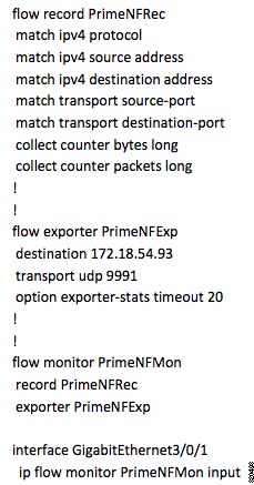
Configuring NetFlow on Catalyst 3000, 4000, and 6000 Family of Switches
To manually configure NetFlow to export TCP and UDP traffic on Catalyst 3000, 4000, or 6000 devices, use the following steps to create a user-defined CLI template:
Step 1
Step 2
Step 3
Step 4
Figure 5-1 Catalyst 3000, 4000, and 6000 CLI Commands
Step 5
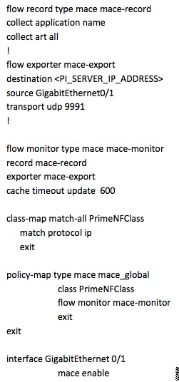
Configuring NetFlow on ISR Devices
To manually configure NetFlow to export MACE traffic on an ISR device, use the following steps to create a user-defined CLI template:
Step 1
Step 2
Step 3
Step 4
Figure 5-2 ISR MACE CLI Commands
Step 5