-
Cisco IP Solution Center MPLS VPN User Guide, 4.0
-
Index
-
About This Guide
-
IP Solution Center - MPLS VPN
-
Provisioning an Unmanaged Multi-VRF CE
-
MPLS VPN Service Policies
-
MPLS VPN Service Requests
-
Provisioning Regular PE-CE Links
-
Provisioning MVRFCE PE-CE Links
-
Provisioning Management VPN
-
Provisioning Cable Services
-
Provisioning Carrier Supporting Carrier
-
Spanning Multiple Autonomous Systems
-
Setting Up the Network
-
Service Request Transition States
-
Troubleshooting MPLS VPN
-
 Feedback
Table Of Contents
Provisioning an Unmanaged Multi-VRF CE
Creating a Customer, Site, and CPE
Collect the Latest Configuration
Create a Route Distinguisher Pool
Defining an MVRFCE PE-CE Service Policy
Creating an MVRFCE PE-CE Service Request
Provisioning an Unmanaged Multi-VRF CE
This chapter describes how to implement a new, Unmanaged Multi-VRF (MVRF) CE with all the required infrastructure data, define an MVRFCE PE-CE Service Policy, and create an MVRFCE PE-CE Service Request, using the Cisco IP Solution Center (ISC).
This chapter contains the following major sections:
•
Defining an MVRFCE PE-CE Service Policy
•
Unmanaged MVRFCE Overview
The unmanaged MVRFCE feature is similar to the unmanaged CE feature in so far as the service provider does not use ISC to upload or download configurations to the CPE. This feature is similar to the managed MVRFCE feature in so far as ISC creates a link with three devices: a PE, an MVRFCE, and a CE.
In the unmanaged scenarios, the customer configures the CPE manually. To automate the process of configuring the unmanaged MVRFCE, the service provider can use ISC to generate the configuration and then send it to the customer for manual implementation.
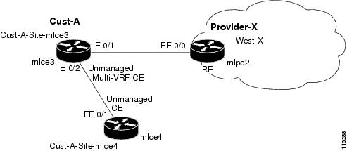
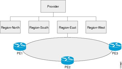
Figure 2-1 shows an overview of a network topology with MPLS VPN MVRFCE PE-CE links.
Figure 2-1 Unmanaged MVRFCE PE-CE Network Topology
The network topology in Figure 2-1 shows a service provider (Provider-X) and a customer (Cust-A). The Provider contains one Region (West-X) and one PE (mlpe2). The Customer contains an MVRFCE (mlce3) and a CE (mlce4). Both of these CPEs are unmanaged.
This section contains the following sections:
Process Overview
To configure MPLS VPN services with ISC, you must understand three key concepts:
Network Inventory
The purpose of preparing network inventory in ISC is to populate the Repository with infrastructure data. If multiple devices are involved, you can use Inventory Manager for importing devices and creating PE or CPE. Otherwise, you can use Inventory and Connection Manager to create the devices and infrastructure data.
To create an MPLS VPN Service Request, you must create the following infrastructure data:
•
A Device in ISC is a logical representation of a physical device in the network. You can import devices (configurations) into ISC by using Inventory Manager or the ISC GUI. You can also use the Auto Discovery feature of Inventory Manager to import devices into the Repository.
•
A customer is typically an enterprise or large corporation that receives network services from a service provider. A Customer is also a key logical component of ISC.
–
A Site is a logical component of ISC that connects a Customer with a CE. It can also represent a physical customer site.
–
A CPE is "customer premises equipment," typically a customer edge router (CE). It is also a logical component of ISC. You can create CPE in ISC by associating a device with a Customer Site.
•
A provider is typically a "service provider" or large corporation that provides network services to a customer. A Provider is also a key logical component of ISC.
–
A Region is a logical component of ISC that connects a Provider with a PE. It can also represent a physical provider region.
–
A PE is a provider edge router or switch. It is also a logical component of ISC. You can create PE in ISC by associating a Device with a Provider Region. In ISC, a PE can be a "point of presence" router (POP) or a Layer 2 switch (CLE).
•
The Layer 2 Ethernet switching domain that connects a PE to a CE is called an Access Domain. All the switches attached to the PE-POP belong to this Access Domain. These switches belong to the Provider and are defined in ISC as PE-CLE.
•
–
–
–
–
–
•
•
Before creating a Service Policy, a VPN name must be defined within ISC.
Service Policy
To create an MVRFCE PE-CE Service Policy, you must set up the following items:
1.
2.
3.
4.
5.
6.
7.
8.
Service Request
To create an MVRFCE PE-CE Service Request, you must complete the following items:
1.
2.
3.
4.
5.
6.
7.
MVRFCE PE-CE Policy Type
An MVRFCE PE-CE Policy Type is a PE to CE link with three devices:
•
•
•
Figure 2-2 shows an example of an MVRFCE PE-CE link with three devices.
Figure 2-2 MVRFCE PE-CE Link
In an MVRFCE PE-CE Service Policy with CE Present enabled, interfaces FE 0/0, E 0/1, E 0/2 and FE 0/1 are configured as an MPLS VPN link in the Service Request process.
Infrastructure Data
In this MVRFCE PE-CE scenario, the following infrastructure data is used:
•
•
•
•
•
•
•
•
•
•
•
•
–
–
–
–
–
•
–
–
–
•
–
–
–
•
–
Adding a New Customer CPE
This section describes how to create a new CPE with an Unmanaged Multi-VRF management Type using the Cisco IP Solution Center (ISC) GUI. It contains the following sections:
•
Overview of an ISC Customer
In ISC, a Customer is defined by the following three logical components:
•
•
•
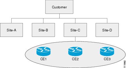
In ISC, a Customer is a logical container for Sites and CEs.
Within a Customer, there can be one or more Sites. Sites are logical entities that can be defined in any way that makes sense to a service provider.
Figure 2-3 shows an overview of an ISC Customer.
Figure 2-3 Overview of an ISC Customer
Creating a Device
This section describes how to create a Device with the ISC GUI, connect to a Cisco IOS router in the network, collect the live configuration, and populate the Repository. This section contains the following sections:
Create a Device
This section describes how to create a logical Device with the ISC GUI. To create a Device with the ISC GUI, follow these steps:
Step 1
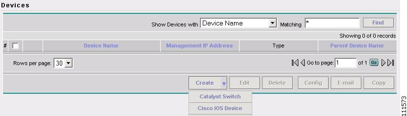
Step 2
The Devices window appears, as shown in Figure 2-4.
Figure 2-4 Devices
Step 3
Step 4
The Create Cisco IOS Device window appears (not shown).
Step 5
•
–
–
•
–
–
–
–
•
–
–
–
•
–
–
Step 6
Note
Collect the Configuration
This section describes how to connect to the physical device in the network, collect the device information from the router, and populate the Repository.
To collect the configuration, follow these steps:
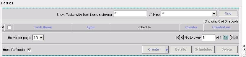
Step 1
The Tasks window appears, as shown in Figure 2-5.
Figure 2-5 Tasks
Step 2
Step 3
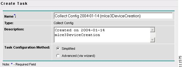
The Create Task window appears, as shown in Figure 2-6.
Note
Figure 2-6 Create Task
Step 4
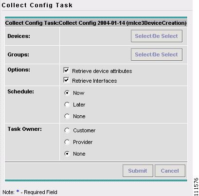
The Collect Config Task window appears, as shown in Figure 2-7.
Figure 2-7 Collect Config Task
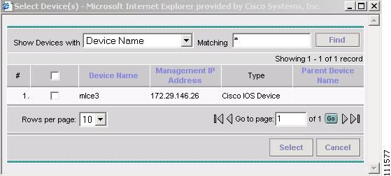
Step 5
The Select Device window appears, as shown in Figure 2-8.
Figure 2-8 Select Device
Step 6
The Collect Config Task window appears (not shown).
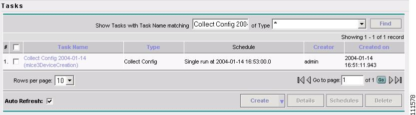
Step 7
The Task window appears, as shown in Figure 2-9.
Figure 2-9 Tasks
Step 8
Note
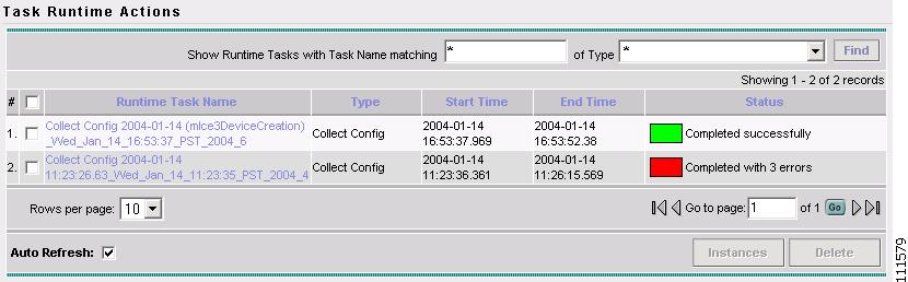
Monitor Task Logs
To monitor the logs for your task, follow these steps:
Step 1
The Tasks window appears (not shown).
Step 2
The Task Runtime Actions window appears, as shown in Figure 2-10.
Figure 2-10 Task Runtime Actions
Note
Step 3
Creating a Customer, Site, and CPE
This section describes how to create a Customer with the ISC GUI, create a Site for the Customer, and associate a Device with the Site. This section contains the following sections:
Create a Customer
To create a Customer with the ISC GUI, follow these steps:
Step 1
The Customers window appears (not shown).
Step 2
The Create Customer window appears (not shown).
Step 3
Note
The Customers window appears (not shown).
Create a Site
To create a Site, follow these steps:
Step 1
Step 2
The Customer Site window appears (not shown).
Step 3
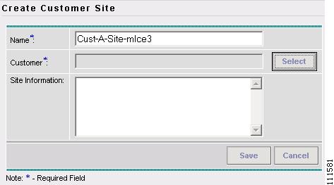
The Create Customer Site window appears, as shown in Figure 2-11.
Figure 2-11 Create Customer Site
Step 4
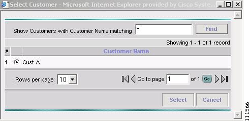
Step 5
The Select Customer window appears, as shown in Figure 2-12.
Figure 2-12 Select Customer
Step 6
Step 7
The Create Customer Site window appears.
Click Save.
Note
Create a CPE
To create a CPE, follow these steps:
Step 1
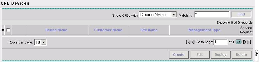
Step 2
The CPE Devices window appears, as shown in Figure 2-13.
Figure 2-13 CPE Devices
Step 3
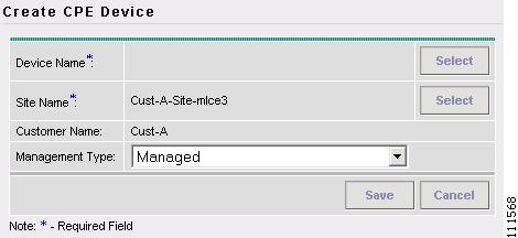
The Create CPE Device window appears, as shown in Figure 2-14.
Figure 2-14 Create CPE Device
Step 4
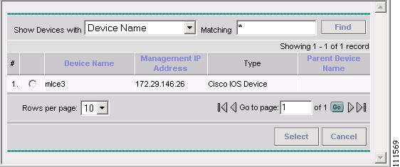
The Select Device window appears, as shown in Figure 2-15.
Figure 2-15 Select Device
Step 5
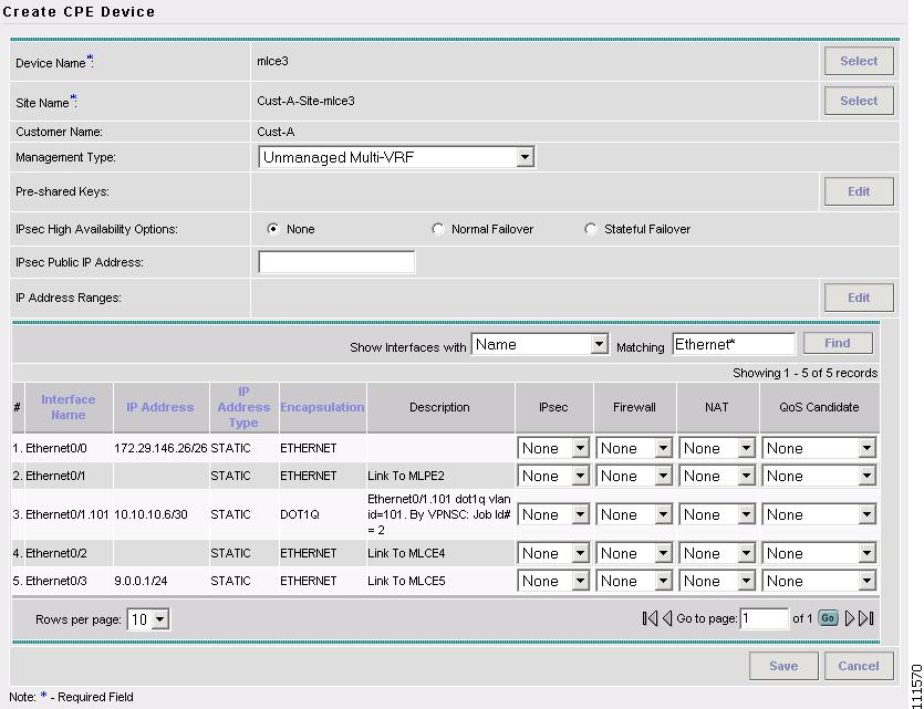
The Create CPE Device window appears, as shown in Figure 2-16.
Figure 2-16 Create CPE Device
Step 6
Step 7
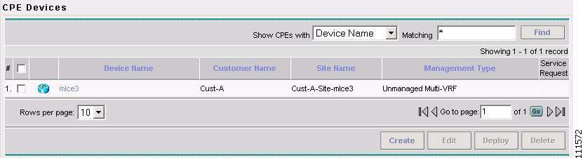
The Create CPE Device window appears, as shown in Figure 2-17.
Figure 2-17 CPE Devices
Note
Adding a New Provider PE
This section describes how to use Cisco IP Solution Center (ISC) Inventory Manager to create a PE from a Device and configure a Provider in the process.
This section contains the following sections:
•
Overview of an ISC Provider
In ISC, a Provider is defined by the following three logical components:
•
•
•
In ISC, a provider administrative domain (PAD) is a single AS. It is not a specific service provider, rather it is a logical container for Regions and PEs.
Within a single PAD, there must be one or more Regions. Regions are logical entities that can be defined in any way that makes sense to a service provider.
Within a Region, a Provider can contain one or more PEs. The PEs can be a PE-POP ("router") or a PE-CLE ("switch").
Figure 2-3 shows an overview of an ISC Provider.
Figure 2-18 Overview of an ISC Provider
Create a Device Group
This section describes how to create a Device Group with Inventory Manager. To create a Device Group, follow these steps:
Step 1
Step 2
The Inventory Manager Java Web Start window appears (not shown).
Step 3
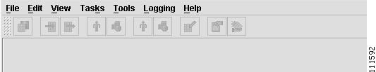
The Inventory Manager task bar appears, as shown in Figure 2-19.
Figure 2-19 Inventory Manager Task Bar
Step 4
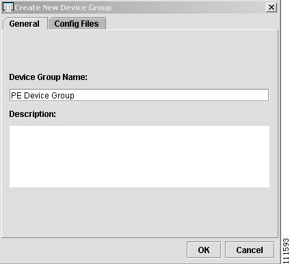
The Create New Device Group window appears, as shown in Figure 2-20.
Figure 2-20 Create New Device Group
Step 5
Step 6
The No Config Files Specified for Import window appears (not shown).
Step 7
The Choose Config Files for Device Group window appears (not shown).
Note
Import Configuration Files
This section describes how to import configuration files with Inventory Manager.
To import configuration files, follow these steps:
Step 1
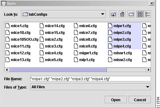
The Open window appears, as shown in Figure 2-21.
Figure 2-21 Open Config Files
Step 2
Step 3
The Choose Config Files for Device Group window appears (not shown).
Step 4
The Group spreadsheet appears, as shown in Figure 2-22.
Figure 2-22 Group Spreadsheet
Step 5
Note
Open a Device
Note
This section describes how to open a Device with Inventory Manager.
To open a Device, follow these steps:
Step 1
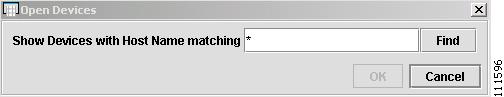
The Open Devices window appears, as shown in Figure 2-23.
Figure 2-23 Open Devices
Step 2
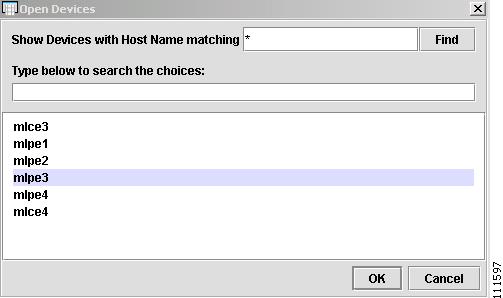
The Open Devices window appears, as shown in Figure 2-24.
Figure 2-24 Open Devices
Step 3
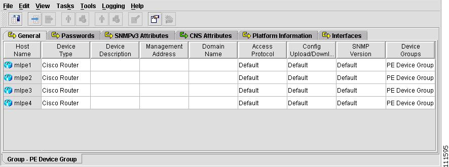
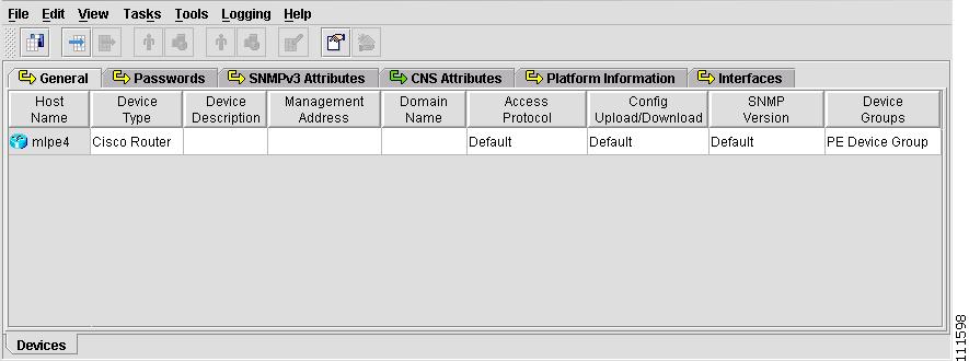
The Devices spreadsheet appears, as shown in Figure 2-25.
Figure 2-25 Devices Spreadsheet
Note
Collect the Latest Configuration
This section describes how to connect to a physical device in the network, and collect the latest configuration, with Inventory Manager.
To collect a configuration, follow these steps:
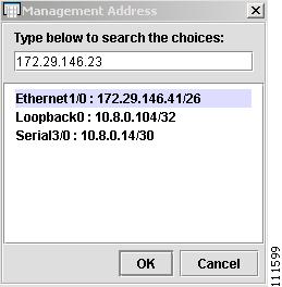
Step 1
The Management Address window appears, as shown in Figure 2-26.
Note
Figure 2-26 Management Address
Step 2
The Devices spreadsheet appears (not shown).
Step 3
The Passwords spreadsheet appears (not shown).
Step 4
The Login Password window appears (not shown).
Step 5
Step 6
Step 7
Step 8
The Enable Password window appears (not shown).
Step 9
Step 10
Step 11
Step 12
Step 13
Step 14
You are notified if the task completes successfully.
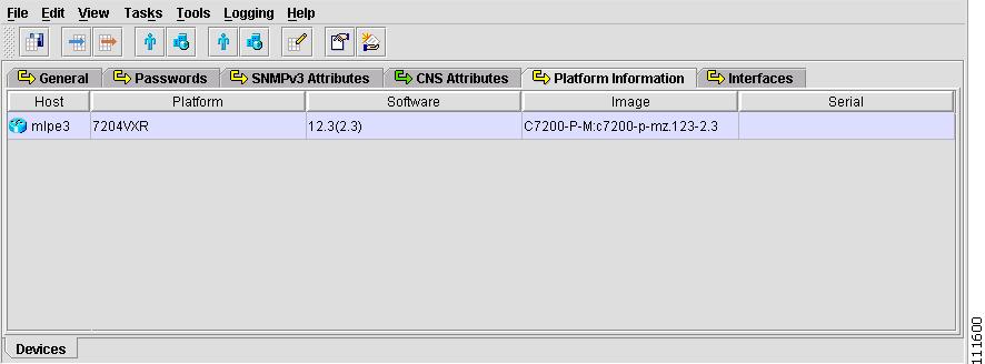
Step 15
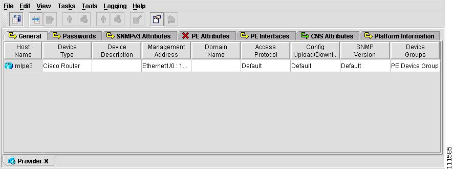
The Platform Information spreadsheet appears, as shown in Figure 2-27 below.
Step 16
Note
Create a Provider and a PE
This section describes how to create a Provider and a PE from a Device, using Inventory Manager.
To create a Provider and a PE, follow these steps:
Step 1
Figure 2-27 Platform Information
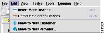
Step 2
Figure 2-28 Move to New Customer
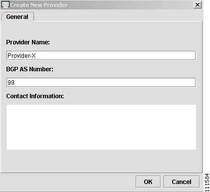
The Create New Provider window appears, as shown in Figure 2-29.
Figure 2-29 Create New Provider
Enter the Provider Name and BGP AS Number. (Provider-X, 99)
Step 3
The Provider spreadsheet appears with a PE, as shown in Figure 2-30.
Figure 2-30 Provider Spreadsheet
Step 4
Note
Create a Region for the PE
This section describes how to create a Region for the PE with Inventory Manager.
To create a Region, follow these steps:
Step 1
The PE Attributes spreadsheet appears, as shown in Figure 2-31.
Figure 2-31 PE Attributes
Step 2
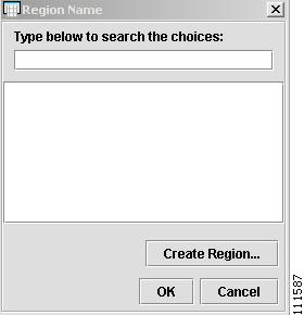
The Region Name window appears, as shown in Figure 2-32.
Figure 2-32 Region Name
Step 3
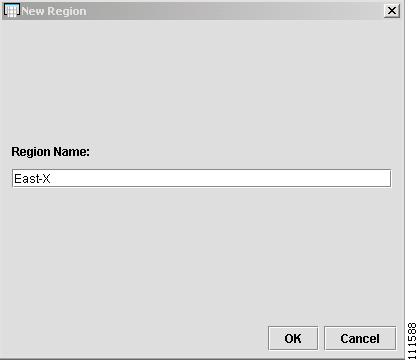
The New Region window appears, as shown in Figure 2-33.
Figure 2-33 New Region
Step 4
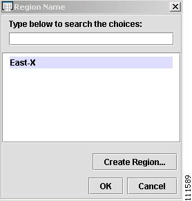
The Region Name window appears, as shown in Figure 2-34.
Figure 2-34 Region Name
Step 5
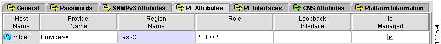
The PE Attributes spreadsheet appears, as shown in Figure 2-35.
Figure 2-35 PE Attributes
Step 6
Note
Edit a PE with the ISC GUI
This section describes how to view or edit a PE with the ISC GUI.
To view a PE with the ISC GUI, follow these steps:
Step 1
Step 2
Step 3
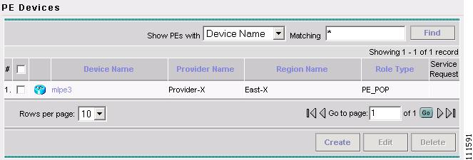
The PE Devices window appears, as shown in Figure 2-36.
Figure 2-36 PE Devices
Step 4
Step 5
Creating an Access Domain
Note
This section describes how to create an Access Domain using the Cisco IP Solution Center (ISC) GUI. This section contains the following sections:
Overview of an Access Domain
Any Transport over MPLS (AToM) is the Cisco solution for transporting Layer 2 traffic over an IP/MPLS backbone. AToM is required for supporting legacy services over MPLS infrastructures and for supporting new connectivity options, including Layer 2 VPNs and Layer 2 virtual leased lines.
AToM supports three types of Ethernet-based L2VPNs (EoMPLS):
•
•
•
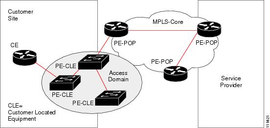
The Layer 2 Ethernet switching domain that connects a PE to a CE is called an Access Domain. All the switches attached to the PE-POP belong to this Access Domain. These switches belong to the Provider and are defined in ISC as PE-CLE.
Note
ISC supports multiple PE-POPs per Access Domain and multiple PE-CLE devices can be included.
Figure 2-37 shows an overview of an ISC Access Domain.
Figure 2-37 Overview of an Access Domain
Create an Access Domain
This section describes how to create a Device with the ISC GUI.
To create a Device with the ISC GUI, follow these steps:
Step 1
Step 2
Step 3
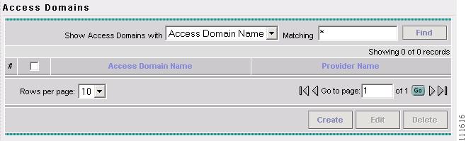
The Access Domains window appears, as shown in Figure 2-38.
Figure 2-38 Access Domains
Step 4
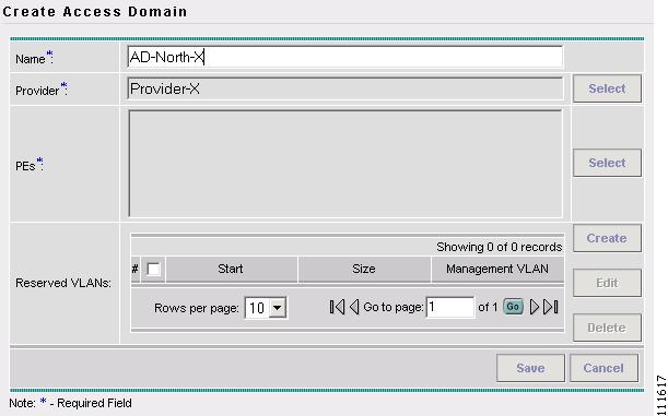
The Create Access Domain window appears, as shown in Figure 2-39.
Figure 2-39 Create Access Domain
Step 5
Step 6
Step 7
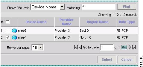
The Show PEs window appears, as shown in Figure 2-40.
Figure 2-40 Show PEs
Step 8
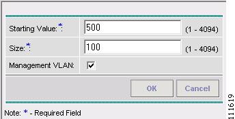
Step 9
The Create Reserved VLAN window appears, as shown in Figure 2-41.
Figure 2-41 Create Reserved VLAN
Step 10
Step 11
Step 12
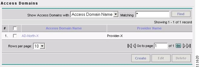
Step 13
The Access Domains window appears, as shown in Figure 2-8.
Figure 2-42 Access Domains
The Access Domain has been saved in the Repository.
Creating Resource Pools
This section describes how to create Resource Pools using the Cisco IP Solution Center (ISC) GUI.
This section contains the following sections:
•
Overview of Resource Pools
Before creating a service in ISC, you must define your Resource Pools. From these Resource Pools, ISC can automatically assign some values during the provisioning process. You can also manually assign these values during the provisioning process, but it is not recommended.
ISC allocates numbers from the following pools during the provisioning process:
•
•
•
•
•
•
•
Create an IP Address Pool
This section describes how to create an IP Address Pool with the ISC GUI.
To create an IP Address Pool with the ISC GUI, follow these steps:
Step 1
Step 2
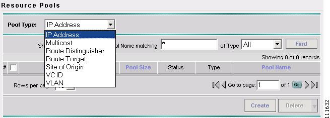
The Resource Pools window appears, as shown in Figure 2-43.
Figure 2-43 Resource Pools
Step 3
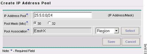
Step 4
The Create IP Address Pool window appears, as shown in Figure 2-44.
Figure 2-44 Create IP Address Pool
Step 5
Step 6
Note
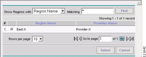
Step 7
The Select Region window appears, as shown in Figure 2-45.
Figure 2-45 Select Region
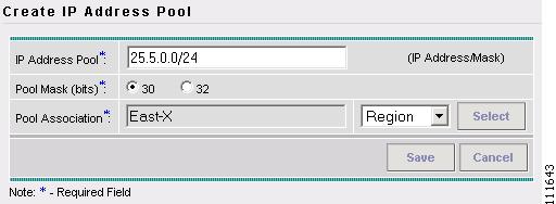
Step 8
Step 9
The Create IP Address Pool window appears, as shown in Figure 2-6.
Figure 2-46 Create IP Address Pool
Step 10
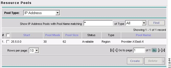
The Resource Pools - IP Address window appears, as shown in Figure 2-47.
Figure 2-47 Resource Pools - IP Address
You have saved an IP Address Pool in the Repository.
Create a Multicast Pool
This section describes how to create a Multicast Address Pool with the ISC GUI.
To create a Multicast Pool with the ISC GUI, follow these steps:
Step 1
Step 2
The Resource Pools window appears (not shown).
Step 3
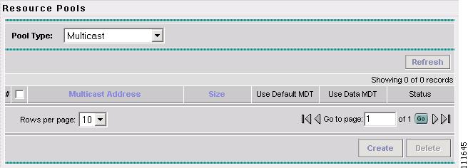
The Resource Pools - Multicast window appears, as shown in Figure 2-8.
Figure 2-48 Resource Pools - Multicast
Step 4
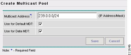
The Create Multicast Pool window appears, as shown in Figure 2-49.
Figure 2-49 Create Multicast Pool
Step 5
Step 6
Step 7
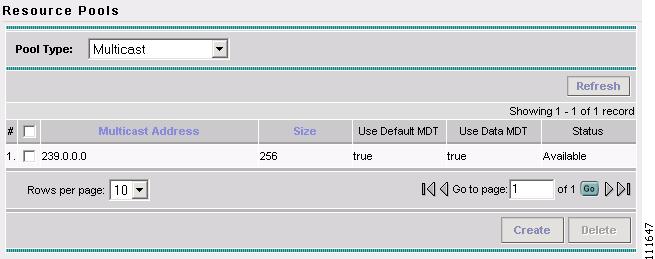
The Resource Pools - Multicast window appears, as shown in Figure 2-48.
Figure 2-50 Resource Pools - Multicast
You have saved a Multicast Address Pool in the Repository.
Create a Route Distinguisher Pool
This section describes how to create a Route Distinguisher Pool with the ISC GUI.
To create a Route Distinguisher Pool with the ISC GUI, follow these steps:
Step 1
Step 2
The Resource Pools window appears (not shown).
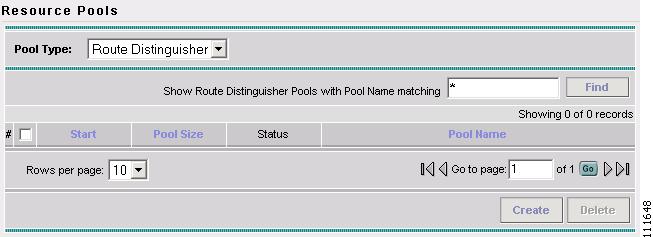
Step 3
The Resource Pools - Route Distinguisher window appears, as shown in Figure 2-11.
Figure 2-51 Resource Pools - Route Distinguisher
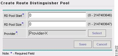
Step 4
The Create Route Distinguisher Pool window appears, as shown in Figure 2-52.
Figure 2-52 Create Route Distinguisher Pool
Step 5
Step 6
Step 7
The Select Provider window appears (not shown).
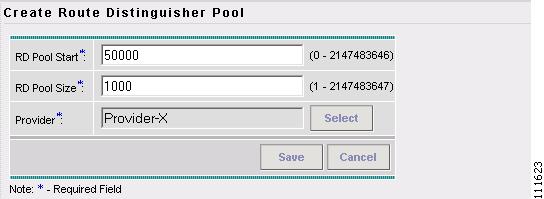
Step 8
The Create Route Distinguisher Pool window appears, as shown in Figure 2-53.
Figure 2-53 Create Route Distinguisher Pool
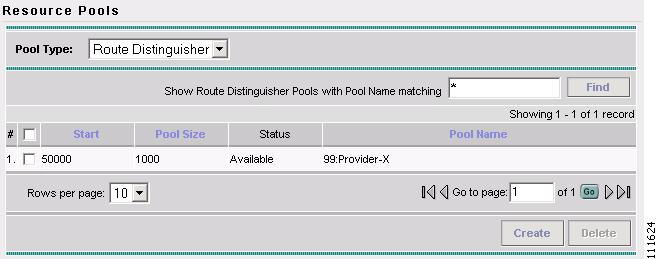
Step 9
The Resource Pools - Route Distinguisher window appears, as shown in Figure 2-15.
Figure 2-54 Create Route Distinguisher Pool
You have saved a Route Distinguisher Pool in the Repository.
Create a Route Target Pool
This section describes how to create a Route Target Pool with the ISC GUI.
To create a Route Target Pool with the ISC GUI, follow these steps:
Step 1
Step 2
The Resource Pools window appears (not shown).
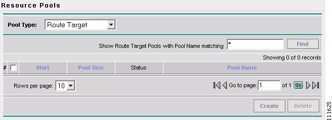
Step 3
The Resource Pools - Route Target window appears, as shown in Figure 2-55.
Figure 2-55 Create Route Target Pool
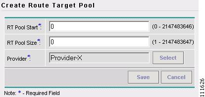
Step 4
The Create Route Target Pool window appears, as shown in Figure 2-56.
Figure 2-56 Create Route Target Pool
Step 5
Step 6
Step 7
The Select Provider window appears (not shown).
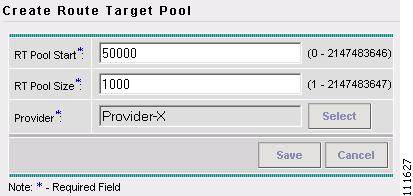
Step 8
The Create Route Target Pool window appears, as shown in Figure 2-57.
Figure 2-57 Create Route Target Pool
Step 9
The Resource Pools - Route Target window appears, as shown in Figure 2-58.
Figure 2-58 Resource Pools - Route Target
You have saved a Route Target Pool in the Repository.
Create a Site of Origin Pool
This section describes how to create a Site of Origin Pool with the ISC GUI.
To create a Site of Origin Pool with the ISC GUI, follow these steps:
Step 1
Step 2
The Resource Pools window appears (not shown).
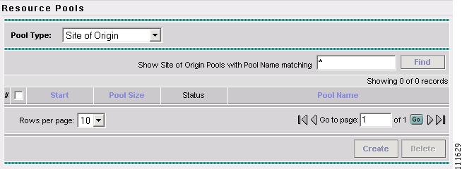
Step 3
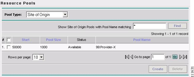
The Resource Pools - Site of Origin window appears, as shown in Figure 2-59.
Figure 2-59 Resource Pools - Site of Origin
Step 4
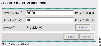
The Create Site of Origin Pool window appears, as shown in Figure 2-60.
Figure 2-60 Create Site of Origin Pool
Step 5
Step 6
Step 7
The Select Provider window appears (not shown).
Step 8
The Create Route Target Pool window appears, as shown in Figure 2-61.
Figure 2-61 Resource Pools - Site of Origin
You have saved a Site of Origin Pool in the Repository.
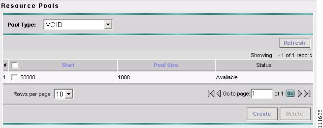
Create a VC ID Pool
This section describes how to create a Virtual Circuit ID (VC ID) Pool with the ISC GUI.
To create a VC ID Pool with the ISC GUI, follow these steps:
Step 1
Step 2
The Resource Pools window appears (not shown).
Step 3
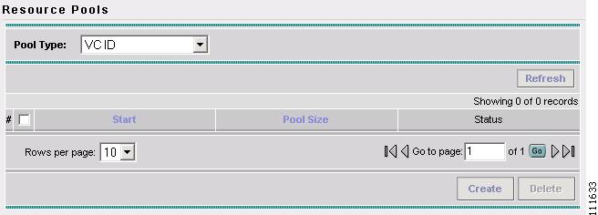
The Resource Pools - VC ID window appears, as shown in Figure 2-62.
Figure 2-62 Resource Pools - VC ID
Step 4
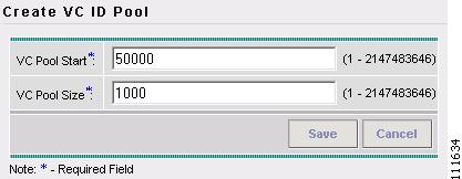
The Create VC ID Pool window appears, as shown in Figure 2-63.
Figure 2-63 Create VC ID Pool
Step 5
Step 6
Step 7
The Resource Pools - VC ID window appears, as shown in Figure 2-64.
Figure 2-64 Resource Pools - VC ID
You have saved a VC ID Pool in the Repository.
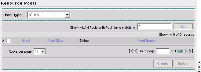
Create a VLAN Pool
This section describes how to create a VLAN (VC ID) Pool with the ISC GUI.
To create a VLAN Pool with the ISC GUI, follow these steps:
Step 1
Step 2
The Resource Pools window appears (not shown).
Step 3
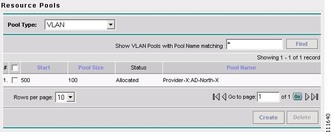
The Resource Pools - VLAN window appears, as shown in Figure 2-65.
Figure 2-65 Resource Pools - VLAN
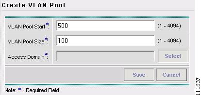
Step 4
The Create VLAN Pool window appears, as shown in Figure 2-66.
Figure 2-66 Select Device
Step 5
Step 6
Step 7
The Select Access Domain window appears, as shown in Figure 2-67.
Figure 2-67 Select Access Domain
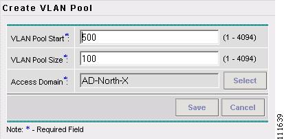
Step 8
Step 9
The Create VLAN Pool window appears, as shown in Figure 2-68.
Figure 2-68 Create VLAN Pool
Step 10
The Resource Pools - VLAN window appears, as shown in Figure 2-69.
Figure 2-69 Resource Pools - VLAN
You have saved a VLAN Pool in the Repository.
Defining a VPN
During service deployment, ISC generates the Cisco IOS commands to configure the logical VPN relationships.
At the beginning of the provisioning process, before creating a Service Policy, a VPN must be defined within ISC. The first element in a VPN definition is the name of the VPN.
To create a VPN Name, follow these steps:
Step 1
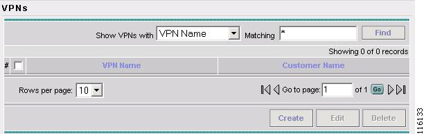
Step 2
The VPN window appears, as shown in Figure 2-70.
Figure 2-70 VPNs
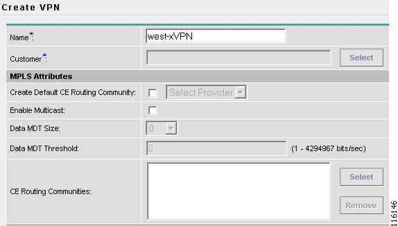
Step 3
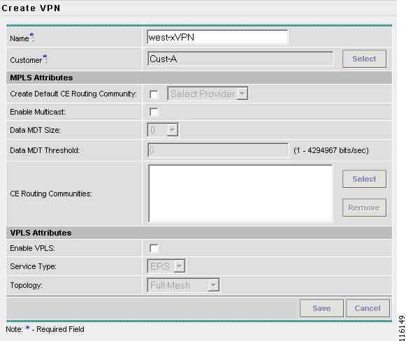
The Create VPN window appears, as shown in Figure 2-71.
Figure 2-71 Create VPN
Step 4
Step 5
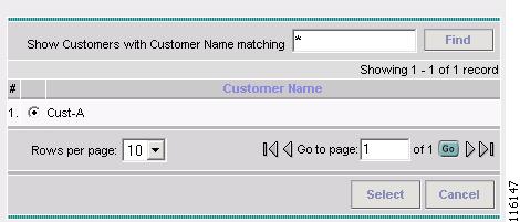
The Select Customer window appears, as shown in Figure 2-72.
Figure 2-72 Select Customer
Step 6
Step 7
The VPNs window reappears, as shown in Figure 2-73.
Figure 2-73 VPNs
Step 8
•
•
Step 9
The VPN Name (west-xVPN) is associated with the Customer (Cust-A) in this new VPN definition.
Defining an MVRFCE PE-CE Service Policy
To define an MVRFCE PE-CE Service Policy, follow these steps:
Step 1
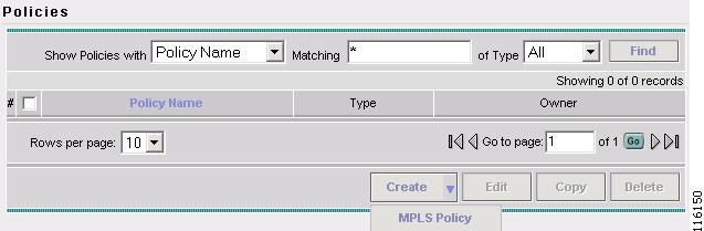
Step 2
The Policies window appears, as shown in Figure 2-74.
Figure 2-74 Policies
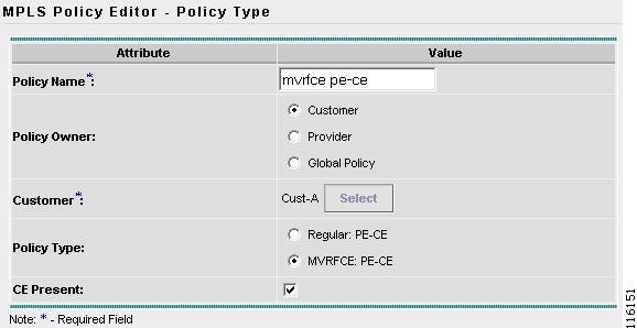
Step 3
The MPLS Policy Editor - Policy Type window appears, as shown in Figure 2-75.
Figure 2-75 MPLS Policy Editor - Policy Type
Step 4
Step 5
Step 6
Step 7
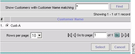
Step 8
The Customer for MPLS Policy ownership window appears, as shown in Figure 2-76.
Figure 2-76 Customer for MPLS Policy
Step 9
Step 10
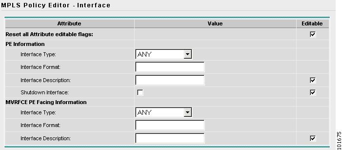
The MPLS Policy Editor - PE Interface window appears, as shown in Figure 2-77.
Figure 2-77 The MPLS Policy Editor - PE Interface
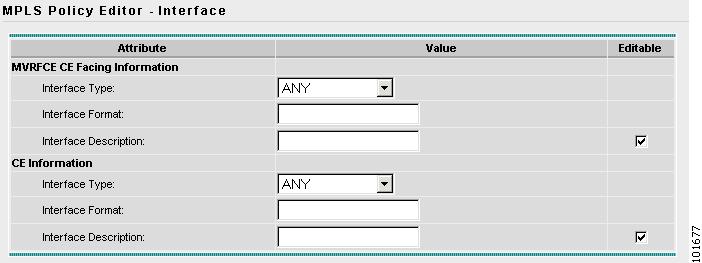
Step 11
The MPLS Policy Editor - CE Interface window appears, as shown in Figure 2-78.
Figure 2-78 The MPLS Policy Editor - CE Interface
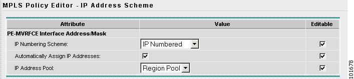
Step 12
Note
The MPLS Policy Editor - PE IP Address Scheme window appears, as shown in Figure 2-79.
Figure 2-79 The MPLS Policy Editor - PE IP Address Scheme
Step 13
The IP Address Pool appears with the Region Pool in the window.
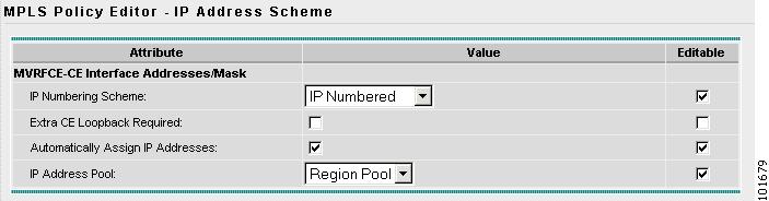
Step 14
The MPLS Policy Editor - CE IP Address Scheme window appears, as shown in Figure 2-79.
Figure 2-80 The MPLS Policy Editor - CE IP Address Scheme
Step 15
Step 16
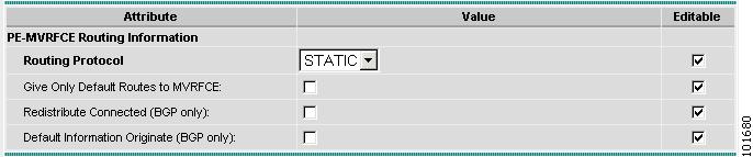
The MPLS Policy Editor - PE Routing Information window appears, as shown in Figure 2-81.
Figure 2-81 The MPLS Policy Editor - PE Routing Information
Step 17
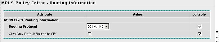
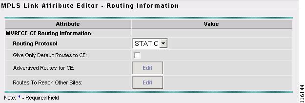
The MPLS Policy Editor - CE Routing Information window appears, as shown in Figure 2-82.
Figure 2-82 The MPLS Policy Editor - CE Routing Information
Step 18
Note
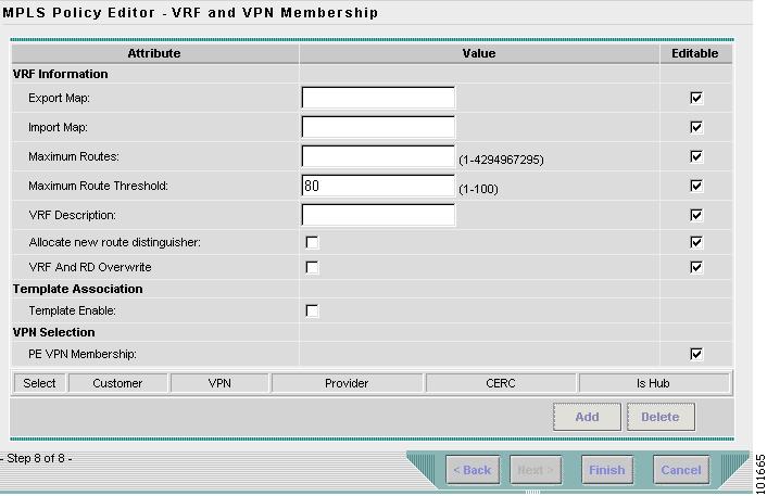
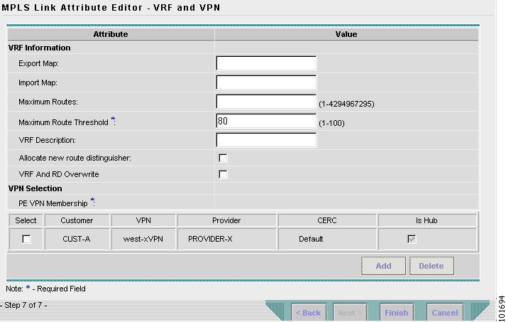
The MPLS Policy Editor - VRF and VPN Membership window appears, as shown in Figure 2-83.
Figure 2-83 The MPLS Policy Editor - VRF and VPN Membership
Step 19
Note
Step 20
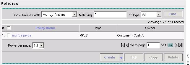
The Policies window reappears, as shown in Figure 2-84.
Figure 2-84 Policies
The MVRFCE PE-CE Service Policy is complete.
Creating an MVRFCE PE-CE Service Request
To create a MVRFCE PE-CE Service Request, follow these steps:
Step 1
Step 2
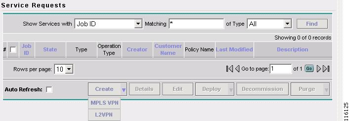
The Service Requests window appears, as shown in Figure 2-85.
Figure 2-85 Service Requests
Step 3
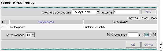
The Select MPLS Policy window appears, as shown in Figure 2-86.
Figure 2-86 Select MPLS Policy
Step 4
Step 5
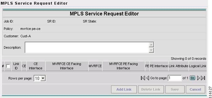
The MPLS Service Request Editor window appears, as shown in Figure 2-87.
Figure 2-87 MPLS Service Request Editor
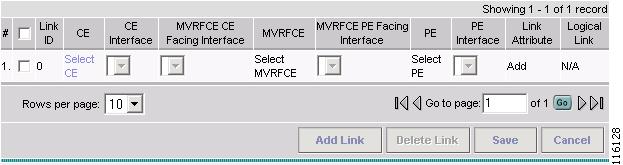
Step 6
The MPLS Service Request Editor window appears, as shown in Figure 2-88.
Figure 2-88 MPLS Service Request Editor - Select CE
Step 7
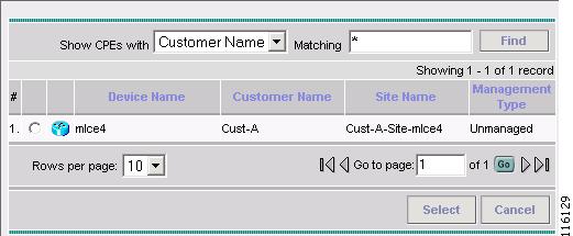
The Select CPE Device - CE window appears, as shown in Figure 2-89.
Figure 2-89 Select CPE Device - CE
Step 8
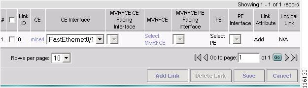
The MPLS Service Request Editor window appears, as shown in Figure 2-90.
Figure 2-90 MPLS Service Request Editor - CE Interface
Step 9
Step 10
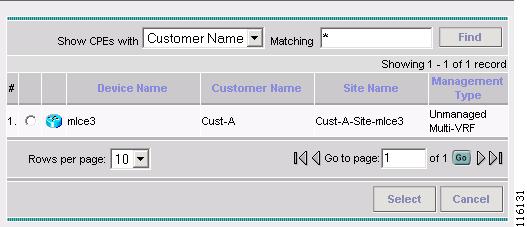
The Select CPE Device - MVRFCE window appears, as shown in Figure 2-91.
Figure 2-91 Select CPE Device - MVRFCE
Step 11
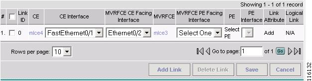
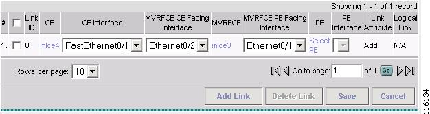
The MPLS Service Request Editor window appears, as shown in Figure 2-92.
Figure 2-92 MPLS Service Request Editor - MVRFCE CE Facing Interface
Step 12
Step 13
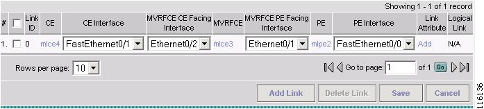
The MPLS Service Request Editor window appears, as shown in Figure 2-93.
Figure 2-93 MPLS Service Request Editor - Select MVRFCE PE Facing Interface
Step 14
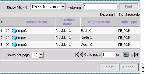
The Select PE Device window appears, as shown in Figure 2-94.
Figure 2-94 Select PE Device
Step 15
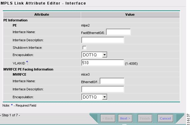
The MPLS Link Attribute Editor window appears, as shown in Figure 2-95.
Figure 2-95 MPLS Link Attribute Editor - Interface
Step 16
Step 17
The MPLS Link Attribute Editor - Interface window appears, as shown in Figure 2-95.
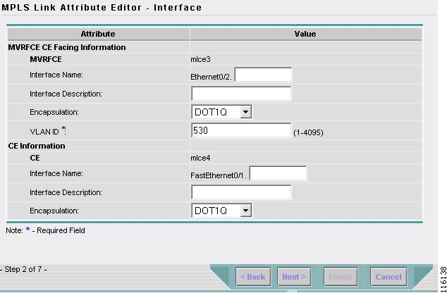
Figure 2-96 MPLS Link Attribute Editor - Interface
Step 18
Step 19
The MPLS Link Attribute Editor - Interface window appears, as shown in Figure 2-97.
Figure 2-97 MPLS Link Attribute Editor - Interface
Step 20
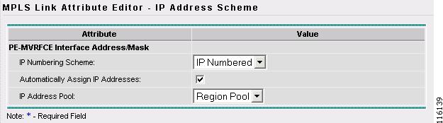
Click Next.
The MPLS Link Attribute Editor - IP Address Scheme window appears, as shown in Figure 2-98.
Figure 2-98 MPLS Link Attribute Editor - IP Address Scheme
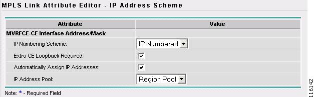
Step 21
The MPLS Link Attribute Editor - IP Address Scheme window appears, as shown in Figure 2-99.
Figure 2-99 MPLS Link Attribute Editor - IP Address Scheme
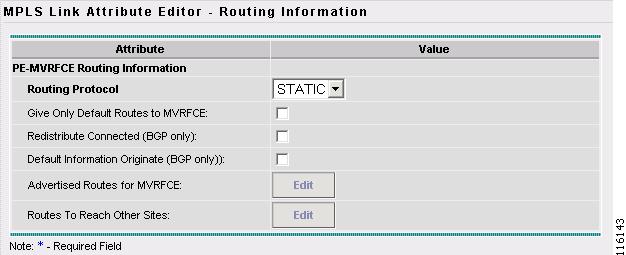
Step 22
The MPLS Link Attribute Editor - Routing Information window reappears, as shown in Figure 2-100.
Figure 2-100 MPLS Link Attribute Editor - PE Routing Information
Step 23
The MPLS Link Attribute Editor - Routing Information window reappears, as shown in Figure 2-101.
Figure 2-101 MPLS Link Attribute Editor - MVRFCE Routing Information
Step 24
The MPLS Link Attribute Editor - VRF and VPN window appears (not shown).
Step 25
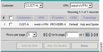
The Select VPN window appears, as shown in Figure 2-102.
Figure 2-102 Select VPN
Step 26
Step 27
Step 28
The MPLS Link Attribute Editor - VRF and VPN window reappears, as shown in Figure 2-103.
Figure 2-103 MPLS Service Request Editor
Step 29
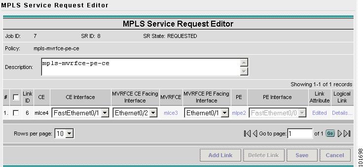
The MPLS Service Request Editor window appears, as shown in Figure 2-104.
Figure 2-104 MPLS Service Request Editor
Step 30
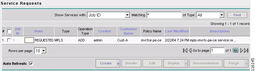
The MPLS Service Requests window appears, as shown in Figure 2-105.
Figure 2-105 Service Request
The MPLS VPN MVRFCE PE-CE Service Request is in the Requested state and ready to deploy.