-
Cisco IP Solution Center MPLS VPN User Guide, 4.0
-
Index
-
About This Guide
-
IP Solution Center - MPLS VPN
-
Provisioning an Unmanaged Multi-VRF CE
-
MPLS VPN Service Policies
-
MPLS VPN Service Requests
-
Provisioning Regular PE-CE Links
-
Provisioning MVRFCE PE-CE Links
-
Provisioning Management VPN
-
Provisioning Cable Services
-
Provisioning Carrier Supporting Carrier
-
Spanning Multiple Autonomous Systems
-
Setting Up the Network
-
Service Request Transition States
-
Troubleshooting MPLS VPN
-
 Feedback
Table Of Contents
Tasks to Be Completed Before Using ISC Software
Configuring Devices in the ISC MPLS Environment
Setting Up the Secure Shell (SSH) on Edge Routers
Setting Up SNMPv1 and SNMPv2 on the Routers in the Service Provider Network
Setting the SNMPv3 Parameters on the Routers in the Service Provider Network
Enabling SA Agent on Edge Routers for SLA Jitter Probes
Enabling Telnet Sessions for Terminal Server Ports
Setting Up the ISC Workstation
Setting the ISC Host as a TFTP Server
Defining Collection Zones and Assigning Devices to Zones
Assigning Devices to a Collection Zone
Seeing the Devices Assigned to a Collection Zone
Setting Up the Network
The Cisco IP Solution Center (ISC) MPLS VPN Management feature is an MPLS VPN provisioning and auditing tool. It focuses on the provider edge routers (PEs), customer edge routers (CEs), and the link between them. ISC can use either a Telnet gateway or Cisco Configuration Center software to transport configuration file information to and from target routers. Additional features include Class of Service (CoS) provisioning, VPN-aware NetFlow traffic profiling, and Service Level Agreement (SLA) monitoring.
ISC also provides external access to its provisioning, traffic profiling, and SLA monitoring features through CORBA/XML APIs.
In an MPLS network, a customer edge router (CE) is connected to a provider edge router (PE) in such a way that the customer's traffic is encapsulated and transparently sent to other CEs, thus creating a virtual private network. The Cisco ISC provisioning engine for MPLS accesses the configuration files on both the CE and PE to compute the necessary changes to the configuration files to support the service on the PE-CE link.
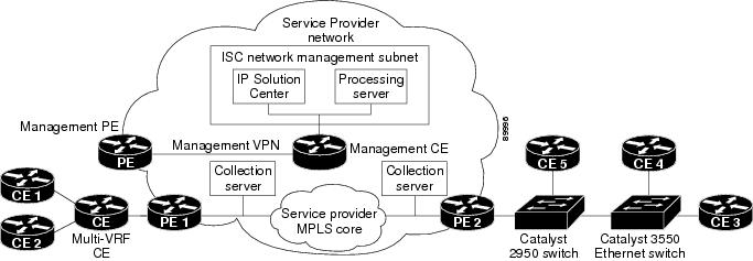
As shown in Figure A-1, Cisco requires that the Cisco ISC software is installed on its own dedicated system. The Cisco ISC workstation is optionally connected on a LAN to one or more Processing servers and Collection servers.
Figure A-1 Cisco ISC: MPLS VPN Management in the Service Provider Network
The principal Cisco ISC network elements are as follows:
•
ISC Network Management Subnet
The ISC Network Management Subnet is required when the service provider's service offering entails the management of CEs. The management subnet consists of the IP Solution Center workstation where ISC is installed on a Sun Solaris 8 system. On the same LAN, the service provider can optionally install one or more Processing servers.
The Processing servers are responsible for executing tasks such as provisioning, auditing, SLA data collection, and so on. There can be one or more Processing server machines.
•
The Management VPN is a special VPN employed by the ISC Network Management Subnet to manage the CEs in a service provider network. Once a CE is in a VPN, it is no longer accessible by means of conventional IPv4 routing, unless the CEs are part of the Management VPN. To communicate with the PEs, the link between the Management PE (MPE) and the Management-CE (MCE) uses a parallel IPv4 link. The Management VPN connects to the managed CEs.
•
The Multi-VRF CE is a feature that provides for Layer 3 aggregation. Multiple CEs can connect to a single Multi-VRF CE (typically in an enterprise network); then the Multi-VRF CE connects directly to a PE. Figure A-1 shows CE 1 and CE2 connected to the Multi-VRF CE, and the Multi-VRF CE is connected directly to the PE. For details, see Multi-VRF CE.
•
The service provider can install multiple Layer 2 switches between a PE and CE, as shown in Figure A-1. This feature provides Layer 2 aggregation. Additional CEs can be connected to the switches as well. Cisco supports two switches for the Layer 2 access to MPLS: either a Cisco Catalyst 2950 Switch or a Cisco Catalyst 3550 Intelligent Ethernet Switch.
•
Cisco ISC is designed to provision a large number of devices through its distributed architecture. If the Master server (equivalent to the ISC workstation) cannot keep up with the number of devices, Collection servers can be added to off load the work of the Master server. Among other tasks, Collection servers are responsible for uploading and downloading configuration files to and from Cisco routers. For more information, see Defining Collection Zones and Assigning Devices to Zones.
Tasks to Be Completed Before Using ISC Software
Before you use Cisco ISC: MPLS VPN Management software to provision an MPLS network, the Service Provider must complete the following tasks:
1.
2.
3.
4.
5.
6.
7.
8.
9.
Cautionulimit -n <number>"), comment out this command line in the file.
Cisco ISC cannot override the file descriptor limitation setting in the login shell file. If the value is set incorrectly, Cisco ISC may experience operational problems.
Configuring Devices in the ISC MPLS Environment
This section describes the tasks the Service Provider should complete to set up devices in the Cisco IP Solution Center MPLS environment.
Setting Up the Secure Shell (SSH) on Edge Routers
Service providers need a mechanism to deploy VPN configuration files to remote edge routers in a secure manner. The basic requirements for secured management are as follows:
•
•
Cisco ISC uses TGS as the configuration file download mechanism. One of the modes that TGS can operate in is Secure Shell (SSH) mode. The Telnet Gateway Server uses SSH for both authentication and encryption. In this scheme, the edge device router functions as an SSH server, while Cisco ISC functions as the SSH client.
Note
The procedure for configuring SSH on edge device routers is as follows:
Setting Up SNMPv1 and SNMPv2 on the Routers in the Service Provider Network
The Simple Network Management Protocol (SNMP) must be configured on each router and edge device in the service provider network. To determine whether SNMP is enabled and to set the SNMP community strings on a router, execute the following steps for each router.
Tip
Setting the SNMPv3 Parameters on the Routers in the Service Provider Network
Simple Network Management Protocol Version 3 (SNMPv3) is an interoperable standards-based protocol for network management. SNMPv3 provides secure access to devices by a combination of authenticating and encrypting packets over the network.
This section describes how to set the SNMPv3 parameters on the routers in the service provider network. To complete the task regarding SNMPv3 parameters, you also must set a selected set of parameters in the Cisco ISC software. The SNMPv3 parameters you set on the routers must match the SNMPv3 parameters you specify in the Cisco ISC software.
The security features provided in SNMPv3 are as follows:
•
•
•
Using SNMPv3, data can be collected securely from SNMP devices without fear of the data being tampered with or corrupted. Also, using the SNMP Set command, packets that change a router's configuration can be encrypted to prevent its contents from being exposed on the network.
SNMPv3 provides for both security models and security levels. A security model is an authentication strategy that is set up for a user and the group in which the user resides. A security level is the permitted level of security within a security model. A combination of a security model and a security level determines which security mechanism is employed when handling an SNMP packet.
Three security models are available: SNMPv1, SNMPv2c, and SNMPv3.
Table A-1 identifies the combinations of security models and levels.
SNMPv3 objects have the following characteristics:
•
•
•
•
•
To check the existing SNMP configuration, use these commands:
•
•
To set the SNMPv3 server group and server users parameters on a router, execute the following steps:
Enabling SA Agent on Edge Routers for SLA Jitter Probes
If you want to use the (voice) jitter protocol to collect SLA data from the edge devices in your network, you must enable SA Agent on each device from which you want to collect this data.
This procedure assumes that you have already enabled SNMP and set the SNMP parameters on the edge device router, as described in the previous sections of this chapter.
To enable SA Agent on an edge router for jitter probes, execute the following steps:
Enabling Telnet Sessions for Terminal Server Ports
You must enable at least as many Telnet sessions on the terminal server as there are terminal server ports. Otherwise, concurrent access to all the routers via the terminal server may fail.
To enable the appropriate number of Telnet sessions for terminal server access, follow these steps:
Time Zone Support in ISC
ISC supports only the time zones that are in the /usr/share/lib/zoneinfo directory of the Solaris workstation on which the ISC software is installed. The contents of this directory could change with each version of Solaris.
ISC cannot change the manner in which these time zones are configured, most notably the variations in Daylight Savings Time.
Note
Setting Up the ISC Workstation
This section describes the elements or components you should set up on the Cisco ISC workstation.
Enabling TFTP in Cisco ISC
The Cisco ISC software in MPLS mode is set by default to use Telnet as the mechanism to transport configuration files to and from routers. To set Cisco ISC software to use the Trivial File Transfer Protocol (TFTP) instead, edit the Hosts Configuration GTL device-config-access protocol property as described in this section. ISC properties are defined in the Dynamic Component Properties Library (DCPL).
Changing this value sets the default upload and download mechanism for all the devices configured to use the default for the Terminal Session Protocol and the Configuration Access Protocol.
Step 1
Step 2
Step 3
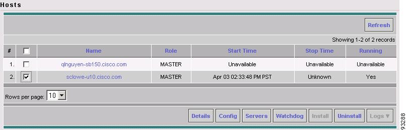
The Hosts window appears (see Figure A-2).
Figure A-2 Selecting the ISC Host
The Hosts window lists the hosts and servers that are managed by ISC.
Step 4
Step 5
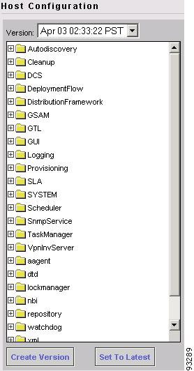
The Hosts Configuration window appears (see Figure A-3).
Figure A-3 Hosts Configuration Window
Step 6
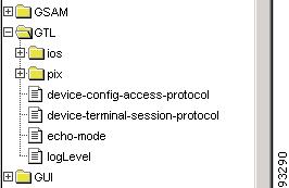
Figure A-4 shows the expanded GTL folder displaying the list of GTL options.
Figure A-4 GTL Options
Step 7
The GTL Attributes dialog box for the device access protocol appears (see Figure A-5).
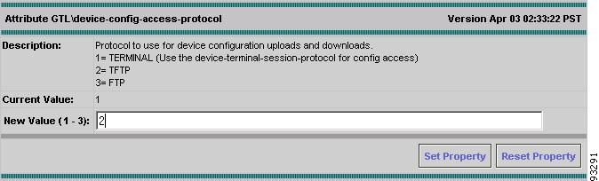
Figure A-5 Specifying the Device Access Protocol
As you can see from the Description area, the numeral 2 corresponds to TFTP.
Step 8
Step 9
Proceed to the next section to define the ISC workstation as a TFTP server.
Setting the ISC Host as a TFTP Server
This section describes how to set up a local Solaris host as a TFTP server. If the ISC Network Management Subnet includes one or more Collection or Processing servers, you must set up the Cisco ISC workstation as a TFTP host.
To set up the ISC workstation as a TFTP server:
Step 1
Step 2
The Hosts window appears (see Figure A-2).
Step 3
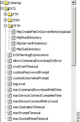
Figure A-6 shows the expanded DCS folder displaying the list of TFTP options.
Figure A-6 TFTP Options
Step 4
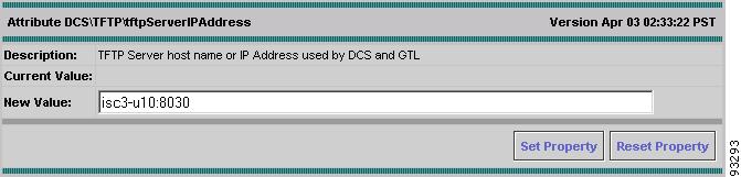
The TFTP Server IP Address Attributes dialog box appears (see Figure A-7).
Figure A-7 Specifying the Host as a TFTP Server
Step 5
Step 6
Step 7
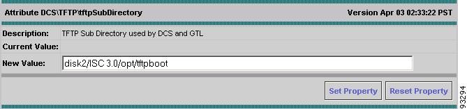
The TFTP Subdirectory dialog box appears (see Figure A-8).
Figure A-8 Specifying the Directory for the TFTP Server
Step 8
Step 9
Step 10
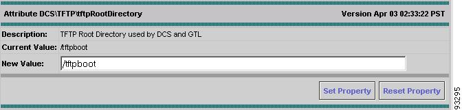
The TFTP Root Directory dialog box appears (see Figure A-9).
Figure A-9 Specifying the TFTP Root Directory
Step 11
Step 12
Step 13
Step 14
Step 15
Defining Collection Zones and Assigning Devices to Zones
ISC is designed to provision a large number of devices through its distributed architecture. If the Master server (equivalent to the ISC workstation) cannot keep up with the number of devices, Collection servers can be added to off load the work of the Master server.
Since Collection servers communicate a great deal with the network devices (for example, uploading and downloading configuration files to Cisco routers is handled through a Collection server), it makes sense to place Collection servers in a LAN near the routers, instead of placing the Collection server in the ISC network management subnet of the Master server.
Network devices are associated with collection servers by means of collection zones. A collection zone is a geographical grouping of devices that are served by a single Collection server. Each collection zone is associated with exactly one Collection server that collects data from each device. However, a Collection server can service multiple collection zones. For example, you may initially create several collection zones and have all of them serviced by the Master server. As the number of devices in each zone grows you can install additional Collection servers and assign some of the zones to them.
For information on installing a Collection server in ISC, see "Installing ISC" in Chapter 2, "Installing and Logging Into ISC" in the Cisco IP Solution Center Installation Guide.
The recommended sequence for setting up collection zones in ISC is as follows:
1.
2.
3.
4.
Defining Collection Zones
To define collection zones in ISC, follow these steps:
Step 1
Step 2
Step 3
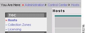
The Hosts dialog box appears, along with the Hosts table of contents (TOC), as shown in Figure A-10.
Figure A-10 Collection Zones Option in Hosts TOC
Step 4
The Collection Zones dialog box is displayed.
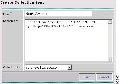
Step 5
The Create Collection Zone dialog box appears (see Figure A-11).
Figure A-11 Creating a Collection Zone
Step 6
Step 7
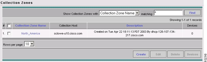
You return to the Collection Zones dialog box, where the new collection zone name and its attributes are displayed (see Figure A-12).
Figure A-12 Collection Zone Created
Step 8
Assigning Devices to a Collection Zone
After you have defined all the collection zones that are necessary for your network, you must assign the set of geographically related network devices to the appropriate collection zone.
To assign devices to a collection zone:
Step 1
Step 2
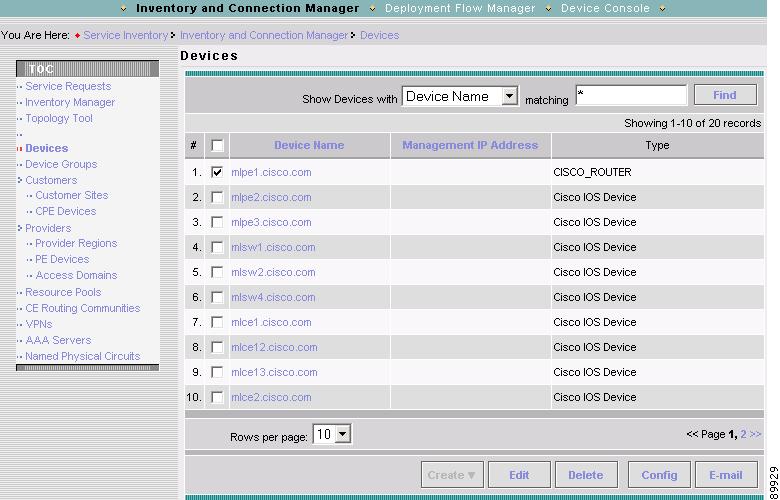
The Devices dialog box appears (see Figure A-13).
Figure A-13 List of Devices Recognized by ISC
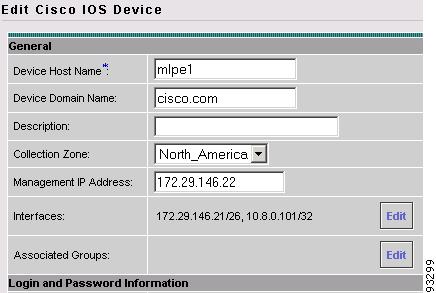
Step 3
The Edit Cisco IOS Devices dialog box appears (see Figure A-14).
Figure A-14 Specifying the Collection Zone for a Device
Step 4
Step 5
Seeing the Devices Assigned to a Collection Zone
To see the list of network devices assigned to a specific collection zone:
Step 1
The Hosts dialog box appears, along with the Hosts table of contents (TOC), as shown in Figure A-10.
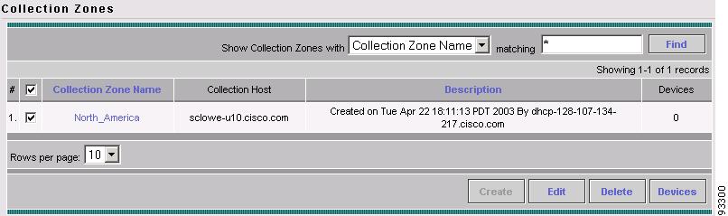
Step 2
The Collection Zones dialog box is displayed (Figure A-15).
Figure A-15 Selecting the Collection Zone
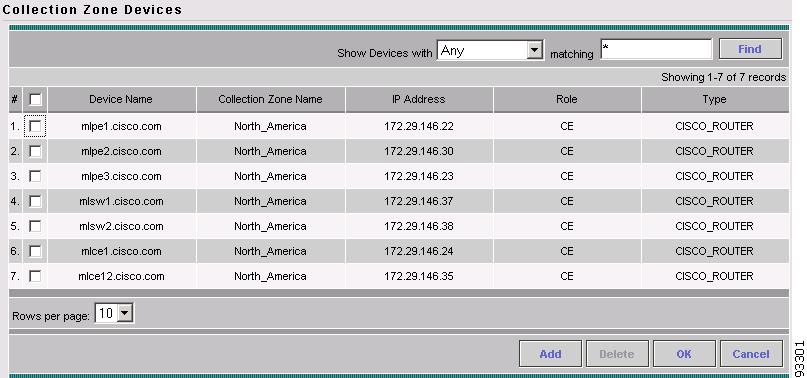
Step 3
ISC displays the list of devices assigned to the specified collection zone (see Figure A-16).
Figure A-16 List of Devices in a Collection Zone