-
Cisco Active Network Abstraction NetworkVision User Guide, 3.6
-
Cisco ANA Client Overview
-
Getting Started
-
Working with Cisco ANA NetworkVision Tables
-
Working with Cisco ANA NetworkVision Maps
-
Viewing Device Properties
-
Viewing Network Device Inventory
-
Working with Links
-
Working with Tickets
-
Working with Cisco ANA PathTracer
-
Working with Business Tags
-
Icon Reference
-
 Feedback
Table Of Contents
Working with Cisco ANA NetworkVision Maps
Removing a Device from the Map
Filtering Links According To Type
Working with Cisco ANA NetworkVision Maps
This chapter describes how to work with the topological maps displayed in the workspace of the Cisco ANA NetworkVision window. The topological map is the main tool used by Cisco ANA NetworkVision to display the links and relationships between the network elements and/or aggregated nodes.
•
Opening Selected Maps, describes how to open maps that were last visited by you, quickly and easily when the application is launched.
•
•
•
•
•
•
•
•
•
•
•
•
•
•
•
•
•
•
•
•
•
•
•
•
•
•
Opening Selected Maps
When Cisco ANA NetworkVision is launched, the Cisco ANA NetworkVision window appears. Maps that were last visited by you can be opened quickly when the application is launched, if you closed the application without closing the maps.
Note
To open a selected map:
Step 1
The Open Selected Maps dialog box displays a list of the maps last visited by you and that were not closed by you when exiting the application. By default all the maps that were last visited by you are selected.
The following buttons are displayed in the Open Selected Maps dialog box:
•
•
•
Step 2
or
Click None,
or
Clear the checkbox(es) for the maps that you do not want to display in the Cisco ANA NetworkVision window and click Selected.
The maps are displayed in the Cisco ANA NetworkVision window according to the defined selection.
Note
Creating a New Map
When Cisco ANA NetworkVision is launched for the first time, or if None is selected in the Open Selected Maps dialog box (as described in the previous section) the Cisco ANA NetworkVision window appears empty.
A new map must be created, or a map that was previously saved can be opened, in order to display the network. Cisco ANA NetworkVision supports the creation of multiple network maps in order to represent specific network views. Views can cover specific network segments, customer networks, or any other mix of network elements desired. When a user creates a map it is available to other users (assuming they have sufficient access/security privileges).
The network maps provide a graphic display of active faults and alarms and serve as an easy access point for the activation of services.
Note
Note
To create a new map:
Step 1
or
Select New Map from the File menu. The Create Map dialog box is displayed.
Note
The minimum map name length of is 1 character.
The maximum map name length is 65 characters.
The map name cannot contain any symbols, excluding the $ symbol.The Advanced button enables you to filter the links displayed in the map pane. For more information see Filtering Links According To Type.
Step 2
Opening a Map
Cisco ANA NetworkVision enables you to open a map that was previously saved. When you open the map, the network information is automatically refreshed. For example, if a device was up the last time that the map was saved and closed, and then the device is moved to maintenance, the next time you open the map the management status of the device will be updated accordingly and the device will display a maintenance status.
Note
see Opening Selected Maps.To open a map:
Step 1
or
Select Open from the File menu. The Map List dialog box is displayed.
The Map List dialog box displays the map name as defined by the network administrator.
The Find field enables you to search for information in the table according to the selected column. For more information see Finding Text in a Table.
The Map List dialog box contains the following tools:
Export to CSV—Exports the information displayed in the table. For more information see Exporting the Table to a File.
Note
Delete Map—Deletes the selected map from the Map List dialog box, the Cisco ANA NetworkVision window and from the database. If a map that is being opened is deleted, this map will close. For more information see Deleting a Map.
Rename Map—Renames the selected map in the Map List dialog box and Cisco ANA NetworkVision window. For more information see Renaming a Map.
Sort Table Values—Enables you to sort the information displayed in the table.
Filter—Defines a filter for the information displayed in the table. For more information see Defining a Filter.
Note
Set Selection Filter—Applies filters to the selected line or lines displayed in the Map List.
Note
Previous Selection Filter—Enables you to undo the last applied filter selection.
Rewind All—Enables you to undo previous filter selections, and display all the original information in the table.
Help—Opens the online help.
Step 2
or
Right-click on the required map, and select Open from the displayed shortcut menu,
or
Double-click on the required map. The map is displayed in the Cisco ANA NetworkVision window with the network.
One or more maps can be opened in the Cisco ANA NetworkVision window displaying the various available networks. Use the Windows menu to move between the open maps. For more information on the Cisco ANA NetworkVision window, see "Getting Started".
Note
Adding a Device
Cisco ANA NetworkVision enables you to add devices to the network. The device is added to the map or aggregation selected in the tree pane and workspace. In addition, devices that are added to the network are automatically saved.
Note
To add a device:
Step 1
or
Select Add Device from the File menu. The Device List dialog box is displayed, with all the devices that are managed by the system.
Note
For more information about:
•
•
Step 2
Note
Step 3
Note
Step 4
Removing a Device from the Map
Cisco ANA NetworkVision enables you to remove a device or aggregated node from the map.
A device that has been removed from the map is not deleted from the network.
To remove a device or aggregated node from the map:
Step 1
Step 2
Defining the Map Layout
Cisco ANA NetworkVision enables you to select the way in which the network object topology is displayed. The map pane displays the selected layout, namely, Circular, Symmetric, Hierarchical or Tree.
To define the map layout:
Step 1
•
•
•
•
or
Select Layout from the View menu and from the dropdown list, select one of the options displayed, as described above.
The map is displayed according to the selected option.
Note
Saving a Map
Cisco ANA NetworkVision enables you to save map layouts and change existing ones.
The following changes are saved automatically:
•
•
•
The following changes to the workspace are only saved when the Save option is selected:
•
•
•
•
The maps can then be opened later as required.
To save changes to a map:
Step 1
or
Select Save Map from the File menu. Your changes are saved.
Saving as a New Map
The user can save a copy of the entire map or parts thereof (specific devices and aggregations) while leaving the original map intact.
To save as a new map:
Step 1
Step 2
Step 3
or
You can accept the name provided by default.
Step 4
Note
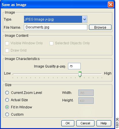
Saving a Map as an Image
Cisco ANA NetworkVision enables you save the currently displayed map as an image.
To save a map as an image:
Step 1
Figure 4-1 Save as Image Dialog Box
The following fields are displayed in the Image area:
•
Note
•
The following checkboxes are displayed in the Image Content area:
•
•
•
The Image Characteristics area enables you to define the quality of the image by entering a figure or by clicking and dragging the slider.
The following radio buttons are displayed in the Size area:
•
•
•
•
Step 2
Step 3
Closing a Map
Cisco ANA NetworkVision enables you to close a map displayed in the map pane whenever required. At the same time other maps can be left open in order to work with them.
To close a map:
Step 1
or
Click
in the upper right-hand corner of the map in the workspace.
If changes have been made to the map, an information message is displayed.
Step 2
Deleting a Map
Cisco ANA NetworkVision enables you to delete a map from all the views in the Cisco ANA NetworkVision window.
To delete a map:
Step 1
or
Select Open from the File menu. The Map List dialog box is displayed.
Step 2
Step 3
Step 4
Step 5
Note
Renaming a Map
Cisco ANA NetworkVision enables you to rename a map that is displayed in the Cisco ANA NetworkVision window. The name change affects all users of the map and the new name is displayed in the Cisco ANA NetworkVision window of all users.
To rename a map:
Step 1
or
Select Open from the File menu. The Map List dialog box is displayed.
Step 2
Step 3
Step 4
Step 5
Step 6
Resizing a Device
Cisco ANA NetworkVision enables you to define the size of selected devices or aggregated nodes in the map pane, according to predefined sizes or according to a percentage of the current size.
Note
To resize a device or aggregated node:
Step 1
Note
Step 2
or
Select Resize from the Edit menu.
or
Right-click on the selected devices and/or aggregated node in the map pane to display the Device shortcut menu. Select Resize.
The Resize Nodes Controller dialog box is displayed.
The following fields are displayed in the Resize Nodes Controller dialog box:
•
•
Step 3
Step 4
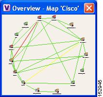
Viewing the Network
Cisco ANA NetworkVision enables you to display the entire network map or any part of the map in the Cisco ANA NetworkVision window.
You can use the Zoom tools or the Overview window to display the part of the map that you require. The Overview window enables you to view all the changes and alarms taking place in the network. In addition, you can display an aggregated node in a thumbnail.
To open an overview of the network:
Step 1
or
Select Overview from the View menu. The Overview window is displayed.
Figure 4-2 Overview Window
Step 2
Step 3
Step 4
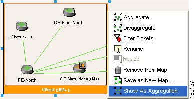
In addition, you can display a thumbnail of the selected aggregated node in the map pane, including all the aggregated devices. Thumbnails can also be nested.
To display a thumbnail of the node:
Step 1
Step 2
Figure 4-3 Thumbnail
Note
Note
Viewing a Network Device
Cisco ANA NetworkVision enables you to view any network device in the currently displayed map.
The network device is selected in the map pane and the tree pane. The ticket pane displays all the active and cleared tickets, however, the user can filter the tickets so that only the tickets of the selected network device are displayed in the ticket pane.
For more information about filtering tickets by device, see Filtering Tickets by Device.
To view a network device:
Step 1
Note
•
Selecting Map Views
Cisco ANA NetworkVision provides you with various selection tools that can be used to view and analyze maps in the map pane.
You can view graphical representations of NEs and various links appearing in the map pane of the Cisco ANA NetworkVision window's workspace using the toolbar buttons.
The Device View and Show Links View buttons open dynamic tables listing network element/device information and respective map context links in table-format (not graphical links). The respective tables are displayed in the Cisco ANA NetworkVision window's workspace. For more information on viewing and working with device view tables and filtering the links view, see "Working with Cisco ANA NetworkVision Tables".
Cisco ANA NetworkVision provides you with various selection tools that can be used to view and analyze maps in the map pane and the links view table displayed in the workspace as described below.
To select a tool:
Step 1
or
On the toolbar, click the required selection tool.
Finding a Ticket Source
Cisco ANA NetworkVision enables you to find the source of a ticket displayed in the ticket pane by highlighting the device in the tree pane and/or map pane.
To find the ticket source:
Step 1
Step 2
Note
Step 3
Finding a Link Source
Cisco ANA NetworkVision enables you to find a link displayed in the links view by highlighting the link in the map pane.
To find the link:
Step 1
Step 2
The source of the link is highlighted in the map pane.
or
If there are two or more lines that represent the same links, for example, a VRF link, the Select Link Context dialog box is displayed. Select the required link context from the dropdown list and click OK. The source of the link is highlighted in the map pane.
Note
Step 3
Finding a Network Device
Cisco ANA NetworkVision enables you to find a device in the map by entering the device name or the device IP address or any part thereof.
To find a device in the map:
Step 1
or
Select Find in Map from the Edit menu. The Find in Map dialog box is displayed.
The Search all map levels checkbox enables you to search for a device or IP address at all levels of the map. This option is selected by default. Clearing this option searches for the device, but excludes device aggregations from the search.
Step 2
Note
Step 3
Step 4
Aggregating Devices
Cisco ANA NetworkVision enables you to aggregate devices in the map pane.
To aggregate devices:
Step 1
or
Select the required devices in the tree pane or map pane using <Ctrl> or the selection tool.
Step 2
or
Select Aggregate from the Node menu,
or
Right-click on the selected devices in the tree pane or map pane to display the Device menu. Select Aggregate.
The Aggregation dialog box is displayed prompting you to enter a name for the aggregated node.
Step 3
The aggregated node icon changes color according to the alarm severity. For more information about device colors, see Status of Network Objects.
The aggregated node selected in the map pane and tree pane of the Cisco ANA NetworkVision window can be disaggregated.
To disaggregate a node:
Step 1
or
Select the required aggregated node in the map pane.
Note
Step 2
or
Right-click on the aggregated node in the tree pane or map pane to display the Aggregated Node shortcut menu. Select Disaggregate.
An information message is displayed.
Step 3
For more information about resizing an aggregated node, see Resizing a Device.
Renaming an Aggregated Node
Cisco ANA NetworkVision enables you to rename an aggregated node that is displayed in the Cisco ANA NetworkVision window.
The name change affects all users of the map and the new name is displayed in the Cisco ANA NetworkVision window of all users.
To rename an aggregated node:
Step 1
Step 2
Step 3
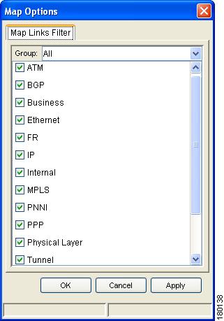
Filtering Links According To Type
The links filter enables the user to filter the links displayed in the map pane and in the links view.
The user quickly selects the types of links to be filtered by selecting from a predefined set of link types in the list or by manually configuring a customized set of link types. The user can either:
•
(method 1)
or•
Note
Note
To filter links according to type (method 1):
Step 1
or
Select New Map from the File menu.
The Create Map dialog box is displayed. For more information see Creating a New Map.
Step 2
Figure 4-4 Map Options Dialog Box
Note
The Map Options dialog box displays a list of all the types of links that can be filtered by the user in the map pane.
The Group dropdown list contains the following options:
•
•
•
•
•
•
ATM, VPN, MPLS, and Ethernet are just some of the options displayed in the Map Options dialog box that can be used to filter the links displayed in the map pane and in the links view.
Note
Step 3
Step 4
Step 5
Step 6
The links are displayed in the map pane and links view according to the defined filter criterion.
A user can also create a map and add the devices with all the links enabled and visible in the map pane and links view. The user can then filter (display or hide) the different types of links required.
To filter links according to type (method 2):
Step 1
Step 2
Step 3
Opening the CPU Usage Graph
Cisco ANA NetworkVision enables you to display memory and CPU usage information for a device/network element, including its history.
To open the CPU usage graph:
Step 1
Step 2
The following areas are displayed in the CPU Usage dialog box:
•
•
•
•
The following tool is displayed in the dialog box:
Exports all the information currently displayed in the dialog box. This information can then be viewed at a later stage. For more information see Exporting the Table to a File.
Step 3
Communicating with Devices
Cisco ANA NetworkVision enables you to communicate with devices in the following ways:
Pinging the Device
Cisco ANA NetworkVision enables you to ping the device in order to check whether the device is responding.
Note
To ping the device:
Step 1
Step 2
Step 3
Telneting the Device
Cisco ANA NetworkVision enables you to communicate with the device using the Telnet window.
Note
To telnet the device:
Step 1
Step 2
Step 3
Step 4
Previewing a Map
Using Cisco ANA NetworkVision you can preview a map before it is printed.
To preview a map:
Step 1
Step 2
The following buttons are displayed in the Print Preview dialog box:
•
•
•
•
•
•
•
Step 3
Defining the Print Setup
Cisco ANA NetworkVision enables you to define the print setup of a map before it is printed.
To define the print setup:
Step 1
Step 2
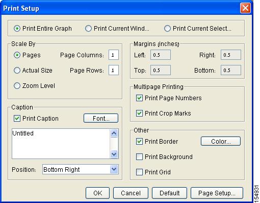
Figure 4-5 Print Setup Dialog Box
The following radio buttons are displayed at the top of the Print Setup dialog box:
•
•
•
The following radio buttons are displayed in the Scale By area, enabling you to define the number of pages and size at which the map is printed:
•
•
•
The following checkbox is displayed in the Caption area:
•
The following field is displayed in the Caption area:
•
The Margins area enables you to define the print margins of the map.
The following checkboxes are displayed in the Multipage Printing area:
•
•
The following checkboxes are displayed in the Other area:
•
•
•
The following buttons are displayed in the Print Setup dialog box:
•
•
Step 3
Step 4
Printing a Map
Cisco ANA NetworkVision enables you to print the map that is currently displayed.
To print a map:
Step 1
or
Click Print in the Print Preview dialog box. For more information about the Print Preview dialog box, see Previewing a Map.