-
Cisco Active Network Abstraction NetworkVision User Guide, 3.6
-
Cisco ANA Client Overview
-
Getting Started
-
Working with Cisco ANA NetworkVision Tables
-
Working with Cisco ANA NetworkVision Maps
-
Viewing Device Properties
-
Viewing Network Device Inventory
-
Working with Links
-
Working with Tickets
-
Working with Cisco ANA PathTracer
-
Working with Business Tags
-
Icon Reference
-
 Feedback
Table Of Contents
Starting Cisco ANA NetworkVision
Cisco ANA NetworkVision Window
Cisco ANA NetworkVision Toolbar
Selecting Cisco ANA NetworkVision Map and Alarm Options
Getting Started
This chapter describes the Cisco ANA NetworkVision working environment and how to access the Cisco ANA NetworkVision tools and commands.
The Cisco ANA NetworkVision window provides access to all Cisco ANA NetworkVision's functionality.
•
Starting Cisco ANA NetworkVision describes how to login to Cisco ANA NetworkVision.
•
•
•
•
•
Starting Cisco ANA NetworkVision
This section provides instructions for launching the Cisco ANA NetworkVision application. Cisco ANA NetworkVision is password protected to ensure security. Before you start working with Cisco ANA NetworkVision make sure you know your username, password and the Cisco ANA Gateway IP address or hostname that you require.
Note
The security level required in order to perform the specific Cisco ANA NetworkVision function is indicated in this User Guide by means of icons.
For more information about the icons used, see Cisco ANA Security.
To start Cisco ANA NetworkVision:
Step 1
or
Click on the Cisco ANA NetworkVision quick launch icon in the taskbar. The Cisco ANA NetworkVision Login dialog box is displayed.
The last four Cisco ANA Gateways to which the user logged in successfully are displayed in the Host dropdown list. The list is displayed in chronological order with the most recent Cisco ANA Gateway displayed at the top of the list.
Step 2
Step 3
or
Select a Cisco ANA Gateway from the Host dropdown list.
Note
Note
Step 4
Note
Note
After logging in to Cisco ANA NetworkVision and launching the application, you may customize Cisco ANA NetworkVision's Options, namely, Start / Display /Audio settings, for example, you can:
•
•
•
For more information on how to customize Cisco ANA NetworkVision's startup and display options, see Selecting Cisco ANA NetworkVision Map and Alarm Options.
Cisco ANA Security
Cisco ANA provides enhanced security when working with and managing the Cisco ANA system. Users are assigned permission levels for an operational scope, which enable them to perform only the functions assigned to the scope and defined security level. A user can be assigned more than one security level.
Permission
The user's ability to perform certain tasks. There are two types of permissions, namely, default and NE related.
•
•
Roles
Cisco ANA implements a security engine that combines a role-based security mechanism that is applied on scopes of network elements granted per user. The system supports user accounts creation, multiple network element scope definition and a set of five pre-defined roles for security and access control to allow different system functions:
This guide uses the icons displayed above (listed in order from lowest to highest security level) to indicate the security level required in order to perform specific Cisco ANA NetworkVision functions.
Note
Each user is assigned a permission level for an operational scope, which enables the user to perform certain tasks. Every user has a private username and password. A user can login from any workstation with the user's own set of permissions and operational scope.
When a user does not have the required permission level to perform a function the appropriate menu option or button is disabled.
The administrator is responsible for defining the types of activities that the user can view and perform using Cisco ANA Manage.
For more information about user security and defining operational scopes, refer to the Cisco Active Network Abstraction Administrator's Guide.
Roles can be granted per scope or at an application level (default permission), namely, all the activities that are related to GUI functionality, not the activities related to devices. The default permission includes:
•
•
•
•
•
Scopes
A scope is a named collection of managed network elements that have been grouped together in order to allow a user to view and/or manage the network elements provided a given role. Grouping can be based on geographical location, network element type (such as DSLAM, router, SW, and so on), network element category (such as access, core, and so on) or any other division according to the network administrator's requirements.
Using NetworkVision, a user that has been assigned a scope can view and/or manage the NEs within this scope according to the role assigned to the user as per the scope. The user cannot view any information regarding NEs that are outside the user's scope, including basic properties, inventory, and alarms.
Cisco ANA NetworkVision Window
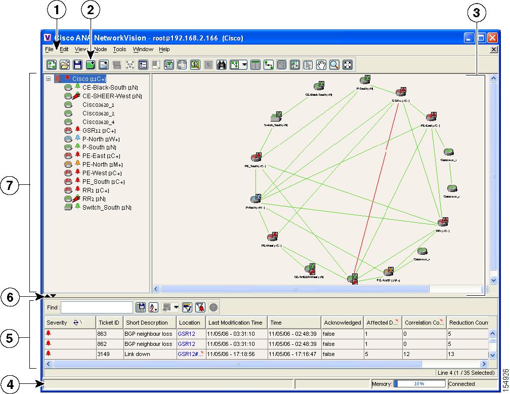
The Cisco ANA NetworkVision window with an open map is displayed below.
Figure 2-1 Cisco ANA NetworkVision Window
The Cisco ANA NetworkVision window is divided into three main areas or panes, as follows:
•
Note
The status bar which is the horizontal area at the bottom of the main Cisco ANA NetworkVision window and other Cisco ANA NetworkVision windows provides information about the current state of what you are viewing in the window relating to the application. There are two states, namely, Connected and Reconnecting. It also displays what is happening to the command that has been sent while the application is waiting for an answer.
In addition, the memory utilization bar in the status bar displays the amount of memory used by the client. By default if memory utilization exceeds 60% it is colored yellow and if it exceeds 80% it is colored red. The default percentage and color values can be configured in the registry.
Dragging the borders of the Cisco ANA NetworkVision window adjusts the size of each pane. The tree pane, and workspace are correlated; this means that selecting an option in the one pane affects the information displayed in the other pane.
Some of the functions that the Cisco ANA NetworkVision window enables you to perform are:
•
•
•
•
•
•
Tree Pane
The tree pane displays a tree-and-branch representation of the network elements and aggregations defined for the loaded map.
The highest level of the tree pane displays the map name, for example, the name of a geographic region, country or a state. When the map name is changed, the Cisco ANA NetworkVision window is updated. The new map name is displayed at the top of the tree pane and in the title bar of the window between brackets.
The lowest level of the tree pane displays a single NE, for example, a router and the device name or the name of the business tag. The tool tip displays the NE name, NE type and IP address. For information about the status of Network Objects, see Status of Network Objects.
Workspace
The workspace enables you to view and modify low-level information. It includes the following areas:
•
•
•
When a user switches between the map pane, device view and links view the following is preserved:
•
•
•
–
–
–
Map Pane
Cisco ANA NetworkVision displays managed network elements in the map pane. In addition, the map pane displays the links or aggregated links and relationships between the network devices, aggregated nodes (topology), and networks on a geographical map.
Each NE is displayed using a NE icon, the color of which reflects severity, as described in the Map Pane. In addition, a management state or alarm icon is displayed together with the IP address. For more information see Appendix A, "Icon Reference". The tool tip displays the NE name, NE type and IP address.
The links or aggregated links that are presented in the map pane:
•
•
Note
The links display tool tips that provide you with information regarding the number of links and partially describe the list of links. Physical links are highlighted in bold.
Note
The map pane enables network objects to be viewed down to the device level. An example of the map pane is displayed in the Cisco ANA NetworkVision Window.
The devices can be moved manually on the geographical map by dragging the required device. In addition, clicking Layout on the toolbar or using the Zoom tools in the menu bar can change the way that the devices are displayed on the map.
Note
Some of the functions that can be performed using the right-click shortcut menu in the map pane are:
•
•
•
•
•
•
•
•
Note
When working with this functionality for MPLS VPN networks, refer to the Cisco Active Network Abstraction Managing MPLS User Guide.
The following icons are used to display the network elements in the Cisco ANA NetworkVision window's tree pane and map panes:
Table 2-2 Device Icons
Unmanaged Network
Network, sub-network or logical aggregation
Router
Generic SNMP
Ethernet Switch
DSLAM
ATM switch
BRAS
Ping VNE
Viewable by a user with a higher permission level
Ghost device
Note
The following colors are used to display the severity (or propagated severity) of a network device when displayed in the map pane, tree pane and ticket pane:
•
•
•
•
•
•
Note
•
The same coloring conventions apply to the link severity displayed in the map pane and links view.
Note
When an aggregated node is selected in the tree pane, the map pane displays the devices contained within the aggregated node and the relationships between them.
For more information about how the status of a network device is displayed in the map pane, see Status of Network Objects.
Device View
The device view displays the details of the network devices contained in the currently selected hierarchy (map), for example, the IP Address and Vendor.
Note
•
•
The following columns are displayed in the device view:
•
•
•
•
•
•
•
•
•
•
Warning
Note
The following buttons are displayed in the device view toolbar:
Table 2-3 Device View Toolbar
Export to CSV—Enables you to export the information displayed in the device view. Either the selected row(s) is exported or when nothing is selected the entire table is exported.
Sort Table Values—Enables you to sort the information displayed in the device view, for example, according to element category.
Filter—Enables you to define a filter for the tickets displayed data displayed in the table according to a selected column.
Note
Previous Selection Filter—Enables you to undo the last applied filter selection.
Rewind All—Enables you to undo previous filter selections, and displays all the original information in the device view.
See Chapter 3, "Working with Cisco ANA NetworkVision Tables", for more information about filtering and finding details about a device displayed in Cisco ANA NetworkVision's tables, and for the keyboard shortcuts used for accessing table functionality.
Some of the functions that can be performed using the right-click shortcut menu in the device view are:
•
•
•
•
Note
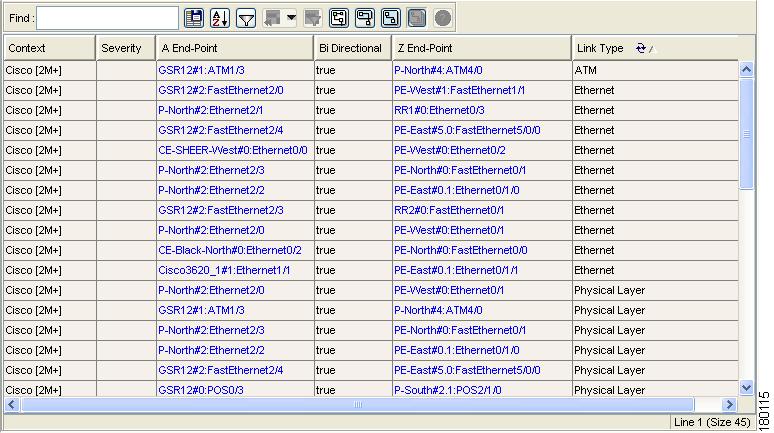
Links View
The links view is displayed in the Cisco ANA NetworkVision window when clicking
on the toolbar.
When the user views a map, it may, for example, have many links or aggregated links. This may make it difficult for the user to view the links that are required. The links view enables the user to clearly view the required links, and in addition the user can easily search for a specific link. The links view provides the user with an easy to access complete list of the various types of links displayed on the map (the links view is context sensitive). The user can also view the status of the link.
Note
Note
Any links that are added or removed from the map are automatically added or removed from the links view provided they have not been filtered out.
The links view is selection sensitive, namely, the links displayed in the links view depend on the context selected in the tree pane or map pane. For example, if an aggregated node or aggregated link is selected then the links of the selected context are displayed in the links view.
The links view is displayed below.
Figure 2-2 Links View
Note
The following columns are displayed in the Links View window:
•
•
•
•
•
•
Note
The following additional buttons are displayed at the top of the links view (navigation sensitive) and enable you to filter the links using the collection method:
All Links—Displays the complete list of links for the selected context (map, aggregation, or sub-aggregation), namely, the list is not filtered and all the links are displayed (including external links).
External Links—Displays the links where only one side of the link starts in this context (map, aggregation or sub-aggregation) and the other side ends somewhere else, namely, is not in the map or is outside the currently selected context.
Flat Links (Surface)—Displays the links currently visible on the map for the selected context (map, aggregation or sub-aggregation), excluding, any thumbnails.
Deep Links—Displays the links for the current aggregations and the sub-aggregations where both of the endpoints are somewhere within the currently selected context.
For more information about filtering and sorting links in links view, see Working in Links View, page 7-8.
Ticket Pane
When Cisco ANA detects faulty behavior in the network, the VNEs and their internal Device Components initiate an internal, end-to-end message flow, resulting in full understanding and containment of the fault across all relevant network elements and network layers.
The ticket pane is displayed beneath the tree pane and workspace in the Cisco ANA NetworkVision window. The ticket pane can be displayed or hidden by clicking the arrows displayed below the tree pane. For the definition of a ticket, alarm and event, see Events, Tickets and Alarm Definitions, page 1-3.
For more information about tickets, refer to the Cisco Active Network Abstraction EventVision User Guide.
A network event is a discrete occurrence or happening in the network at a specific point in time. Events are determined from incoming traps, syslogs and detected device changes. A system event is an occurrence or happening, usually significant to the performance of a function, operation or task in the Cisco ANA system. Examples of events include port status change; device reset or reloads of a Cisco ANA VNE. Cisco ANA EventVision enables you to view the event history. For more information, refer to the Cisco Active Network Abstraction EventVision User Guide.
Tickets represent an entire lifecycle within the system and include a chain of related events and alarms, from the time that the alarm is opened (when the change in behavior is first detected) until it is acknowledged, resolved and closed. Examples of alarms are link down, device unreachable or module out. Some event types are capable of creating tickets. When an event is generated it is correlated to an existing event which is correlated to a ticket. If there is no existing ticket then a new ticket is created.
The ticket pane enables you to view and manage tickets as well as pinpoint the source of the ticket. All the tickets that are reported by Cisco ANA are stored in Cisco ANA Gateway's database.
Cisco ANA identifies the relationship between a root cause alarm and its consequent alarms. It automatically correlates the consequent alarms as "children" of the root alarm. The ticket pane displays the ticket (namely, the root cause alarm) and the Ticket Properties dialog box enables you to view all correlated alarms.
Note
The ticket pane enables you to perform the following functions:
•
•
see Filtering Tickets by Criteria, page 8-4.•
•
•
•
•
•
•
The following columns are displayed in the ticket pane:
•
–
–
–
–
–
–
Note
–
For more information about severity, see Map Pane.
•
•
Note
•
•
•
•
•
•
•
•
The ticket details in the ticket pane change constantly as they are updated with new information. For example, Port Down is updated to Port Up.
The tickets in the ticket pane are by default sorted according to Ticket ID. For information about tickets, see Chapter 8, "Working with Tickets".
The Location field displays the number of selected rows and the total number of rows in the table, for example, 2/16 Selected. In addition, it displays the location of the selected row(s) in the table, for example, Line 3.
The Find field enables you to search for information in the ticket pane table according to the selected column. For more information about the buttons displayed in Cisco ANA NetworkVision's tables and table functionality, see Working with Tables, page 3-1.
For more information about how the status of a network device is displayed in the ticket pane, see Status of Network Objects.
Status of Network Objects
The status of a network object is displayed in Cisco ANA NetworkVision in the following ways:
Severity
Severity indicates the "operational health" of the network device. At any give time an icon has only one severity value and this value is displayed using the severity colors. For more information about the colors used to display the severity (or propagated severity) of network devices and links, see Map Pane.
Propagation
Severity is propagated upwards in the network hierarchy, displaying the topmost severity of its children and so ensuring that every single problem in the network is propagated and visible.
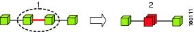
The same severity propagation rules that are used for network elements, apply to links. A link is a child object of an aggregation if and only if it is fully contained in the aggregation; namely, the network elements on both sides of the link are part of the aggregation, as displayed in the examples below.
Figure 2-3 Link Severity Example 1
In the example above there is a critical link (#1) between two NEs in an aggregation. This will affect the severity of the aggregation (#2), namely, the aggregation will be critical because it contains a link with a critical severity. Link severity affects the context.
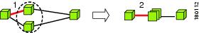
Figure 2-4 Link Severity Example 2
In the example above there is one critical link (#1) that forms part of an aggregated link. This will affect the severity of the aggregated link (#2), because it contains a link with a critical severity.
New Ticket Propagation
A new ticket indicates a new local fault or accumulates and propagates the number of new faults in its children. New tickets are propagated upwards, displaying the number of new tickets and the topmost severity.
When new tickets are accumulated, a label is displayed in the tree pane and map pane, based on the following formula:
<n> <s> [+]
Where:
n =
Displays the number of tickets with the highest severity in the new ticket count.
s =
Displays the highest severity level in the new tickets:
•
•
•
•
•
+ =
Indicates that additional, less severe tickets (optional) exist
The color of the bell displays the topmost severity level(s).
Examples:
•
•
Management State
The management state indicates the state/mode of the software component (a VNE) managing a network device and the communication with it. This enables you to determine the accuracy of the network information and the availability of the Cisco ANA VNEs in order to carry out network operations.
Management states are always local indications and are not propagated. A partial exception to this rule is the propagation of unreachable network elements.
The management state indication only applies to network elements and network element components. A network object can only have one state, for example, unsupported or initializing.
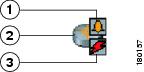
A network device icon consists of two components, a device icon and an overlay icon that reflects the status, namely, the severity, management state or new alarm.
The device icon displays a symbol of the network device and the color of the symbol displays the severity (or propagated severity) of the network device. For more information about device icons, see Device Icons, page A-1. For more information about severity colors, see Map Pane.
A small overlay icon is displayed on top of the device icon to indicate the management state in the tree pane and map pane. For example, a Router that Cisco ANA failed to access (unreachable) is displayed as illustrated below:
Figure 2-5 Device with Overlay Icons
Cisco ANA NetworkVision supports the following management states:
Table 2-4 Management States
Unsupported
The VNE does not support the network object hardware or software version or a device module.
Initializing
The VNE or VNE component is in startup mode or is temporarily non-operational.
VNE Unreachable
Cisco ANA Gateway received no response from the VNE.
Device Unreachable
Cisco ANA failed to access the device.
Partially Supported
The group of devices is supported in general, but the specific device is only partially supported.
Maintenance
The VNE state was manually changed to maintenance or when adaptive polling is implemented (CPU usage is high), so the VNE is no longer polled and the VNE automatically moves to maintenance mode (for more information, refer to the Cisco Active Network Abstraction Administrator Guide. The NE is working (status Up), but if there are any alarms or tickets that are generated on the device they will not be sent to the application.
Unknown
The device (ghost) type is unknown.
Operational
Fully functional.
NE icon
NE icon
More than one management state can occur at the same time. In this case, a single overlay icon is displayed reflecting the device status based on the following priorities: Unsupported > Initializing > VNE Unreachable > Device Unreachable > Partially Supported > Operational.
Tickets
A bell icon is displayed in the tree pane, map pane and ticket pane to indicate tickets. Every alarm is assigned a severity level, representing the impact of the fault on the network device. The bell icon displays the severity level of the topmost alarm. An example is displayed below.
Cisco ANA NetworkVision Toolbar
The Cisco ANA NetworkVision toolbar is context-sensitive and the options vary depending on your selection in the application.
Note
The Cisco ANA NetworkVision window contains the following tools:
Table 2-5 Cisco ANA NetworkVision Toolbar
Creates a new map in the database.
Opens a file/map saved in the database using the Open dialog box.
Saves the current map, for example, the background and the location of devices, to the database.
Adds a device to the map or to the sub-network selected in the tree pane and displayed in the map pane.
Adds a VPN (that has not yet been loaded) to the currently displayed map. For more information, refer to the Cisco Active Network Abstraction Managing MPLS User Guide.
Opens the Inventory window enabling you to view the physical and logical inventory of a device.
Aggregates the devices selected in the map pane of the Cisco ANA NetworkVision window and enables you to define a name for the aggregated device.
Opens the Map Options dialog box, enabling the network administrator to display or hide different types of links on the map and in the links view.
Defines the size of a selected device(s) or aggregated nodes in the map pane, according to predefined sizes or according to a percentage of the current size.
Choose and display an overlay of a specific VPN on top of the devices displayed in the network map of the map pane using the Choose Overlay dialog box.
When a VPN in the network is selected all the devices and links that are part of the VPN are colored and those that are not part of the VPN are grayed out. The ones that remain highlighted are the provider edge routers and the physical links that carry the LSP that is being used by the VPN. For more information, refer to the Cisco Active Network Abstraction Managing MPLS User Guide.
After a selection is made by clicking Choose Overlay, displays or hides a previously defined overlay of a specific VPN on top of the physical devices displayed in the network map of the map pane.
For more information, refer to the Cisco Active Network Abstraction Managing MPLS User Guide.
Opens the Find Business Tag dialog box, enabling the network administrator to find and/or delete a business tag according to a name, key or type.
Moves up a branch in the tree pane and map pane in order to view different information.
Finds a device or aggregated node in the network/map according to the name.
Defines the way in which the map lays out the NEs in the map pane of the Cisco ANA NetworkVision window, namely, Circular, Symmetric, tree or Hierarchical.
Displays the device view in the Cisco ANA NetworkVision window (the button toggles when selected or deselected).
Displays the links view in the Cisco ANA NetworkVision window (the button toggles when selected or deselected).
Displays the map pane in the Cisco ANA NetworkVision window (the button toggles when selected or deselected).
Opens a window displaying an overview of the network.
Activates the normal selection mode (the button toggles when selected or deselected).
Activates the pan mode, which enables you to move around in the map pane by clicking and dragging (the button toggles when selected or deselected).
Activates the zoom selection mode, which enables you to select an area in the map pane to be enlarged by clicking and dragging to view the selected area (the button toggles when selected or deselected).
Fits the entire sub-network/map in the map pane.
Menu Bar
This section provides a description of each option available in the Cisco ANA NetworkVision menus. The following menus are available:
Note
Note
File Menu
The File menu displays the following options (for more information see Chapter 4, "Working with Cisco ANA NetworkVision Maps"):
New Map
Creates a new map in the database.
Open
Opens a file/map saved in the database using the Open dialog box.
Close Map
Closes the map currently displayed in the Cisco ANA NetworkVision window.
Load Path Tracer
Loads a Cisco ANA PathTracer map from a previously saved file in the Cisco ANA PathTracer Multi-Path window.
Add Device
Opens the device view and enables you to add a device to the map or to the sub-network selected in the tree pane and displayed in the map pane. This option is enabled when a map is open and you have the relevant security level, namely, OperatorPlus.
Add VPN
Adds a VPN (that has not yet been loaded) to the currently displayed map. For more information, refer to the Cisco Active Network Abstraction Managing MPLS User Guide.
Note
Save Map
Saves the appearance of the map, for example, the background and the location of devices, to the database. This option is enabled when a map is open and you have the relevant security level, namely, OperatorPlus.
Save As Image
Saves the active map as an image and automatically displays the Save as Image dialog box. Use this dialog box to save an image using a different file format or name.
Print Preview
Displays each map, as it will look when printed.
Prints the active map as displayed in the Print Preview dialog box.
Exit
Exits the Cisco ANA NetworkVision application and saves the workspace.
Edit Menu
The Edit menu displays the following options:
Find in Map
Searches for a device in the network/map that contains the specified text in the name or the IP fields.
Find Business Tag
Searches for business tag information in the database.
Resize
Displays the Resize dialog box, enabling you to define the percentage used to resize device icon(s) or aggregated nodes in the map pane.
Note
View Menu
The View menu displays the following options:
Layout
Defines the way in which the map is displayed in the map pane of the Cisco ANA NetworkVision window's workspace, namely, Circular, Symmetric, Tree or Hierarchical.
Overview
Opens a window displaying an overview of the network map.
Zoom In
Zooms in on the network map.
Zoom Out
Zooms out of the network map.
Fit In Window
Displays the entire network map in the map pane.
Normal Select
Activates the normal selection mode. The selected option is grayed out.
Pan
Activates the pan mode, which enables you to move around in the map pane by clicking and dragging. The selected option is grayed out.
Zoom Selection
Activates the zoom selection mode, which enables you to select an area in the map pane to be enlarged by clicking and dragging to view the selected area. The selected option is grayed out.
Node Menu
The Node menu displays the following options:
Note
Inventory
Displays a dialog box enabling you to view the physical and logical inventory. For physical inventory you can view all the components of the device, for example, modules and ports. In addition, you can view the status of each component. For logical inventory you can view all the profiles and VC or routing tables of the device. For more information see Chapter 6, "Viewing Network Device Inventory".
Aggregate
Groups the selected devices into an aggregation in the map pane of the Cisco ANA NetworkVision window's workspace and enables you to define a name for the aggregated node. For more information see Chapter 4, "Working with Cisco ANA NetworkVision Maps".
Disaggregate
Ungroup the selected aggregated node in the tree pane and map pane of the Cisco ANA NetworkVision window. All the nodes in the selected aggregation move up one level and the selected aggregation is removed. For more information see Chapter 4, "Working with Cisco ANA NetworkVision Maps".
Note
Mark as A Side
Starts the process of creating a new static link. This option is enabled when a device, port or unmanaged network is selected.
Mark as Z Side
Launches the Add Static Link dialog box, enabling you to create a static link between to the two selected nodes. This option is enabled after a device, port or unmanaged network is selected and after the Mark as A Side option is selected.
Note
Properties
Displays a dialog box enabling you to view the properties of the selected device, for example, the severity, IP address and communication state. For more information see Chapter 5, "Viewing Device Properties".
Tools Menu
The Tools menu displays the following options:
Change User Password
Enables you to change the password used when logging in to the Cisco ANA Client application suite. The change will take effect the next time that the user logs in to the application.
Note
Options
Enables you to customize several of Cisco ANA NetworkVision's options, for example, load workspace on startup. For more information
see Selecting Cisco ANA NetworkVision Map and Alarm Options.Window Menu
The Window menu displays the names of all the maps open in the Cisco ANA NetworkVision window's workspace enabling you to move between the maps.
Help Menu
The Help menu provides the user with information about Cisco ANA NetworkVision and provides access to the Help.
Cisco ANA NetworkVision Help
Opens the Cisco ANA NetworkVision online Help.
Cisco.com
This option is currently unavailable in this version.
About Cisco ANA NetworkVision
Displays application information about Cisco ANA NetworkVision, for example, the version number.
Shortcut Menus
Right-clicking in a specific area or on a link, device or alarm in the Cisco ANA NetworkVision window opens the following shortcut menus:
•
A shortcut menu is displayed when you right-click in many of Cisco ANA NetworkVision's dialog boxes or tables. For example, you can open a map from the Map List dialog box using the shortcut menu. The options displayed vary depending on the dialog box or tables currently displayed and the selection. For more information about any of the shortcut menu options displayed, refer to the options discussed in this section.
Note
•
Device Shortcut Menu
The Device shortcut menu is displayed when you right-click a device in the tree pane, and workspace.
Note
Inventory
Displays a window enabling you to view the physical and logical inventory. For physical inventory, you can view all the components of the device, for example, modules, ports, and its IP address or configured VLANs. In addition, you can view the status of each component. For logical inventory, you can view all the profiles and VC tables of the device. For more information see Chapter 6, "Viewing Network Device Inventory".
Aggregate
Aggregates the devices selected in the map pane of the Cisco ANA NetworkVision window and enables you to define a name for the aggregated device. For more information see Chapter 4, "Working with Cisco ANA NetworkVision Maps".
Disaggregate
Ungroup the selected aggregated node(s) in the tree pane and map pane of the Cisco ANA NetworkVision window. For more information see Chapter 4, "Working with Cisco ANA NetworkVision Maps".
Note
Attach Business Tag
Attaches a business tag to the selected network element. For more information see Chapter 10, "Working with Business Tags".
Detach/Edit
You can detach or edit a business tag from the selected Network Object. For more information see Chapter 10, "Working with Business Tags".
Note
Filter Tickets
Filters the tickets shown in the ticket pane so that it only displays the tickets of a selected device/network element.
Resize
Displays the Resize dialog box that enables you to define the percentage used to resize the device icon(s) or aggregated nodes in the map pane.
Remove from Map
Removes the selected device and all its children from the map (tree pane and workspace). The device that has been removed is still maintained in the network.
Save as new map
Creates a new map and places the selected aggregation as the root, while leaving the original map intact.
Tools
The Tools option contains the following sub-menu options:
•
•
•
Topology
The Topology option enables you to:
•
•
It contains the following sub-menu options in order to define the A Side and Z Side of the link:
•
•
When working with VPNs in VPN Service View, the Topology sub-menu allows you define and configure tunnels. For more information, refer to the Cisco Active Network Abstraction Managing MPLS User Guide.
Properties
Displays the properties of the selected device, for example, IP address and system name. In addition, you can open the VNE Properties dialog box and manage VNE properties. For more information see Chapter 6, "Viewing Network Device Inventory".
VNE Tools
Changes the status of the VNE by starting or stopping the VNE. For more information see Chapter 5, "Viewing Device Properties".
Management
It contains the following sub-menu options:
•
•
Map Shortcut Menu
The Map shortcut menu is displayed when you right-click anywhere on a map in the map pane.
Go to Parent
Goes to the parent in the tree pane and map pane in order to view different information.
Go to Root
Goes to the root in the tree pane and map pane in order to view different information.
Aggregate
Creates an aggregation of the selected nodes in the tree pane and map pane of the Cisco ANA NetworkVision window and enables you to define a name for the aggregation. For more information see Chapter 4, "Working with Cisco ANA NetworkVision Maps".
Filter Tickets
Filters the tickets shown in the ticket pane so that it only displays the tickets of a selected device/network element.
Aggregated Node Shortcut Menu
The Aggregated Node shortcut menu is displayed when you right-click on an aggregated node in the map pane.
Aggregate
Aggregates the devices selected in the map pane of the Cisco ANA NetworkVision window and enables you to define a name for the aggregated device. For more information see Chapter 4, "Working with Cisco ANA NetworkVision Maps".
Disaggregate
Ungroup the selected aggregated node in the tree pane and map pane of the Cisco ANA NetworkVision window. For more information see Chapter 4, "Working with Cisco ANA NetworkVision Maps".
Note
Filter Tickets
Filters the tickets shown in the ticket pane so that it only displays the tickets of the selected aggregated node.
Rename
Renames the selected aggregated node.
Resize
Defines the size of selected devices or aggregated nodes in the map pane according to predefined sizes or according to a percentage of the current size.
Remove from Map
Removes the selected aggregated node and all its children from the map (tree pane and map pane).
Save as New map
Creates a new map and places the selected aggregation as the root, while leaving the original map intact.
Show Thumbnail
Displays a thumbnail of the selected aggregated node in the map pane, including all the aggregated devices.
Show as Aggregation
Displays the aggregated node in the map pane.
Note
Link Shortcut Menu
The Link shortcut menu is displayed when you right-click a link in the map pane. For more information see Chapter 7, "Working with Links".
Filter Tickets
Filters the tickets shown in the ticket pane so that it only displays the tickets of a selected Network Object.
Properties
Displays the properties of the selected link.
Links View Shortcut Menu
The Links View shortcut menu is displayed when you right-click a link in the links view table displayed in the Cisco ANA NetworkVision window's workspace. For more information see Chapter 7, "Working with Links".
Attach Business Tag
Attaches a business tag to the selected link. For more information see Chapter 10, "Working with Business Tags".
Detach/Edit
You can detach or edit a business tag from the selected link. For more information see Chapter 10, "Working with Business Tags".
Note
Find Source
Finds the link source, if it exists, by highlighting the link in the map pane.
Properties
Displays the properties of the selected link.
Ticket Shortcut Menu
The Ticket menu is displayed when you right-click the ticket in the ticket pane. The Ticket menu enables the network administrator to view ticket properties and to highlight a device that is the source of a ticket. The Ticket menu also enables you to acknowledge, clear and remove a ticket. For more information see Chapter 8, "Working with Tickets".
Acknowledge
Acknowledges that the ticket is being handled and the ticket is displayed as true in the ticket pane. Acknowledging an alarm removes the alarm icon from the device icon.
Note
Clear
Approves the reported faulty ticket and clears the faulty networking entity from Cisco ANA. The ticket is displayed as Clear in the ticket pane.
Note
Remove
Removes the ticket and all its active sub-tickets from the ticket pane (this option is only available after the ticket has been cleared). The deleted tickets can be viewed using Cisco ANA EventVision.
Note
•
Clear and Remove
Approves the reported faulty ticket and clears the faulty networking entity from Cisco ANA. In addition, the ticket, and all its active sub-tickets are removed from the ticket pane.
Find Source
Finds the ticket source, if it exists, by highlighting the device or link in the map pane.
Properties
Displays the Ticket Properties dialog box enabling you to view ticket information, including impact analysis details of the affected parties and correlated alarms.
Changing a User Password
Cisco ANA NetworkVision enables the user to change his/her login password.
Note
Note
•
•
•
To change a user password:
Step 1
The following fields are displayed in the Change User Password dialog box:
•
•
•
Step 2
Note
Selecting Cisco ANA NetworkVision Map and Alarm Options
Cisco ANA NetworkVision enables you to customize the startup and display options.
To customize Cisco ANA NetworkVision:
Step 1
The following checkbox is displayed in the Workspace Info area:
•
The Display tab enables you to define the display options for the application, for example, whether business tags are displayed. The Display tab is shown below.
The following checkboxes are displayed in the Severity area:
•
•
•
The following radio buttons are displayed in the Display Name area:
•
•
•
The Audio tab enables you to define whether sounds are used when an alarm is triggered and what these sounds will be.
You can select whether or not sound alarms are enabled, by selecting the Enable Audio Response for Alarm checkbox is displayed at the top of the Audio tab.
Selecting the Enable Audio Response for Alarm option enables the chosen sound files to be played when an alarm is triggered. You can select different sound files for critical, major, and minor alarms.
The following fields are displayed in the Alarm area:
•
•
•
The following checkbox is displayed in the Alarm area:
•
Step 2
Step 3
Logging Out
When you have finished working with Cisco ANA NetworkVision you can log out of the application. Any open maps and the workspace are automatically saved when you log out.
To log out of Cisco ANA NetworkVision:
Step 1
Step 2
Note