-
Cisco Wireless Control System Configuration Guide, Release 5.1
-
Preface
-
Chapter 1: Overview
-
Chapter 2: Getting Started
-
Chapter 3: Configuring Security Solutions
-
Chapter 4: Performing System Tasks
-
Chapter 5: Adding and Using Maps
-
Chapter 6: Monitoring Wireless Devices
-
Chapter 7: Managing WCS User Accounts
-
Chapter 8: Configuring Mobility Groups
-
Chapter 9: Configuring Access Points
-
Chapter 10: Configuring Controllers and Switches
-
Chapter 11: Using Templates
-
Chapter 12: Performing Maintenance Operations
-
Chapter 13: Configuring Hybrid REAP
-
Chapter 14: Alarms and Events
-
Chapter 15: Running Reports
-
Chapter 16: Administrative Tasks
-
Chapter 17: Virtual Domains
-
Chapter 18: Google Earth Maps
-
Appendix A: Troubleshooting and Best Practices
-
Appendix B: WCS and End User Licenses
-
Appendix C: Conversion of a WLSE Autonomous Deployment to a WCS Controller Deployment
-
Index of Cisco Wireless Control System Configuration Guide, Version 5.1
-
 Feedback
Table Of Contents
Configuring Controllers and Switches
Setting Multiple Country Codes
Managing User Authentication Order
Viewing Audit Status (for Controllers)
Viewing Latest Network Audit Report
Pinging a Network Device from a Controller
Enabling Load-Based CAC for Controllers
Optimizing the Controller to Support High Density
Configuring an RRM Threshold Controller (for 802.11a/n or 802.11b/g/n)
Configuring 40-MHz Channel Bonding
Configuring EDCA Parameters for Individual Controller
Configuring NAC Out-of-Band Integration
Guidelines for Using NAC Out-of-Band Integration
Configuring NAC Out-of-Band Integration
Configuring Wired Guest Access
Creating a Wired LAN for Guest Access
Configuring Controllers and Switches
This chapter describes how to configure controllers and switches in the Cisco WCS database. This chapter contains the following sections:
•
Setting Multiple Country Codes
•
•
•
•
•
•
•
•
•
•
•
Adding Controllers
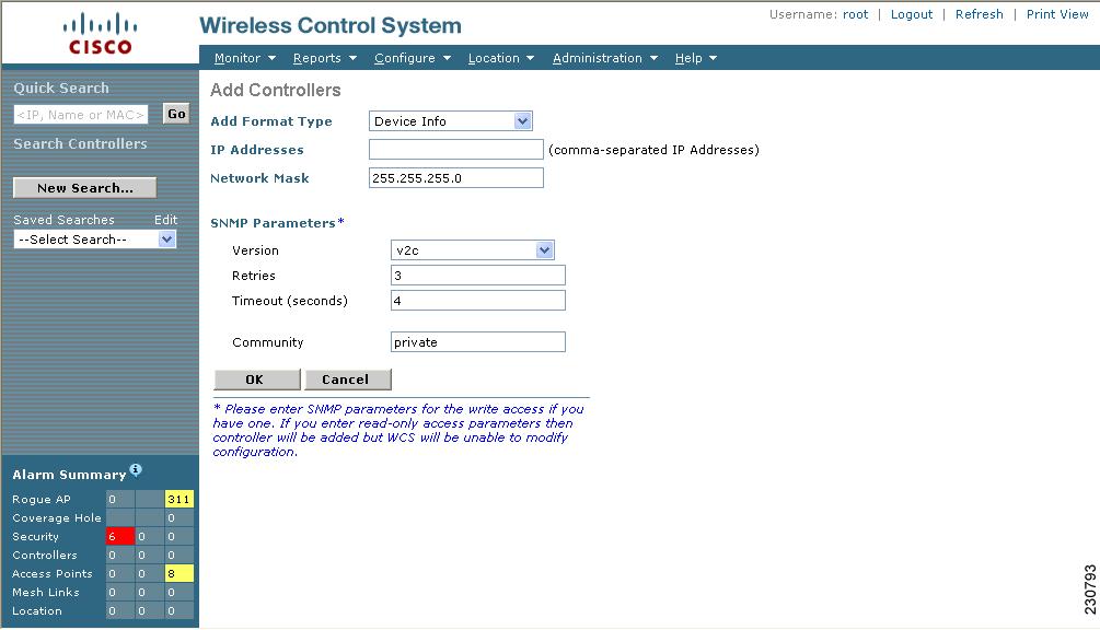
You can add controllers one at a time or in batches. Follow these steps to add controllers.
Step 1
Step 2
Figure 10-1 Add Controller Window
Step 3
If you want to add one controller or use commas to separate multiple controllers, leave the Add Format Type drop-down menu at Device Info.
If you want to add multiple controllers by importing a CSV file, choose File from the Add Format Type drop-down menu. The CSV file allows you to generate your own import file and add the devices you want.
Note
Step 4
Note
If you chose File, click Browse... to find the location of the CSV file you want to import.
Step 5
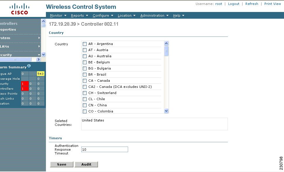
Setting Multiple Country Codes
To set multiple country support for a single controller(s) that is not part of a mobility group, follow the steps below.
Step 1
Step 2
Step 3
Figure 10-2 Controller 802.11
Step 4
Note
Step 5
Step 6
Searching Controllers
Use the controls in the left sidebar to create and save custom searches:
•
•
•
You can configure the following parameters in the Search Controllers window:
•
•
•
•
–
–
–
•
After you click GO, the controller search results appear:
Managing User Authentication Order
You can control the order in which authentication servers are used to authenticate a controller's management users.
Step 1
Step 2
Step 3
Step 4
Step 5
Viewing Audit Status (for Controllers)
You can audit a controller by choosing Audit Now from the Select a command drop-down menu in the Configure > Controllers window or by clicking Audit Now directly from the Controller Audit Report.
Note
To audit a controller, follow these steps:
Step 1
Step 2
Step 3
Step 4
Step 5
The Audit Report displays the following:
•
•
•
•
–
–
–
–
–
–
•
–
–
–
–
–
•
•
Note
Applied and Config Group Template Discrepancies
Total enforcements for config groups with background audit enabled
Failed enforcements for config groups with background audit enabled
Config WCS discrepancies
The following sections are displayed if the audit is selected to be a basic audit:
Config WCS discrepancies•
–
Note
–
Retain—The WCS refreshes the configuration from the controller but will not delete any devices or configurations that no longer exist in the controller configuration. For example, if the WCS database shows an AP1, but that access point is no longer present in the controller configuration, WCS will not delete AP1 from its database.
Delete—WCS deletes the configuration of the controller from its database and retrieves a new configuration from the controller. Delete is the recommended option so that WCS matches the most recent configuration you are refreshing from WLCs.
Note
Viewing Latest Network Audit Report
The Network Audit Report shows the time of the audit, the IP address of the selected controller, and the synchronization status. The Applied and Config Group Template Discrepancies, Total Enforcements for Config Groups with Background Audit Enabled, and Failed Enforcements for Config Groups with Background Audit Enabled sections have data only if the network audit was run as a template based audit.
Note
To view the latest network audit report for the selected controllers, follow these steps:
Step 1
Step 2
Step 3
Step 4
The Audit Summary displays the time of the audit, the IP address of the selected controller, and the audit status. The Audit Details display the config differences, if applicable.
You can use the General and Schedule tabs to revise the Audit Report parameters.
Note
Note
Setting AP Failover Priority
When a controller fails, the backup controller configured for the access point suddenly receives a number of discovery and join requests. This may cause the controller to reach an overloaded point and reject some of the access points.
By assigned priority to an access point, you have some control over which access points are rejected. In a failover situation when the backup controller is overloaded, the higher-priority access points join the backup controller and disjoin the lower priority access points.
To configure priority settings for access points, you must first enable the AP Priority feature. To enable the AP Priority feature, follow these steps:
Step 1
Step 2
Step 3
Step 4
To then configure an access point's priority, follow these steps:
Step 1
Step 2
Note
Pinging a Network Device from a Controller
Follow these steps to ping network devices from a controller.
Step 1
Step 2
Step 3
Step 4
Step 5
WCS displays the Ping Results window, which shows the packets that have been sent and received. Click Restart to ping the network device again or click Close to stop pinging the network device and exit the Ping Results window.
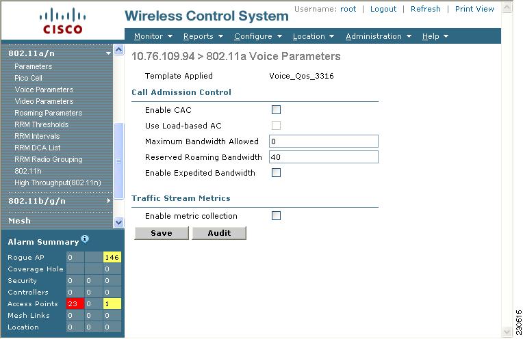
Enabling Load-Based CAC for Controllers
Load-based CAC incorporates a measurement scheme that takes into account the bandwidth consumed by all traffic types from itself, from co-channel access points, and by co-located channel interference. Load-based CAC also covers the additional bandwidth consumption resulting from PHY and channel impairment.
In load-based CAC, the access point periodically measures and updates the utilization of the RF channel, channel interference, and the additional calls that the access point can admit. The access point admits a new call only if the channel has enough unused bandwidth to support that call. By doing so, load-based CAC prevents over-subscription of the channel and maintains QoS under all conditions of WLAN loading and interference.
To enable load-based CAC for a controller template, refer to the "Configuring a Voice Parameter Template (for 802.11a/n or 802.11b/g/n)" section on page 11-61.
To enable load-based CAC for a controller using the WCS web interface, follow these steps.
Step 1
Step 2
Step 3
The 802.11a/n (or 802.11b/g/n) Voice Parameters page appears (see Figure 10-3).
Figure 10-3 802.11a/n Voice Parameters Page
Step 4
Step 5
Step 6
Step 7
Step 8
Step 9
Step 10
Enabling High Density
The high density deployments are enabled with Cisco Unified Wireless Network software release 4.1 in conjunction with the Cisco and Intel Business Class Suite Version 2 initiative.
The high density networking feature is designed for large, multi-cell high density wireless networks in which it can be challenging to populate a site with a large number of lightweight access points to manage the cumulative bandwidth load while diminishing the contention between access points and still maintaining quality of service. To optimize RF channel capacity and improve network performance, the high density (or pico cell) mode parameters are introduced.
With this feature you can manually configure the transmit power, receiver sensitivity thresholds, and clear channel assessment sensitivity threshold of Intel client devices and Cisco Aironet lightweight access points in order to create optimal high-density deployments. When a client that supports high density associates to an access point with high-density enabled, they exchange specific 802.11 information element s (IEs) that instruct the client to adhere to the access point's advertised received sensitivity threshold, CCA sensitivity threshold, and transmit power levels. These three parameters reduce the effective cell size by adjusting the received signal strength before an access point and client consider the channel accessible for the transfer of packets. When all access points and clients raise the signal standard in this way throughout a high density area, access points can be deployed closer together, minimizing interference with each other and managing environmental and distant rogue signals.
Note
Along with these configuration changes, you can further optimize the pico cell deployment as follows:
Requirements
High density has the following restrictions:
•
•
Note
Optimizing the Controller to Support High Density
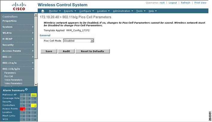
To optimize a controller to support high density, you need to enable pico cell mode v2. A method to mitigate the inter-cell contention problem in high-density networks is to adjust the access point and client receiver sensitivity, CCA sensitivity, and transmit power parameters in a relatively cooperative manner. By adjusting these variables, the effective cell size can be reduced, not by lowering the transmit power but by increasing the necessary received power before an access point and client consider the channel sufficiently clear for packet transfer. These similar values can be set in the Controller Templates portion of the GUI. Refer to Applying Controller Templates, page 11-79. Follow these steps to configure high density.
Note
Step 1
Step 2
Figure 10-4 Pico Cell Parameter
Step 3
Note
Step 4
Step 5
Figure 10-5 Pico Cell Parameters Window
Note
Step 6
Note
Step 7
Step 8
Step 9
Step 10
Step 11
Configuring 802.3 Bridging
The controller supports 802.3 frames and applications that use them, such as those typically used for cash registers and cash register servers. However, to make these applications work with the controller, the 802.3 frames must be bridged on the controller.
Support for raw 802.3 frames allows the controller to bridge non-IP frames for applications not running over IP. Only this raw 802.3 frame format is currently supported.
You can configure 802.3 bridging using WCS release 4.1 or later. Follow these steps.
Step 1
Step 2
Step 3
Step 4
Configuring an RRM Threshold Controller (for 802.11a/n or 802.11b/g/n)
Follow these steps to configure an 802.11a/n or 802.11b/g/n RRM threshold controller.
Step 1
Step 2
Step 3
Step 4
Note
Step 5
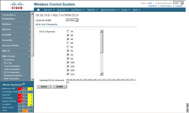
Configuring 40-MHz Channel Bonding
The Radio Resource Management (RRM) Dynamic Channel Assignment (DCA) page allows you to choose the DCA channels as well as the channel width for this controller.
RRM DCA supports 802.11n 40-MHz channel width in the 5-GHz band. The higher bandwidth allows radios to achieve higher instantaneous data rates.
Note
To configure 802.11 a/n RRM DCA channels for an individual controller, follow these steps:
Step 1
Step 2
Step 3
Note
Figure 10-6 802.11a/n RRM DCA Window
Step 4
Note
Note
Step 5
Step 6
Configuring EDCA Parameters for Individual Controller
The EDCA parameters (EDCA profile and Streaming MAC Enable settings) for 802.11a/n and 802.11b/g/n can be configured either by individual controller or through a controller template to improve voice QoS support. Refer to the "Configuring EDCA Parameters through a Controller Template" section on page 11-63 for steps to configure a controller template.
To configure 802.11a/n or 802.11b/g/n EDCA parameters for an individual controller, do the following:
Step 1
Step 2
Step 3
Step 4
Note
Note
Step 5
Note
Configuring SNMPv3
When you are configuring a controller, you can add SNMPv3 settings or change the setting (and any other settings) established from the previously added controller. Follow these steps to set the SNMPv3 settings.
Step 1
Step 2
Step 3
Step 4
Step 5
Step 6
Step 7
Viewing All Current Templates
Prior to software release 5.1, templates were detected when a controller was detected, and every configuration found on WCS for a controller had an associated template. Now templates are not automatically detected with controller discovery, and you can specify which WCS configurations you want to have associated templates.
The following rules apply for template discovery:
•
•
•
Follow these steps to use the Discover Templates from Controller feature:
Step 1
Step 2
Step 3
Step 4
Note
Configuring NAC Out-of-Band Integration
The Cisco NAC Appliance, also known as Cisco Clean Access (CCA), is a network admission control (NAC) product that allows network administrators to authenticate, authorize, evaluate, and remediate wired, wireless, and remote users and their machines prior to allowing users onto the network. It identifies whether machines are compliant with security policies and repairs vulnerabilities before permitting access to the network. The NAC appliance is available in two modes: in-band and out-of-band. Customers can deploy both modes if desired, each geared toward certain types of access (in-band for supporting wireless users and out-of-band for supporting wired users, for example).
In WCS software releases prior to 5.1, the controller integrates with the NAC appliance only in in-band mode, where the NAC appliance must remain in the data path. For in-band mode, a NAC appliance is required at each authentication location (such as at each branch or for each controller), and all traffic must traverse the NAC enforcement point. In WCS software release 5.1, the controller can integrate with the NAC appliance in out-of-band mode, where the NAC appliance remains in the data path only until clients have been analyzed and cleaned. Out-of-band mode reduces the traffic load on the NAC appliance and enables centralized NAC processing.
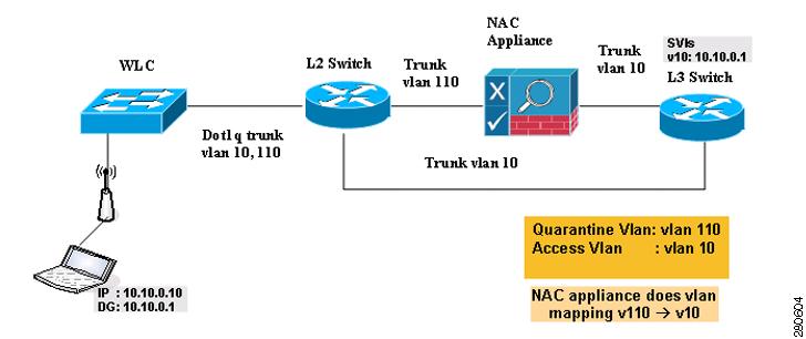
To implement the NAC out-of-band feature on the controller, you need to enable NAC support on the WLAN or guest LAN and then map this WLAN or guest LAN to an interface that is configured with a quarantine VLAN (untrusted VLAN) and an access VLAN (trusted VLAN). When a client associates and completes Layer 2 authentication, the client obtains an IP address from the access VLAN subnet, but the client state is Quarantine. While deploying the NAC out-of-band feature, be sure that the quarantine VLAN is allowed only between the Layer 2 switch on which the controller is connected and the NAC appliance and that the NAC appliance is configured with a unique quarantine-to-access VLAN mapping. Client traffic passes into the quarantine VLAN, which is trunked to the NAC appliance. After posture validation is completed, the client is prompted to take action for remediation. After cleaning is completed, the NAC appliance updates the controller to change the client state from Quarantine to Access. Figure 10-7 provides an example of NAC out-of-band integration.
Figure 10-7 NAC Out-of-Band Integration
In Figure 10-7, the link between the controller and the switch is configured as a trunk, enabling the quarantine VLAN (110) and the access VLAN (10). On the Layer 2 switch, the quarantine traffic is trunked to the NAC appliance while the access VLAN traffic goes directly to the Layer 3 switch. Traffic that reaches the quarantine VLAN on the NAC appliance is mapped to the access VLAN based on a static mapping configuration.
Follow the instructions in this section to configure NAC out-of-band integration.
Note
Guidelines for Using NAC Out-of-Band Integration
Follow these guidelines when using NAC out-of-band integration:
•
•
•
•
•
Note
•
•
•
Note
Configuring NAC Out-of-Band Integration
Follow these steps to configure NAC out-of-band integration.
Step 1
a.
b.
c.
d.
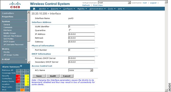
Figure 10-8 Interface Window
e.
f.
g.
Note
Note
h.
i.
j.
Step 2
a.
b.
c.
Note
d.
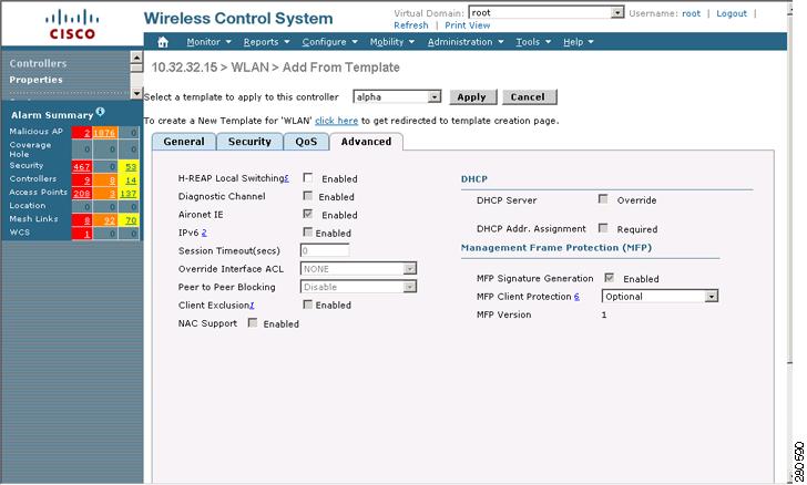
Figure 10-9 WLAN > Add From Template Window
e.
f.
Step 3
a.
b.
c.
d.
e.
Step 4
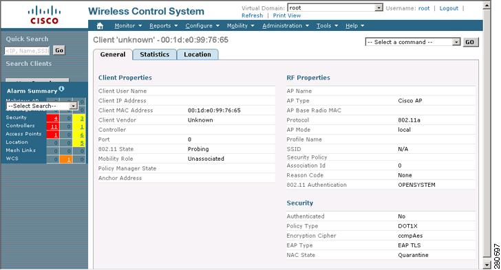
a.
b.
Figure 10-10 Monitor > Client Window
Configuring Wired Guest Access
Wired Guest Access enables guest users to connect to the guest access network from a wired Ethernet connection designated and configured for guest access. Wired guest access ports might be available in a guest office or specific ports in a conference room.
Like wireless guest user accounts, wired guest access ports are added to the network using the Lobby Ambassador feature. Refer to the "Creating Guest User Accounts" section on page 7-11.
Wired Guest Access can be configured in a standalone configuration or in a dual controller configuration employing an anchor and foreign controller. This latter configuration is used to further isolate wired guest access traffic but is not required for deployment of wired guest access.
Wired Guest Access ports initially terminate on a Layer 2 access switch or switch port which is configured with VLAN interfaces for wired guest access traffic.
The wired guest traffic is then trunked from the access switch to a wireless LAN controller. This controller is configured with an interface that is mapped to a wired guest access VLAN on the access switch.
If two controllers are being used, the controller (foreign) that receives the wired guest traffic from the switch then forwards the wired guest traffic to an anchor controller that is also configured for wired guest access. After successful hand off of the wired guest traffic to the anchor controller, a bidirectional Ethernet over IP (EoIP) tunnel is established between the foreign and anchor controllers to handle this traffic.
Note
Note
To create dynamic interfaces for wired guest user access, click Configure > Controllers and after choosing a particular IP address, choose System > Interfaces. Two interfaces should be created: one for Ingress and one for Egress. The Ingress interface provides a path between the wired guest client and the controller by way of a Layer 2 access switch. The Egress interface provides a path out of the controller for the guest client traffic. You must complete the "Creating an Ingress Interface" section and the "Creating an Egress Interface" section before continuing to "Creating a Wired LAN for Guest Access" section. Both the Ingress and Egress Interfaces use the screen as shown in Figure 10-11.
Figure 10-11 Interfaces Summary Window
Creating an Ingress Interface
Follow these steps to create an Ingress interface.
Step 1
Step 2
Step 3
Step 4
Step 5
Step 6
Creating an Egress Interface
Follow these steps to create an Egress interface.
Step 1
Step 2
Step 3
Step 4
Note
Step 5
Step 6
Step 7
Step 8
You are now ready to create a wired LAN for guest access.
Creating a Wired LAN for Guest Access
Follow these steps to configure and enable wired guest user access on the network.
Step 1
Step 2
Figure 10-12 WLAN > Add From Template
Step 3
Note
Step 4
Step 5
Step 6
Step 7
Step 8
Step 9
Note
Step 10
a.
An Email Input check box appears. Check this check box if you want users to be prompted for their e-mail address when attempting to connect to the network.
b.
1.
Internal—Displays the default web login page for the controller. This is the default value.
Customized—Displays custom web login, login failure, and logout pages. When the customized option is selected, three separate drop-down menus for login, login failure, and logout page selection appear. You do not need to define a customized page for all three of the options. Choose None from the appropriate drop-down menu if you do not want to display a customized page for that option.
These optional login, login failure, and logout pages are downloaded to the controller as webauth.tar files. For specifics on downloading custom pages, refer to the "Downloading Customized Web Authentication" section on page 3-17.
External—Redirects users to an external server for authentication. If you choose this option, you must also enter the URL of the external server in the URL field.
You can select specific RADIUS or LDAP servers to provide external authentication on the Security > AAA panel. To do so, continue with Step 11.
Note
Step 11
Step 12
Step 13
Using Switch Port Tracing
Currently, WCS provides rogue access point detection by retrieving information from the controller. The rogue access point table is populated with any detected BSSID addresses from any frames that are not present in the neighbor list. At the end of a specified interval, the contents of the rogue table are sent to the controller in an LWAPP Rogue AP Report message. With this method, WCS would simply gather the information received from the controllers; but with software release 5.1, you can now incorporate switch port tracing of wired rogue access point switch port. This enhancement allows you to react to found wired rogue access points and prevent future attacks. The trace information is available only in the WCS log and only for rogue access points, not rogue clients.
Note
Note
Follow these steps to establish switch port tracing.
Step 1
Step 2
Step 3
Step 4
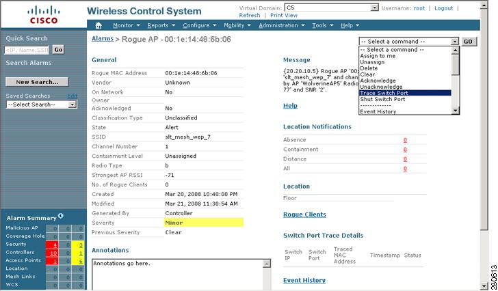
Figure 10-13 Trace Switch Port option on the Alarms > Rogue Page
.
Step 5
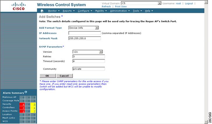
The SNMP communities for the switches are provided in Configure > Switches (see Figure 10-14).
Figure 10-14 Configure > Switches
.
Step 6
If you want to add one switch or use commas to separate multiple switchess, leave the Add Format Type drop-down menu at Device Info.
If you want to add multiple switches by importing a CSV file, choose File from the Add Format Type drop-down menu. The CSV file allows you to generate your own import file and add the devices you want.
Step 7
Step 8
Step 9
Note
Step 10
Step 11
Step 12
Removing Switches
You can remove switches by choosing Configure > Switches and choosing Remove Switches from the Select a command drop-down menu.
Shutting Switch Port
You can suppress the switch port to which the rogue access point is connected. From the Alarms Rogue page (shown in Figure 10-13), choose Shut Switch Port from the Select a command drop-down menu.
The Alarms page will then show the switch IP address, the switch port, the traced MAC address, the port status, and the timestamp of the suppression.