-
Operations and Maintenance Release 4.5
-
Preface
-
Chapter 1 - Cisco BTS 10200 Softswitch Startup and Shutdown Procedures
-
Chapter 2 - Managing Access and Users
-
Chapter 3 - Operations
-
Chapter 4 - Maintaining the BTS 10200 Softswitch
-
Chapter 5 - Maintenance and Diagnostics for External Resources
-
Chapter 6 -- Traffic Measurements
-
Chapter 7 - SNMP Interface
-
Chapter 8 - Congestion Detection and Protection
-
Appendix A - Feature Tones
-
 Feedback
Table Of Contents
Administering and Monitoring System Components
Using Status and Control States
Displaying Operational States of Components with the Status Command
Switching Administrative Service States of Internal Component Pairs with the Control Command
Showing the State of an Application with the Status Application Command
Controlling the State of an Application with the Control Application Command
Determining the Status of a Call Agent with the Status and Control Commands
Determining the Status of and Controlling the Feature Server
Reporting and Controlling the EMS Status with the Status and Control Commands
Determining and Controlling Bulk Data Management System Status with the Status and Control Commands
Additional BDMS Status and Control Examples
Determining System Status with the Status Command
Show and Change Database Usage Commands
Retrieving Batch Data with the Show Command Paging Capability
Example: Controlling the Volume and Format of Data
Example: Ordering and Displaying Specific Data
Viewing and Manipulating Transactions
Showing Entries with the Show Transaction Queue Command
Deleting Entries with the Delete Transaction Queue Command
Using Block and Unblock Commands
Using the Command Scheduler to Schedule Command Executions
Controlling the Subsystem Group In or Out of Service
Requesting the Status of a Subsystem Group
Monitoring the Host Operating System Time
Performing Local Number Portability Functions
Changing lnp-trigger to N (No)
Changing lnp-trigger to Y (Yes)
Changing DN Status to Ported-Out
Deactivating a Customer's Service
Disconnecting Service to a Subscriber with a Ported Telephone Number
Changing a Subscribers Directory Number
Old Directory Number Announcement Removal
Managing Billing Interface and Billing Records
Record Retention Mechanisms in the EMS
Billing Alarm Tracking Mechanisms
Call Detail Block Correlation and Format
Northbound Billing Data Transport
Displaying Active Call Information
Displaying Information on Forwarded Calls
Displaying Information on Three-Way Call and Call Waiting
Assigning Three-Digit Vertical Service Codes (VSC)
Operations
Revised: July 21, 2009, OL-4495-10Introduction
This chapter contains recommended operating procedures for the Cisco BTS 10200 Softswitch. In these procedures, the assumption is that all components have been correctly installed, configured, and provisioned in accordance with the instructions provided in the relevant documentation. All components are assumed to have been successfully started, as described in Chapter 1, "Cisco BTS 10200 Softswitch Startup and Shutdown Procedures".
Note
Operation of the Cisco BTS 10200 Softswitch should be performed by a system administrator who has been trained in the complexities of the system and has some experience administering the system.
Administering and Monitoring System Components
The Cisco BTS 10200 Softswitch provides a user interface for administering and monitoring the following internal system components:
•
•
•
•
Using Status and Control States
This section describes the use of status and control states, and includes the following topics:
•
•
•
•
•
•
•
•
•
Displaying Operational States of Components with the Status Command
The operational (status) states of the components are displayed using the status command. Typical examples of the command are:
status element-manager id=EM01;status element-manager id=BDMS01;status call-agent id=CA146;status feature-server=FSPTC235;status feature-server=FSAIN205;Status states can be in either Normal or Forced mode. Table 3-1 lists status state modes and descriptions.
Switching Administrative Service States of Internal Component Pairs with the Control Command
The operator can use the control commands to switch the administrative service state (target state, or control state) of each internal component pair—EMS pair, BDMS pair, CA pair and FS pair. Each switching command will take approximately 20 seconds to complete on the system.
Following are typical examples of the command:
control call-agent id=CA146; target-state=FORCED-STANDBY-ACTIVE;Invalid parameter value.target_state=FORCED_STANDBY_ACTIVE;Enter one of the following values:
•
•
Control states can be in either Normal or Forced mode. Table 3-2 lists control state modes and descriptions.
.
One of the following messages is returned when a control command is successful:
Reconfigured SuccessfullyAlready in this configurationOne of the following messages is returned when a control command fails:
Mate Changeover TimeoutMate Refused ChangeoverIf this command is executed it will cause a System OutageInvalid ConfigurationLocal Changeover TimeoutLocal Changeover FailureShowing the State of an Application with the Status Application Command
The status application command shows the state of any Cisco BTS 10200 Softswitch application (CA, FS, EMS, BDMS), including uptime, side indications and additional qualifying reason information.
Tip
Command Types
Status
Examples
status application id=CA146;status application id=EM01;Syntax Description
ID
Type of application.
VARCHAR(8): 1-8 ASCII characters. Permitted values are:
CAnnn (or cannn)—CA
EMnn (or emnn)—EMS
BDMSnn (or bdms)—BDMS
FSPTCnnn (or fsptcnnn)—FSPTC
FSAINnnn (or fsainnnn)—FSAIN
Controlling the State of an Application with the Control Application Command
The control application command controls the state of an application instance. This command takes the application specified either in service or out of service.
Tip
Caution
Command Types
Control
Examples
control application id=CA146; action=star;node=prica06control application id=CA146; action=stop;node=prica06control application id=EM01; action=start;node=prica06control application id=EM01; action=stop;node=prica06Syntax Description
Determining the Status of a Call Agent with the Status and Control Commands
This section describes the status and control commands for the Cisco BTS 10200 Softswitch Call Agent.
Status Command
The status command reports the status of a Call Agent.
Command Types
Status
Examples
status call-agent id=CA146;Reply Example:
APPLICATION INSTANCE -> Call Agent [CA146]PRIMARY STATUS -> ACTIVESECONDARY STATUS -> STANDBYReply : Success:Control Command
The control command puts the Call Agent into a specific mode (state).
Command Types
Control
Examples
control call-agent id=CA146; target-state=standby-active;control call-agent id=CA146; target-state=active-standby;Reply Example:
Request was successfulREPLY=CONFIGURATION COMMAND EXECUTED->Reconfigured successfully.Determining the Status of and Controlling the Feature Server
This section describes the status and control commands for the Cisco BTS 10200 Softswitch Feature Server.
Status Command
The status command reports the status of a Feature Server.
Command Types
Status
Examples
status feature-server id=FSAIN205.Cisco.com;Reply Example:
target-state=active-standby;Control Command
The control command puts a Feature Server into a specific mode (state).
Command Types
Control
Examples
control feature-server id=FSAIN205.Cisco.com; target-state=standby-active;Reply Example:
Request was successfulREPLY=CONFIGURATION COMMAND EXECUTED->control feature-server LOCAL STATUSReporting and Controlling the EMS Status with the Status and Control Commands
This section describes the status and control commands for the Cisco BTS 10200 Softswitch Element Management System (EMS). These commands are specific to the EMS. For Billing commands, see the "Determining and Controlling Bulk Data Management System Status with the Status and Control Commands" section.
Status Command
The status command reports the status of an EMS.
Command Types
Status
Examples
status element-manager id=EM01;Reply Example:
Reply : Success:ELEMENT MANAGER STATUS IS... ->APPLICATION INSTANCE -> Element Manager [EM01]PRIMARY STATUS -> ACTIVE_NORMALSECONDARY STATUS -> FAULTYEMS MYSQL STATUS IS ... -> Daemon is running!ORACLE STATUS IS... -> Daemon is running! Control CommandControl Command
The control command puts an EMS into a specific mode (state).
Command Types
Control
Examples
control element-manager id=EM01; target-state=active-standby;Reply Example:
Request was successfulREPLY=CONFIGURATION COMMAND EXECUTED->CONTROL EMS LOCAL STATUSDetermining and Controlling Bulk Data Management System Status with the Status and Control Commands
This section describes the status and control commands for the Cisco BTS 10200 Softswitch Bulk Data Management System (BDMS).
Status Command
The status command reports the status of the BDMS.
Command Types
Status
Examples
status bdms id=BDMS01;Reply Example:
Reply : Success:BILLING SERVER STATUS IS... ->APPLICATION INSTANCE -> Bulk Data Management Server [BDMS01]PRIMARY STATUS -> ACTIVESECONDARY STATUS -> STANDBYBILLING MYSQL STATUS IS... -> Daemon is running!Control Command
The control command puts the BDMS into a specific state (mode).
Command Types
Control
Examples
control bdms id=BDMS01; target-state=active-standby;Reply Example:
Reply : Success:APPLICATION INSTANCE -> Bulk Data Management Server [BDMS01]REASON -> CONFIGURATION COMMAND EXECUTED->CONTROL BDMS LOCAL STATUS SystemAdditional BDMS Status and Control Examples
Use the following steps to verify the status of the BDMS and switch the administrative states.
Step 1
status bdms; id=BDMS01;Reply Example:
BILLING SERVER STATUS IS... ->APPLICATION INSTANCE -> Bulk Data Management Server [BDMS01]PRIMARY STATUS -> ACTIVE_NORMALSECONDARY STATUS -> FAULTYBILLING ORACLE STATUS IS... -> Daemon is running!Reply : Success:Step 2
control bdms id=BDMS01; target-state=FORCED_ACTIVE_STANDBYReply Example:
Success:APPLICATION INSTANCE -> Bulk Data Management Server [BDMS01]REASON -> Application instance reconfigured successfullyStep 3
status bdms; id=BDMS01;Reply Example:
Success:REPLY=CONFIGURATION COMMAND EXECUTED -> status billing_serverPRIMARY STATUS -> ACTIVE_FORCEDSECONDARY STATUS -> STANDBY_FORCEDStep 4
control bdms id=BDMS01; target-state=FORCED_STANDBY_ACTIVEReply Example:
Request was successful.REPLY=CONFIGURATION COMMAND EXECUTED -> Reconfigured SuccessfullyStep 5
status bdms id=BDMS01;Reply Example:
Request was successful.REPLY=CONFIGURATION COMMAND EXECUTED -> status billing_serverPRIMARY STATUS -> STANDBY_FORCEDSECONDARY STATUS -> ACTIVE_FORCEDStep 6
control bdms id=BDMS01; target-state=FORCED-ACTIVE-STANDBY;Reply Example:
Request was successful.REPLY=CONFIGURATION COMMAND EXECUTED -> Reconfigured SuccessfullyDetermining System Status with the Status Command
The status system command returns the status of all applicable components of the system.
Command Types
Status
Examples
status system;Reply Example:
Checking Call Agent status ...Checking Feature Server status ......Checking Billing Server status ...Checking Billing Oracle status ...Checking Element Manager status ...Checking EMS MySQL status ...Checking ORACLE status ...CALL AGENT STATUS IS... ->APPLICATION INSTANCE -> Call Agent [CA146]PRIMARY STATUS -> ACTIVESECONDARY STATUS -> STANDBYFEATURE SERVER STATUS IS... ->APPLICATION INSTANCE -> Feature Server [FSPTC235]PRIMARY STATUS -> ACTIVESECONDARY STATUS -> STANDBYFEATURE SERVER STATUS IS... ->APPLICATION INSTANCE -> Feature Server [FSAIN205]PRIMARY STATUS -> ACTIVESECONDARY STATUS -> STANDBYBILLING SERVER STATUS IS... ->APPLICATION INSTANCE -> Bulk Data Management Server [BDMS01]PRIMARY STATUS -> ACTIVESECONDARY STATUS -> STANDBYBILLING ORACLE STATUS IS... -> Daemon is running!ELEMENT MANAGER STATUS IS... ->APPLICATION INSTANCE -> Element Manager [EM01]PRIMARY STATUS -> ACTIVESECONDARY STATUS -> STANDBYEMS MYSQL STATUS IS ... -> Daemon is running!ORACLE STATUS IS... -> Daemon is running!Reply : Success:
Activating a Media Gateway
The control command is used to change the state of the media gateway to "in service." You should monitor the Cisco BTS 10200 Softswitch transaction queue to verify that the media gateway has been successfully added before trying to activate the media gateway.
To verify that the media gateway has been added and to activate the media gateway, complete the following steps:
Step 1
show transaction-queue transaction-id=1029944382523Reply: Success: Database is void of entries.Step 2
control mgw id=<mgw-id>; target-state=ins; mode=forced;Data elements specified in this command are:
•
•
•
Archiving Your Database
Step 1
Step 2
su - oracleStep 3
dbadm -r dbadm -r get_unpushed_trans
You should see the following:
==============================================
Transaction statements (calls) not been pushed
==============================================no rows selectedIf the output shows unpushed transactions, wait a few seconds and repeat this step until the queue is empty.
Step 4
exitStep 5
Step 6
ls -l /var/ypIf the result is "no such file or directory", enter:
mkdir -p /var/ypStep 7
mount <nfsserver hostname/ip>:/<share directory> /mntExample:
mount 10.89.183.253:/opt/archive /mntStep 8
tar -cvf /mnt/<local_hostname>.tar host*Example:
<hostname>#tar -cvf bts-prica.tar host.*Step 9
mv /bin/date /bin/date.origmv /bin/.date /bin/dateStep 10
<hostname>#flarcreate -n <archive name> -x /opt -S -c /mnt/<file name>
Note
Step 11
tar -cvf - /opt/* |gzip -c >/opt/<hostname_release>.tar.gzStep 12
mv /bin/date /bin/.datemv /bin/date.orig /bin/dateStep 13
umount /mnt
Show and Change Database Usage Commands
This section describes the following:
•
•
•
Retrieving Batch Data with the Show Command Paging Capability
The show command paging capability is used for retrieving subscriber related records (such as SUBSCRIBERS, TERMINATIONS, SUBSCRIBER_SERVICE_PROFILES) in batches.
The following parameters apply to all show commands that operate on provisioning data. These parameters are particularly useful when displaying tables containing large amounts of data such as SUBSCRIBERS and TERMINATIONS.
•
•
Note
•
•
Example: Controlling the Volume and Format of Data
In the following example, the show command parameters are used to control the volume and format of data to be displayed:
show subscriber limit=1000; start_row=<next page value>;Where:
•
•
Example: Ordering and Displaying Specific Data
In the following example, the show command parameters are used to order and display only the desired data:
show subscriber limit=1000; start_row=<next page value>; display=id,sub_service_profile; order=id;Where:
•
•
•
•
Show Database Usage Command
The show db-usage command returns and modifies the maximum number of records allowed, as well as the number of licensed and current database records. Records can be shown and changed but cannot be deleted.
The EMS updates the current number of records field in real time. The db-usage command also uses the Database Threshold (db-thresholds) table, which contains default alarm threshold parameters that are provisioned during installation. Parameters can be changed and shown. The default threshold parameters are:
•
•
•
Note
Use the following command example to show db-usage statistics:
show db-usage table-name=dial_plan;Change db-usage
Use the following command example to change db-usage tokens and values:
change db-usage table-name=dial-plan; minor-threshold=70;major-threshold=80;
critical-threshold=95;
Viewing and Manipulating Transactions
This section describes the commands and tables for viewing and manipulating transactions.
Transaction Queue Command
The transaction-queue command allows users to view and delete entries in a transaction queue, if any exist.
The Transaction Queue table tracks updates into the database, as well as into the shared memory of the Call Agent and Feature Servers. Entries should never remain in the transaction queue for more than a few seconds, unless an Element Management System (EMS), Call Agent, or Feature Server is in an error state. In case of an error state, the transaction queue continues to store entries for later updates.
Note
Showing Entries with the Show Transaction Queue Command
Use the following command example to show any entries in a transaction queue:
show transaction-queue target=CA146Deleting Entries with the Delete Transaction Queue Command
Use the following command example to delete any entries in a transaction queue.
delete transaction-queue target=CA146
Caution
Blocking Provisioning
Prevent BTS provisioning during an upgrade or maintenance windowfrom the following interfaces:
•
•
•
•
Note
If you block provisioning before performing an SMG restart or EMS reboot, blocking is still enforced when these applications return to in-service state.
There are two levels of blocking:
•
•
Who Can Block?
Only terminal type "MNT" users can use these blocking and unblocking commands. "MNT" users are never blocked. "MNT" users issue these commands from either Active or Standby EMS.
Who Can Be Blocked?
A blocking command applies to all non-"MNT" users on terminals on either Active or Standby EMS. Commands do not execute for:
•
•
Commands are not queued for execution after unblock. The CLI user prompt changes when blocked, notifiying the user their commands will not execute.
Using Block and Unblock Commands
Step 1
•
•
Step 2
Step 3
Viewing a Call Trace Summary
The Call Trace Summary command reports the information gathered when a customer activates a trace by pressing *57 on the telephone. This command logs information pertaining only to the most recently received call. Report is the only command type. Using the command without any tokens returns all entries in the table.
Use the following command example to report call trace information:
report call-trace-summary
Note
The report appears on the screen. No HTML report is generated.
Using the Command Scheduler to Schedule Command Executions
The Command Scheduler allows you to schedule a command to execute daily, weekly, or monthly at a specific time. Once a command is scheduled, the Scheduler allows you to remove a command from the schedule. Regardless of whether the command previously executed, the command can be removed at any time. If the command is scheduled to recur and is currently executing within the Element Management System (EMS), the command completes in a normal fashion but is removed from the list from that point forward.
It is often necessary to schedule commands to occur during periods of least system activity. Using the start-time and recurrence command tokens, you can schedule commands at any time and at any frequency. The recurrence token schedules a command daily, weekly, or monthly. Scheduling a command without the recurrence token causes the Command Scheduler to execute the command only once.
The characteristics of a scheduled command are read once at execution time. During execution, the characteristics can be changed but do not affect the command that is running.
Showing a Scheduled Command
Use the following command example to show a particular scheduled command:
Note
show scheduled-command id=1234;Adding a Scheduled Command
Use the following command example to add a scheduled command:
add scheduled-command start-time=2001-10-01 12:22:22; noun=database; verb=audit;Changing a Scheduled Command
Use the following command example to change a scheduled command:
change scheduled-command id=1234; start-time=2001-10-02 20:00:00;Deleting a Scheduled Command
Use the following command example to delete a scheduled command:
delete scheduled-command id=1234;Controlling the Subsystem Group In or Out of Service
The Subsystem Group table has a status associated with it. The operator can control a subsystem group in or out of service. Controlling the subsystem group out of service has the same affect as controlling all the subsystems in the subsystem group out of service. Controlling the subsystem group in service puts all subsystems in the group in service.
The following CLI command controls both subsystem/OPC combinations out of service:
control subsystem_grp id=CNAM; mode=forced; target_state=UOS;SUBSYSTEM GRP ID -> CNAMINITIAL STATE -> User in serviceRESULT STATE -> User out of serviceREQUEST STATE -> User out of serviceFAIL REASON -> ADM found no failureREASON -> ADM executed successfullyRESULT -> ADM configure result in successReply : Success: CLI change successfully
Note
Requesting the Status of a Subsystem Group
The operator may request the status of the subsystem group table. The following example CLI command requests status:
status subsystem_grp id=CNAMSUBSYSTEM GRP ID -> CNAMREASON -> ADM executed successfullyRESULT -> ADM configure result in successADMIN STATE -> User in serviceOPER STATE -> Subsystem Group allowedReply : Success:Monitoring the Host Operating System Time
The Solaris Operating System (OS) obtains the system time automatically through network time protocol (NTP) services.
Caution
Performing Local Number Portability Functions
This section describes local number portability (LNP) operation on the Cisco BTS 10200 Softswitch in the following subsections:
•
To perform LNP functions, start with establishing a CLI session. See Logging into the EMS Using CLI, page 2-2 for information.
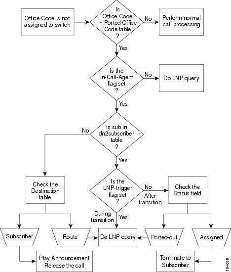
LNP Call Flow
Figure 3-1 shows the processing of a call in which the office code is not one that is normally assigned to the switch. This chart points out the various parameters and flags that must be set to ensure that calls are processed correctly before, during, and after a subscriber's number is ported-in or ported-out of a switch.
Figure 3-1 Ported-in Call Processing for Originating Calls
The porting-in process is complete when:
•
•
•
•
•
Porting-out a Subscriber
In some cases, subscribers will want to discontinue their service, but take their telephone number with them to their new service provider. This is similar to the port-in case described previously, where the lnp-trigger is set to Y at the beginning of the porting process to ensure that all calls are routed according to the national LNP databases. This is necessary because the national LNP database has authority on when and where to route calls to a ported number, although the number may still exist in the local DN2SUBSCRIBER table.
When subscribers want to move their service to another service provider and request LNP service, log in to the Cisco BTS 10200 Softswitch as described in the "Logging into the EMS Using CLI" section on page 2-2, and enter the CLI commands as described in the following sections:
•
•
•
Activating a Subscriber
Use the control command to change the state of the subscriber to "in service." Monitor the Cisco BTS 10200 Softswitch transaction queue to verify that the subscriber has been successfully added before trying to activate the subscriber.
To verify that the subscriber has been added and to activate the subscriber, complete the following steps:
Step 1
show transaction-queue transaction-id=1029944382524Text similar to the following is displayed:
Success: Database is void of entries.Step 2
control subscriber-termination id=<subscriber id>; target-state=INS; mode=FORCED;The data elements specified in this command are described as follows:
Changing lnp-trigger to N (No)
After the activation for a ported-in number is complete, the Cisco BTS 10200 Softswitch must be updated so that calls to this number from MTAs on this switch are routed directly to the subscriber's MTA, instead of having the switch perform an LNP query and route the call to the CLEC switch, only to have it route the call back to the Cisco BTS 10200. To accomplish this, reset the lnp-trigger flag to N.
To reset the lnp-trigger flag to N, complete the following steps:
Step 1
show office-code digit-string=<NPA-NXX of the ported TN>;The Cisco BTS 10200 Softswitch returns the office-code-index.
Step 2
change dn2subscriber office-code-index=
	<office-code-index of ported TN's NPA-NXX>;
dn=<XXXX of the ported TN>; lnp-trigger=N;
Note
Changing lnp-trigger to Y (Yes)
When a service order to port out a number has been issued, change the lnp-trigger to Y (Yes) to ensure the routing of calls to the number is done according to the NPAC SMS national LNP databases.
To change the lnp-trigger to Y (Yes), perform the following steps:
Step 1
show office-code digit-string=<NPA-NXX of the ported TN>;The Cisco BTS 10200 returns the office-code-index.
Step 2
change dn2subscriber office-code-index=
	<office-code-index of ported TN's NPA-NXX>;
dn=<XXXX of the ported TN>; lnp-trigger=y;
Changing the lnp-trigger to Y (Yes) results in calls to this DN initiating an unconditional LNP query.
Leave the status of the DN=ASSIGNED in the DN2SUBSCRIBER table because initially, calls to the DN may have to be routed to the porting-out subscriber's MTA, based on the results of the LNP queries. Wait until the CLEC reports a Completed state for the transfer before changing the status of the DN.
Changing DN Status to Ported-Out
After the CLEC reports a Completed state, change the status of the number in the DN2SUBSCRIBER table to "ported-out" by completing the following steps:
Step 1
show office-code digit-string=<NPA-NXX of the porting TN>;The Cisco BTS 10200 Softswitch returns the office-code-index.
Step 2
change dn2subscriber office-code-index=
	<office-code-index of porting TN's NPA-NXX>;
dn=<XXXX of the porting TN>; status=ported-out; sub-id=null;
Deactivating a Customer's Service
To deactivate a customer's service, complete the following steps:
Step 1
control subscriber-termination target-state=oos; mode=forced; id=<subscriber id>;Data elements specified in this command are:
•
•
•
Step 2
control mgw id=<mgw-id>; target-state=oos; mode=forced;The data elements specified in this command are:
•
•
•
Step 3
delete subscriber-service-profile sub-id=<subscriber id>; service-id=1;Data elements specified in this command are:
•
•
Step 4
delete subscriber id=<subscriber-id>;The only data element specified in this command is:
•
Step 5
delete termination prefix=aaln/; port-start=1; port-end=2; mgw_id=<mgw-id>;Data elements specified by this command are:
•
•
•
•
Step 6
delete mgw id=<mgw-id>;The only data element specified by this command is:
•
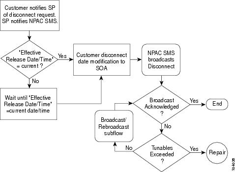
Disconnecting Service to a Subscriber with a Ported Telephone Number
Disconnecting service to a subscriber who has a ported telephone number requires interaction with the NPAC SMS, as illustrated in Figure 3-2.
To disconnect a subscriber who has a ported telephone number, complete the following steps:
Step 1
Step 2
a.
b.
Note
Step 3
NPAC SMS logs the update in a history file, and calls to the telephone number are routed as if it were a non-ported number.
Figure 3-2 Disconnect Ported Number Work Flow
Changing Subscriber DN
The change number feature enables you to change the directory number of a subscriber. The following procedures enable you to change a directory number of a subscriber and to remove the old directory number announcement.
Changing a Subscribers Directory Number
To change the directory number of a subscriber, do the following:
Step 1
change sub id=<id>; dn1=<new-DN>;Example:
change sub id=sub1; dn1=206-222-1841;Step 2
show sub id=<id>Example:
show sub id=sub1;Dn1 indicates 206-222-1841Step 3
show changed-number old-dn=<old-dn>Example:
show changed-number OLD-DN=206-222-2345Step 4
show dn2subscriber FDN=<old-DN>;Example:
show dn2subscriber FDN=206-222-2345;Check if the status of the new DN is assigned.
show dn2subscriber FDN=<new-DN>;Example:
show dn2subscriber FDN=206-222-1841;Step 5
Step 6
If an announcement is not played, do the following:
•
show release-cause id=22;•
show annc id=118;
Old Directory Number Announcement Removal
If you do not want to play an announcement for the old DN anymore, do the following:
Step 1
delete changed-number old-DN=<old-DN>;Step 2
change dn2subscriber DN=<old-DN>; status=DISC;
Troubleshooting LNP Problems
See the Cisco BTS 10200 Troubleshooting Guide for details on troubleshooting LNP problems.
Problems can arise when porting a subscriber's telephone number from one service provider to another. The Network Interconnection Interoperability Forum (NIIF), a part of the ATIS organization, has published a document (ATIS/NIIF-0017) that includes detailed steps that service providers should follow when LNP problems are encountered. The document is titled Guidelines for Reporting Local Number Portability Troubles in a Multiple Service Provider Environment, and it is available at http://www.atis.org/atis/clc/NIIF/niifdocs.htm.
The NIIF also maintains the National LNP Contact Directory, a protected document that provides telephone numbers of 24x7 LNP-qualified contacts for each service provider. The directory is located at the URL given above. You can download and submit an application for a password at the same URL.
Managing Billing Interface and Billing Records
See the Cisco BTS 10200 Softswitch Billing Interface Guide for details on managing the billing interface and billing records.
The billing subsystem on the EMS gathers all billing related call events from call processing, formats them into a standard format, and transmits them to an external collection device. The interface to the billing mediation device can vary from carrier to carrier, thus this subsystem supports a flexible profiling system.
The billing subsystem includes the following functions:
•
•
•
•
•
•
Record Retention Mechanisms in the EMS
A "worst case number of records required" is determined, based on predicted call capacities and call type mixtures. Once this number of records has been reached, the next entry rolls over to the first record in the database and starts overwriting from this record onwards.
The following sample calculation is used to predict the number of records needed to store 48 hours of records:
100 calls/second in busy hour yields an average daily mean of 45 calls/second X 60 seconds/ minute X 60 minutes/hour X 48 hours = 7,776,600 records.
Billing Alarm Tracking Mechanisms
The billing manager process in the EMS tracks the total number of records the billing database can store, the number of unacknowledged records, and the current percentage of the database that is occupied by unacknowledged records. This information is then compared against the threshold levels set in the billing alarm database. If the current amount of billing data exceeds thresholds in the database, then the billing manager issues alarms. The billing manager resets the alarms as the storage levels drop below the thresholds.
Call Detail Block Correlation and Format
CDBs are produced from the current information sent from the billing generator in the CA to the billing manager in the EMS. An indication that the call has completed all signaling activities can be detected and used as a marker that all billing for the given call is now complete. Each of the billing event messages (BEM) that are portions of a call in progress, are stored in a staging area in the billing generator, waiting for call completion. Once the complete call content is present, the CDB is constructed from the individual BEMs and sent to the billing manager in the EMS.
Northbound Billing Data Transport
Billing data is transported to the customer's OSS network via FTP of batch files containing the Call Detail Blocks.
Note
Displaying Active Call Information
Active Call Information Display displays the call information of a currently active call.
Query Command
The operator uses a CLI command (query call-trace) and enters the subscriber phone number or other suitable input to retrieve information about a subscriber call in progress based on an input parameter, then views the call information from the output. It applies either to originating or terminating calls.
•
•
–
–
–
–
–
–
–
The list of input parameters and the list of displayed output fields are both documented in the "Query" section of the Cisco BTS 10200 Softswitch Command Line Reference Guide.
Error Message
A query is rejected with an error message in the following cases:
•
•
•
Displaying Information on Forwarded Calls
Forwarded calls are handled as shown in the following scenario:
•
•
•
•
Note
Displaying Information on Three-Way Call and Call Waiting
If a caller is involved in more than one call at the same time, such as a three-way call or a call-waiting scenario, the output gives the details of both calls.
Display of Query Results
Following are examples of displays from call-trace queries for a POTS subscriber (brief mode selected):
CALL-STATE=CONNECTED (CLG):POTS-SUB 469-555-1234 (CLD):POTS-SUB 469-255-4567
CALL-STATE=CALL-SETUP (CLG):POTS-SUB 469-555-1234 (CLD):SIP-SUB 469-255-4568
CALL-STATE=ALERTING (CLG):POTS-SUB 469-555-1234 (CLD):H323-SUB 469-255-4569
CALL-STATE=CONNECTED (CLG):POTS-SUB 469-555-1234 (CLD):POTS-MLHG MLHG-ID=mlhg1 TERMINAL=23
CALL-STATE=CALL_SETUP (CLG):POTS-SUB 469-555-1234 (CLD):POTS-CTXG CTXG-ID=ctxg1 EXT=1234
CALL-STATE=ALERTING (CLG):POTS-SUB 469-555-1234 (CLD):SS7 TGN-ID=123 TRUNK-ID=456
CALL-STATE=CONNECTED (CLG):POTS-SUB 469-555-1234 (CLD):ISDN TGN-ID=123 TRUNK-ID=456
CALL-STATE=CALL-SETUP (CLG):POTS-SUB 469-555-1234 (CLD):CAS TGN-ID=123 TRUNK-ID=456
CALL-STATE=ALERTING (CLG):POTS-SUB 469-555-1234 (CLD):SIP_TG SIP-CALL-ID=<sip-call-id>
CALL-STATE=CONNECTED (CLG):POTS-SUB 469-555-1234 (CLD):H323-TG H323-CALL-ID=<h323-call-id>
Assigning Three-Digit Vertical Service Codes (VSC)
To assign three-digit VSCs:
Step 1
Note
Step 2
Step 3
Changing NTP or DNS Server
To change either the NTP or DNS server:
Step 1
Step 2
Step 3
Step 4
Step 5
Step 6
Step 7